Dynamic solid surface tension causes droplet pinning and depinning
Abstract
The contact line of a liquid drop on a solid exerts a nanometrically sharp surface traction. This provides an unprecedented tool to study highly localised and dynamic surface deformations of soft polymer networks. One of the outstanding problems in this context is the stick-slip instability, observed above a critical velocity, during which the contact line periodically depins from its own wetting ridge. Time-resolved measurements of the solid deformation are challenging, and the mechanism of dynamical depinning has remained elusive. Here we present direct visualisations of the dynamic wetting ridge formed by water spreading on a PDMS gel. Unexpectedly, it is found that the opening angle of the wetting ridge increases with speed, which cannot be attributed to bulk rheology, but points to a dynamical increase of the solid’s surface tensions. From this we derive the criterion for depinning that is confirmed experimentally. Our findings reveal a deep connection between stick-slip processes and newly identified dynamical surface effects.
Liquid drops on vertical glass windows frequently get stuck due to sub-micrometric heterogeneities of the surface. Indeed, while a drop on a perfectly flat homogeneous surface will slide down under its own weight, surface defects result into pinning of the contact line and can give rise to a characteristic stick-slip motion. Different aspects of the depinning transition on rigid surfaces have been studied experimentally and theoretically Bonn et al. (2009), revealing critical phenomena Rosso and Krauth (2002) that are blurred by thermal activation at the nanoscale Perrin et al. (2016). From an engineering perspective, there is a continued effort in designing surfaces with low contact angle hysteresis for purposes of hydrophobicity, self-cleaning, or anti-fouling coatings Solomon et al. (2016); Quéré (2008).
Recently, wetting of soft surfaces has generated a large interest: The liquid-like surface properties of reticulated polymer networks and brushes can offer nearly hysteresis-free substrates Lhermerout et al. (2016); Snoeijer et al. (2018). However, despite the absence of hysteresis, drops on these soft surfaces do exhibit a stick-slip motion when forced to spread beyond a threshold velocity Kajiya et al. (2013); Kajiya (2014); Park et al. (2017); Karpitschka et al. (2015). This stick-slip behaviour is highly unexpected, since the steadily moving contact line is not pinned to a material point of the solid, but “surfs” a wetting ridge created by the capillary forces located at the contact line. This suggests a rather intriguing scenario of self-pinning, and subsequent depinning of the contact line from its own wetting ridge. While stick-slip motion was qualitatively correlated to the viscoelastic rheology of the substrate Kajiya et al. (2013); Kajiya (2014), or weakening of the wetting ridge Park et al. (2017), the current models predict a stable steady-state motion even at large velocities Karpitschka et al. (2015). As such, there is no explanation why the contact line would depin from its own ridge and start a stick-slip cycle.
In this Letter we identify the origin of the stick-slip transition using a direct high-speed visualisation of the full wetting ridge during self-pinning and depinning. The experiments reveal an increase of the solid angle at the ridge tip with contact line velocity, which is interpreted as a dynamical increase of solid surface tensions. We identify the criterion for the instability and as such reveal the origin of the stick-slip motion: the increased solid angle enables the contact line to depin from its ridge and rapidly slide down its own wetting ridge.
Wetting ridge visualisation –
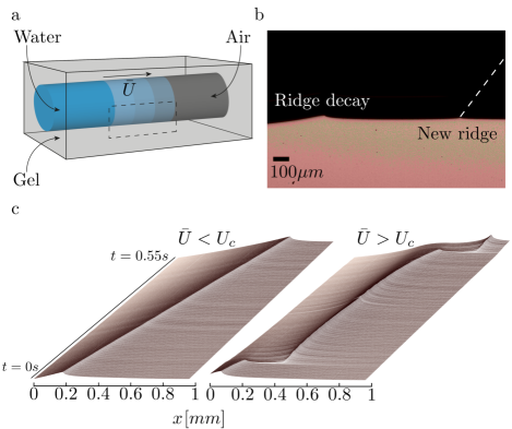
It is notoriously difficult to image the wetting ridge below the contact line. Techniques such as confocal Xu et al. (2017) or X-ray microscopy Park et al. (2014, 2017) have provided excellent spatial resolution, but the rapid dynamics during stick-slip motion constitute a challenge. To overcome this, we present the setup shown in Fig. 1(a) consisting of a square block of transparent gel with a cylindrical cavity. The block has a width of 10 mm, the cavity diameter is 4 mm, leaving about 3 mm of gel thickness. These dimensions ensure a separation of length-scales where the elastocapillary length is small compared to the thickness and the meniscus, while the effect of gravity is still negligible. The cavity is partially filled with MilliQ water. The contact line pulls the gel inwards, creating an axisymmetric wetting ridge. This setup allows to accurately trace the edge of the gel when observing from the side [dashed rectangle in Fig. 1(a)] without the otherwise unavoidable optical distortions. Using a high speed camera (3200 frames per second) and a long working distance microscope (giving a spatial resolution of m/pixel) we image the wetting ridge, and the stick-slip motion with the necessary spatio-temporal resolution. A sample image is shown in Fig. 1(b), which was taken during a rapid “slip” event after the contact line depinned from the ridge. The image reveals both the new wetting ridge (right) and the decaying old wetting ridge (left).
The reticulated polymer used is a PDMS gel (Dow Corning CY52-276, mixed at a 1.3:1 (A:B) ratio). The dynamic modulus is accurately described by , where the static shear modulus Pa, s and the exponent (cf. Supplementary Information sup .) With the surface tension of MilliQ water mN/m, this gives rise to the elastocapillary length mm, which makes the wetting ridge easily accessible for optical microscopy. We verified that the experimental aspects such as the surface tension of the water and the wetting ridge dynamics remain consistent over extended periods of time (days), even when leaving the water in contact with the PDMS. The motion of the contact line is imposed by filling the cavity at a constant volumetric rate using a syringe pump; control parameter is the imposed averaged contact line speed . The opening angle of the solid ridge was measured at the micron scale within by fitting the gel profile on both sides of the ridge (cf. Supplementary Information sup ). The contact angle of the liquid was measured in a separate experiment using a sessile drop on a flat surface of the same gel of sufficiently large thickness.
From steady motion to stick-slip cycles –
At small velocity , the contact line moves in a steady state, as can be seen by the left space-time diagram in Fig. 1(c). This steady regime has been studied in previous works Karpitschka et al. (2015); Shanahan and Carre (1995); Carré et al. (1996); Long et al. (1996); Karpitschka et al. (2016); Zhao et al. (2018), which have shown that the motion is governed primarily by the viscoelastic dissipation inside the solid. The speed at which a drop can spread thus depends on the rheology of the solid, as well as on the size of the wetting ridge where most of the dissipation occurs.
Our prime interest lies in the high velocity regime, where wetting is forced beyond a critical speed . The contact line motion then turns unstable, and results into a stick-slip behaviour that we resolve in detail at the scale of the wetting ridge. The space-time plot of a stick-slip cycle is shown in Fig. 1(c), with the corresponding dynamic wetting ridges presented in detail in Fig. 2.
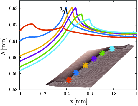
At the start of a cycle, the contact line depins from the wetting ridge and suddenly moves with a much higher velocity over the substrate (slip phase). The first data in Fig. 2 (red) shows the profile just after depinning, where we observe both the abandoned wetting ridge (rounded tip, left) and the newly formed wetting ridge (sharp tip, right). The old ridge is no longer pulled by the contact line and will decay over time. The evolution of the new ridge can be followed by the subsequent profiles in Fig. 2 (from dark blue to light blue). The wetting ridge initially grows, while also moving along the surface. In contrast to the sudden depinning, the transition to the stick phase is characterized by a continuous deceleration of the ridge. The growing ridge causes more viscoelastic dissipation, slowing down its motion. At a later stage, the wetting ridge becomes markedly asymmetric, with a large rotation of the ridge tip (light blue). Finally, the contact line depins and the stick-slip cycle is repeated.
The speed during the slip phase is two to three orders of magnitude faster than during the stick phase (Fig. 1c). Slip velocities, between and mm/s, are actually comparable to those measured during the wetting of a rigid surface Bonn et al. (2009); Snoeijer and Andreotti (2013). In this phase of rapid motion there is essentially no wetting ridge, and hence negligible viscoelastic dissipation inside the solid. During the slow phase, the velocity typically remains larger than of the critical speed mm/s. Therefore, the contact line never really “sticks” to a material point of the substrate, but rather creeps, as for the stick-slip associated with solid friction Baumberger and Caroli (2006).
The depinning from the wetting ridge cannot be explained as a simple consequence of the viscoelastic “friction” force. Namely, classical stick-slip in solid friction is due to the sharp decrease of the friction force with velocity, modeled in Coulomb’s law by a jump from static to dynamic friction. The decrease of friction causes an overshoot of the speed of the slipping object, which in turn induces the irregular stick-slip regime. However, the gel used in these experiments presents a loss modulus increasing monotonically with frequency, with exponent , so that the dissipation in each material element, and subsequently the effective friction force, increases with velocity. Indeed, theory based on linear viscoelasticity assuming constant surface tensions, predicts a stable, steady solution for all velocities Karpitschka et al. (2015). This calls for a more detailed investigation, given below, of how the contact line detaches from the wetting ridge.
Dynamic surface tension –
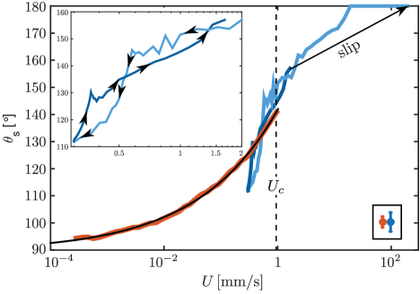
The main surprise of the profiles in Fig. 2 is that the solid angle at the tip of the wetting ridge is not constant, but increases with velocity; it will provide the key to the depinning mechanism. Figure 3 shows the dynamics of for both the regime of constant velocity () and during the stick-slip cycle (). In the steady-state regime (red) we observe a gradual increase with velocity, from the static value at equilibrium to at the critical speed . The data is very accurately described by the fit (black). A similar trend is observed during the stick-slip cycle (blue), where denotes the instantaneous contact line velocity. The moment of slip is indicated by the arrow, where the surface is very flat and we set to . Then, as the contact line velocity decreases, a decrease in is observed that follows the same trend as in the steady-state, in first approximation. At the minimum velocity, slightly undershoots the steady-state curve in red. Subsequently the contact line velocity increases, while follows the steady state curve until depinning occurs and the cycle is repeated.
This unexpected increase of with velocity can be interpreted as a dynamical increase of the solid surface tensions. Here we follow Xu et al. (2017, 2018), where is used to measure surface tensions based on the Neumann condition for the contact angles. This is a balance of forces applied to an elementary material system surrounding the contact line: the liquid surface tension is counteracted by the solid surface tensions, respectively (solid-vapor) and (solid-liquid). By this argument, we assume that the bulk viscoelastic stress cannot contribute on small scales, which is in fact consistent with the shear-thinning nature () of the gel. This point can be quantified by estimating the bulk stress at a distance from the contact line. The characteristic frequency at which the material is excited by the moving contact line is , which for the present rheology implies a bulk stress . When computing the integral of viscoelastic stress from a distance up to the contact line, we find ; for shear-thinning materials with , this integrated stress vanishes in the limit , so ultimately capillary effects prevail. The cross-over scale from bulk-to-surface is obtained from the balance , which gives . For the gel used in our experiment, this gives for mm/s, ensuring that the measurement of is indeed not obscured by bulk effects. Importantly the corresponding characteristic frequencies are within the range that is accessible by bulk rheometry (see supplement sup ).
Depinning mechanism –
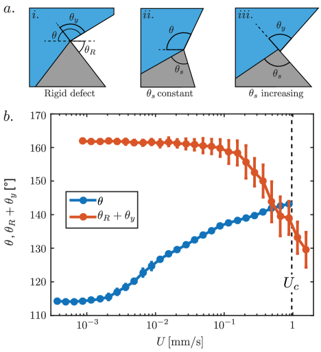
Finally, we demonstrate how the change in is indeed responsible for depinning [Fig. 4(a)]. First we revisit the classical depinning from a “rigid wedge” Gibbs (1961); Oliver et al. (1977), used as a model for topographic roughness on stiff solids [panel (i)]. The contact line can slide off the ridge once the liquid angle with respect to the inclined edge exceeds the Young’s angle that marks the wetting equilibrium. Any (virtual) displacement to the right with a lower angle will result in a restoring force that pushes the contact line back to the tip of the ridge. The depinning criterion thus reads
| (1) |
where is the liquid angle with respect to the horizontal, while is inclination angle on the right of the wedge [panel (i)]. A similar argument applies for depinning to the left, which in the case of a rigid wedge gives rise a range of possible values for . This is the source of contact angle hysteresis on rigid topography, for which (1) goes by the name of the Gibbs inequality Dyson (1988). For soft wetting ridges, however, the mechanics is fundamentally different – for example, no contact angle hysteresis is observed Snoeijer et al. (2018). Instead, any change of the liquid angle is followed by a rotation of the ridge itself, as is clearly visible in Fig. 2. In the absence of changes of surface tensions, there is no depinning, but instead foresees a stable steady motion at all speeds Karpitschka et al. (2015). In this case of constant surface tensions, the solid angle takes on a constant value (dictated by the Neumann balance), and and will always rotate by exactly the same amount to maintain a constant [panel (ii)]. By consequence the depinning criterion (1) will never be satisfied. All this changes dramatically, however, when surface tensions allow for an increase of , and thereby reduce , enabling the contact line to slide off the wetting ridge [panel (iii)].
This scenario for dynamics-induced depinning is confirmed in Fig. 4(b), where we verify the depinning criterion (1). The blue data shows the increase of the liquid angle with velocity . This is compared to the angle relative to the right-side of the ridge, , shown as the red data. In accordance with recent work Xu et al. (2017); Schulman et al. (2018); Snoeijer et al. (2018), we set to a constant value measured from equilibrium. The motion leads to a decrease of that allows for a crossing of the curves that indeed coincides with [Fig. 4(b)]. This is direct evidence for the depinning criterion (1) as the cause of stick-slip. This mechanism does not involve any sudden failure of the Neumann condition, as was suggested in Park et al. (2017), which is corroborated by the gradual evolution of .
Discussion and outlook –
In summary, we revealed that the surface tension of a soft solid is a truly dynamical quantity, which has important consequences in contact mechanics. It provides the mechanism responsible for depinning and the rapid stick-slip motion of drops on soft substrates. The change in ridge angle provides direct evidence for a dynamic coupling between the surface tensions and the mechanical state of the substrate. A similar variability of , and thus of the solid’s surface tensions, was recently observed for static drops, when progressively stretching the substrate Xu et al. (2017, 2018). This was attributed to the so-called Shuttleworth effect Shuttleworth (1950); Andreotti and Snoeijer (2016); Style et al. (2017), where the surface tension depends on the elastic surface strain. It is tempting to interpret the results of Fig. 3 along the same lines, by considering the strain induced by the droplet motion. Indeed, the motion of the contact line induces a rotation (visible in Fig. 2) of the wetting ridge with respect to its more symmetric static shape; this rotation leads to an increase of the stretch on the liquid side and a decrease of the stretch on the vapour side. However, the observed change of is found to change as , while the rotation angle – and its induced strain – exhibits a much weaker dependence dictated by the rheology exponent Karpitschka et al. (2015). It is thus unlikely that the strain-dependence of surface tension is sufficient to explain our observations in Fig. 3.
The above considerations suggest that surface tension of such a polymer gel is a truly dynamic quantity that depends on the rate of strain at the surface as the contact line passes by. This opens the exciting perspective of surface rheological effects, as is for example known for interfaces with surfactants Fuller and Vermant (2012); Ritacco et al. (2011). For the present case of cross-linked polymer networks, this will require a detailed understanding of non-equilibrium interfacial effects that find their origin at a scale smaller than the distance between cross-linkers. The observed time-dependent surface tension suggests, as for thixotropy, the possibility that the surface tension actually depends on a micro-state variable that remains yet to be identified. Future work on surface effect in reticulated polymer network will have to focus on the micro-physics of the problem.
We acknowledge discussions with J. Eggers and A. Pandey. This work was financially supported by the ANR grant Smart and ERC (the European Research Council) Consolidator Grant No. 616918.
References
- Bonn et al. (2009) D. Bonn, J. Eggers, J. Indekeu, J. Meunier, and E. Rolley, Reviews of Modern Physics 81 (2009), 10.1103/RevModPhys.81.739.
- Rosso and Krauth (2002) A. Rosso and W. Krauth, Phys. Rev. E 65, 025101(R) (2002).
- Perrin et al. (2016) H. Perrin, R. Lhermerout, K. Davitt, E. Rolley, and B. Andreotti, Phys Rev Lett (2016), 10.1103/PhysRevLett.116.184502.
- Solomon et al. (2016) B. R. Solomon, S. B. Subramanyam, T. A. Farnham, K. S. Khalil, S. Anand, and K. K. Varanasi, in Non-wettable Surfaces (2016) pp. 285–318.
- Quéré (2008) D. Quéré, Annu. Rev. Mater. Res. 38, 71 (2008).
- Lhermerout et al. (2016) R. Lhermerout, H. Perrin, E. Rolley, B. Andreotti, and K. Davitt, Nat Commun 7, 12545 (2016).
- Snoeijer et al. (2018) J. H. Snoeijer, E. Rolley, and B. Andreotti, arXiv preprint arXiv:1803.04428 (2018).
- Kajiya et al. (2013) T. Kajiya, A. Daerr, T. Narita, L. Royon, F. Lequeux, and L. Limat, Soft Matter 9, 454 (2013).
- Kajiya (2014) T. Kajiya, Soft Matter 10, 8888 (2014).
- Park et al. (2017) S. J. Park, J. B. Bostwick, V. De Andrade, and J. H. Je, Soft Matter 13, 8331 (2017).
- Karpitschka et al. (2015) S. Karpitschka, S. Das, M. van Gorcum, H. Perrin, B. Andreotti, and J. H. Snoeijer, Nat Commun 6, 7891 (2015).
- Xu et al. (2017) Q. Xu, K. E. Jensen, R. Boltyanskiy, R. Sarfati, R. W. Style, and E. R. Dufresne, Nat Commun 8, 555 (2017).
- Park et al. (2014) S. Park, B. Weon, J. Lee, J. Lee, J. Kim, and J. Je, Nat Commun 5, 4369 (2014).
- (14) Supplementary material available at http://...
- Shanahan and Carre (1995) M. Shanahan and A. Carre, Langmuir 11, 1396 (1995).
- Carré et al. (1996) A. Carré, J.-C. Gastel, and M. E. R. Shanahan, Nature 379, 432 (1996).
- Long et al. (1996) D. Long, A. Ajdari, and L. Leibler, Langmuir 12, 5221 (1996).
- Karpitschka et al. (2016) S. Karpitschka, A. Pandey, L. A. Lubbers, J. H. Weijs, L. Botto, S. Das, B. Andreotti, and J. H. Snoeijer, PNAS 113, 7403 (2016).
- Zhao et al. (2018) M. Zhao, J. Dervaux, T. Narita, F. Lequeux, L. Limat, and M. Roché, Proceedings of the National Academy of Sciences 115, 1748 (2018).
- Snoeijer and Andreotti (2013) J. H. Snoeijer and B. Andreotti, Annu Rev. Fluid Mech. (2013), 10.1146/annurev-fluid-011212-140734.
- Baumberger and Caroli (2006) T. Baumberger and C. Caroli, Advances in Physics 55, 279 (2006).
- Xu et al. (2018) Q. Xu, R. W. Style, and E. R. Dufresne, Soft Matter 14, 916 (2018).
- Gibbs (1961) J. W. Gibbs, “The scientific papers of jw gibbs, vol. 1,” (1961).
- Oliver et al. (1977) J. Oliver, C. Huh, and S. Mason, Journal of Colloid and Interface Science 59, 568 (1977).
- Dyson (1988) D. Dyson, The Physics of fluids 31, 229 (1988).
- Schulman et al. (2018) R. D. Schulman, M. Trejo, T. Salez, E. Raphaël, and K. Dalnoki-Veress, Nat Commun 9, 982 (2018).
- Shuttleworth (1950) R. Shuttleworth, Proc. Phys. Soc. A 63, 444 (1950).
- Andreotti and Snoeijer (2016) B. Andreotti and J. H. Snoeijer, EPL 109, 66001 (2016).
- Style et al. (2017) R. W. Style, A. Jagota, C.-Y. Hui, and E. R. Dufresne, Annual Review of Condensed Matter Physics 8, 99 (2017).
- Fuller and Vermant (2012) G. G. Fuller and J. Vermant, Annual review of chemical and biomolecular engineering 3, 519 (2012).
- Ritacco et al. (2011) H. Ritacco, D. Langevin, H. Diamant, and D. Andelman, Langmuir 27, 1009 (2011).