Manipulation of magnetic skyrmions in a locally modified synthetic antiferromagnetic racetrack
Abstract
In skyrmion-based racetrack memories, the information encoded by skyrmions may be destroyed due to the skyrmion Hall effect, which can be surmounted by using synthetic antiferromagnetic racetracks. Hence, the manipulation of skyrmions in synthetic antiferromagnetic racetracks is important for practical applications. Here, we computationally study the interaction between a pair of skyrmions and a locally modified region in a synthetic antiferromagnetic racetrack, where the perpendicular magnetic anisotropy or thickness is locally adjusted to be different from that of the rest region of the racetrack. It is found that the skyrmions can be attracted, repelled, and even trapped by the locally modified region in a controllable manner. Besides, we demonstrate that the skyrmion location can be precisely determined by the locally modified region. The possible manipulation of skyrmions by utilizing locally modified regions in a synthetic antiferromagnetic racetrack may be useful for future skyrmion-based applications.
pacs:
75.60.Ch, 75.70.Kw, 75.78.-n, 12.39.DcRacetrack memories Parkin_SCIENCE2008 ; Parkin_NNANO2015 have been extensively investigated due to their ultra-high information processing speed and low power consumptions, in comparison with memory technologies based on magnetization switching induced by Oersted fields and Joule effects Araujo_PRApplied2016 . In a conventional racetrack memory, the information is written by creating magnetic domain walls through local magnetization switching, which can be realized by harnessing the effect of spin-transfer torque (STT) STT2008 . However, the information carried by domain walls may be destroyed or lost due to the domain wall susceptibility to imperfections at racetrack borders. Therefore, the racetrack memory with magnetic skyrmions acting as information carriers has been proposed to provide a potential route to overcome information loss caused by non-desired impurities and defects Fert_NNANO2013 ; Sampaio_NNANO2013 ; Iwasaki_NNANO2013 ; Tomasello_SREP2014 ; Xichao_SREP2015A .
Magnetic skyrmions are nanoscale topological spin textures Nagaosa_NNANO2013 ; Wiesendanger_Review2016 ; Fert_NATREVMAT2017 ; Wanjun_PHYSREP2017 , which usually can be found in magnetic materials with asymmetric or frustrated exchange interactions Roszler_NATURE2006 ; Muhlbauer_SCIENCE2009 ; Leonov_NCOMMS2015 ; Zhang_NCOMMS2017 . A number of theoretical and experimental works have shown that magnetic skyrmions can be used as building blocks for racetrack memories Kang_PIEEE2016 ; Finocchio_REVIEW2016 ; Bhatti_MAT2017 ; Koshibae_JJAP2015 ; Du_NCOMMS2015 ; Woo_NCOMMS2018 , logic computing devices Xichao_SREP2015B , and other applications Li_NANO2017 ; Yang_NANO2017 ; Bourianoff_AIPADV2018 ; Prychynenko_PRApplied2018 ; Nozaki_APL2019 . However, it is difficult to create single isolated skyrmions on the racetrack and avoid the skyrmion trajectory deviation due to the skyrmion Hall effect Zang_PRL2001 ; Wanjun_NPHYS2017 ; Litzius_NPHYS2017 . Several works have been performed in order to overcome these obstacles for practical skyrmion-based racetrack-type applications. For example, the generation of skyrmions on the track have been achieved with utilization of different approaches, such as transforming skyrmions from domain walls Yan_NCOMMS2014 ; Wanjun_SCIENCE2015 ; Yu_NL2017 , creating skyrmions from notches Iwasaki_NNANO2013 ; Buttner_NNANO2017 , and creating skyrmions by unique electric pulses Woo_NE2018 .
On the other hand, in order to avoid the detrimental effect of the skyrmion Hall effect, which prevents skyrmions from moving along the central line of the racetrack, several methods have been proposed recently. For examples, the racetrack modification by insertion of lateral stripes with higher perpendicular magnetic anisotropy (PMA) Purnama_SREP2015 ; Lai_SREP2017 , the utilization of ferromagnetic skyrmioniums Xichao_PRB2016A , the utilization of antiferromagnetic (AFM) skyrmions Xichao_SREP2016 ; Tretiakov_PRL2016 and synthetic antiferromagnetic (SyAF) skyrmions Xichao_NCOMMS2016 ; Xichao_PRB2016B . Since the topological charge is zero for AFM and SyAF skyrmions, they can strictly move along the central line of the racetrack, showing no skyrmion Hall effect Xichao_SREP2016 ; Tretiakov_PRL2016 ; Xichao_NCOMMS2016 ; Xichao_PRB2016B .
In this work, we numerically investigate the controllable manipulation of skyrmions in a SyAF racetrack by locally modifying the PMA under the framework of micromagnetics. Such an investigation is necessary for further applications and can be used for controlling the spacing between adjacent skyrmions, defining the bit length, where a magnetic tunnel junction (MTJ) could be placed to detect the skyrmion, defining the bits “0” or “1” whether the skyrmion is present or absent, and protecting skyrmions from external fluctuations such as stray fields from nearby racetracks, similar to what have been proposed and studied for domain wall-based racetracks Parkin_SCIENCE2008 . We use a protocol to create antiferromagnetically coupled Néel-type skyrmions with perpendicular spin-polarized current applied on the racetrack, as recently demonstrated by Zhang et al. Xichao_NCOMMS2016 ; Xichao_PRB2016B . We then investigate the longitudinal motion of SyAF skyrmions driven by pulses of spin-polarized current on the racetrack with a locally modified region. Our simulation results suggest that it is effective to control and manipulate skyrmions in SyAF racetracks by constructing locally modified regions with different thickness or PMA strength.
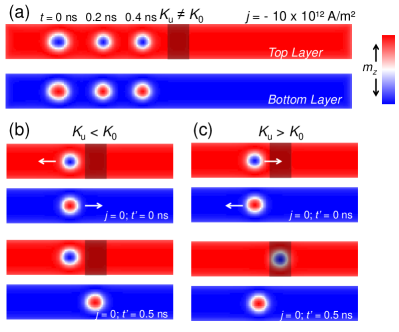
As shown in Fig. 1(a), a spin-polarized current of A m-2 is first applied to drive the SyAF skyrmions into motion, moving about nm in ns and stop near a -nm-long central region of the SyAF racetrack top layer (highlighted in shaded boxes). The -nm-long central region is modified to have a higher or lower PMA constant than that of the rest region of the racetrack . The default PMA constant of the racetrack J m-3 is defined based on the experimental CoPt layers Sampaio_NNANO2013 and used for both top and bottom layers, while PMA constant of the locally modified region and J m-3 and it can be realized by using different materials Purnama_SREP2015 ; Lai_SREP2017 .
Figure 1(b) shows the dynamic behavior of a SyAF skyrmion close to the locally modified region with under zero current (i.e., A m-2). The asymmetry of the PMA in the top layer of the racetrack leads to the motion as well as decoupling of the SyAF skyrmion, even at A m-2. The decoupling of the SyAF skyrmion depends on the strength of the interlayer coupling and may not occur if the relative AFM interlayer coupling is higher than 10-4 (see Supplementary Material). The top-layer skyrmion is repelled from the locally modified region about nm in ns, while the bottom-layer skyrmion is pinned in the locally modified region. A similar phenomenon is observed when the locally modified region has a higher PMA constant, namely, , as shown in Fig. 1(c), where the top-layer skyrmion is pinned in the locally modified region and the bottom-layer skyrmion is repelled from the locally modified region after the decoupling of the SyAF skyrmion. It should be mentioned that there is no skyrmion Hall effect when the skyrmions are decoupled since is adopted for simplicity, as discussed in Ref. Xichao_IEEE2017, . In experiments, it could be difficult to realize the material condition of , which means the skyrmion Hall effect may lead to the decoupling of top-layer and bottom-layer skyrmions. Therefore, a stronger AFM interlayer coupling is usually preferred for experimental samples. On the other hand, if the driving force provided by the spin-polarized current is larger than a certain threshold when , the top-layer and bottom-layer will also be decoupled. Hence, it is important to control the magnitude of the injected current density in experiments.
The results given in Fig. 1 indicates the possibility of manipulating skyrmions by locally modifying the PMA constant in a racetrack, which could be practically realized by using different materials in a well defined region. However, the experimental realization of such a locally modified region demands several steps for the racetrack fabrication. The other possible method is to induce a shape anisotropy that emulates the difference in the PMA constant. In this way, we investigate the dynamic behavior of a SyAF skyrmion near the locally modified region, where the thickness of this region is tuned to be thicker or thinner than the rest region of the racetrack. Such a method has more compatibility with experimental nano-fabrication process, because it demands less lithographic steps and since an ion milling step can be applied to create regions on the racetrack developed with the same material but with different thickness.
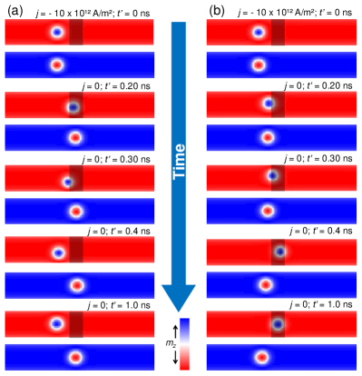
Figure 2(a) shows the response of a SyAF skyrmion to a locally modified region, where the thickness is nm thicker than the rest region of the racetrack. It is found that the top-layer skyrmion is expelled about nm in ns far from the central locally modified region, while the bottom-layer skyrmion is pinned just below the thicker region. Here we find that the thicker region is able to mimic the effect of a locally modified region with lower PMA constant, in this case the antiferromagnetic coupling is weaker, making the anisotropy smaller and it corresponds to the case given in Fig. 1(b), but with a higher efficiency, as the top-layer skyrmion moves about the same distance times faster. Successively, the decrease in the racetrack thickness is studied by locally modifying the central region to be nm thinner than the rest region of the racetrack, opposite to the previous case, the AFM coupling is stronger in the thinner region, behaving as higher value of anisotropy. As shown in Fig. 2(b), when a SyAF skyrmion is close to the thinner central locally modified region ( ns), the top-layer skyrmion is attracted to the central of the modified region ( ns), while the bottom-layer skyrmion is a bit expelled from the locally modified region. In order to understand why the local modifications of PMA constant and shape anisotropy (i.e., thickness) in the racetrack are able to induce the SyAF skyrmion decoupling and pin or expel top-layer/bottom-layer skyrmions, we continue to investigate the in-plane magnetization configurations of the SyAF racetrack.
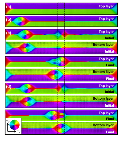
Figure 3 shows the in-plane magnetization configurations for different steps, which are very small and not noticeable in Fig. 1 and Fig. 2 presenting the three-dimensional magnetization. The in-plane magnetization configuration of the ground state of the racetrack is given in Fig. 3(a), and the in-plane magnetization configuration of the relaxed racetrack including a Néel-type SyAF skyrmion is given in Fig. 3(b). As shown in Fig. 3(c), for the locally modified region with or a thinner thickness, two in-plane magnetization areas form in the borders of the locally modified region of the top racetrack, which match the in-plane magnetization configuration of the top-layer skyrmion. Similar behavior is observed in the bottom racetrack, however, the formed in-plane magnetization areas don’t match the in-plane magnetization configuration of the bottom-layer skyrmion. Hence, when the top-layer skyrmion is close to the border of the locally modified region, it is attracted by dipole-dipole interaction (DDI) and pinned by Heisenberg exchange interaction, while the bottom-layer skyrmion is expelled by the same interactions. Figure 3(d) shows the in-plane magnetization configuration for the locally modified region with or a thicker thickness. Here, the in-plane magnetization configurations at the borders of the locally modified region are opposite to that observed in Fig. 3(c), therefore, following the same principle the top-layer skyrmion is expelled from the locally modified region and the bottom-layer skyrmion is attracted and pinning by the locally modified region.
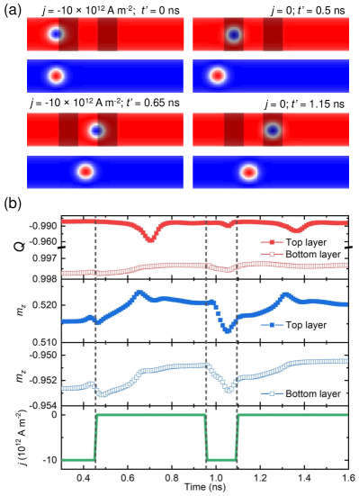
The presented results suggest that it is possible to apply local modifications in the racetrack to generate bits, where the skyrmion is pinned, and in that position a MTJ could be fabricated to sense the skyrmion for information read-out processing. In order to test the shortest bit length we apply two separated spaces where the thickness of the racetrack is reduced by nm. As shown in Fig. 4(a), we demonstrate that the skyrmion can travel between two bits in a controllable manner, where the locally modified regions are able to keep the skyrmion in a desired location for read-out measurement using MTJ Loreto_JMMM2017 . Figure 4(b) shows very small fluctuations in both top-layer and bottom-layer skyrmion topological charges during their motion between the bits, indicating the locally modified region has tiny influence on the skyrmion structure. It is worth mentioning that a single SyAF racetrack can have multiple bits (i.e. skyrmions), however, it is important to control the spacing between neighboring skyrmions in order to avoid skyrmion-skyrmion interaction Xichao_SREP2015A .
In conclusion, we have investigated the dynamic behavior of skyrmions near the locally modified region of a SyAF racetrack, where the PMA constant or shape anisotropy is artificially adjusted. We have shown that it is possible to use the locally modified region to manipulate the skyrmion, such as defining the bit length and setting the right location to develop the read-out MTJ. We found that certain in-plane magnetization configurations are generated at the borders of the locally modified region, which can interact with the skyrmion. The SyAF skyrmion could be decoupled into a top-layer skyrmion and a bottom-layer skyrmion when it is close to the locally modified region, due to the DDI and exchange interaction between skyrmions and in-plane magnetization configurations at the borders of the locally modified region. Depending on the PMA constant or thickness of the locally modified region in relation to the rest region of the racetrack, the skyrmions can be either attracted or expelled by the locally modified region. We have also demonstrated that by using locally modified regions with thinner thickness and with small separation among each other, it is possible to move skyrmions between desired bit locations with very small driving current pulse.
Methods
The micromagnetic simulations are performed with the GPU-accelerated micromagnetic simulator MuMax3, which solves the Landau-Lifshitz-Gilbert (LLG) equation augmented with the adiabatic STT MUMAX ,
| (1) | ||||
where is the reduced magnetization, is the saturation magnetization, is the gyromagnetic ratio with absolute value, is the Gilbert damping parameter, is the non-adiabatic STT strength, is the reduced Planck constant, is the vacuum permeability, is the electron charge, is the polarization ratio of the electric current, and is the effective field. The considered micromagnetic energy terms include the interlayer and intralayer Heisenberg exchange interaction energies, Dzyaloshinskii-Moriya interaction (DMI) energy, PMA energy, applied magnetic field energy, and DDI energy. The energy density of the DMI can be expressed as
| (2) | |||
The third and fourth terms on the right-hand side of Eq. (1) is related to the adiabatic and non-adiabatic STTs provided by the spin-polarized current density in the racetrack.
The simulated racetrack is composed by two ferromagnetic layers with dimensions of nm3, which are separated by a spacer of -nm-thick Ru layer to mimic a SyAF multilayer. The magnetic parameters used in our micromagnetic simulations are adopted from Refs. Sampaio_NNANO2013, ; Yan_NCOMMS2014, ; Xichao_NCOMMS2016, ; Xichao_PRB2016B, ; Xichao_PRB2016A, as follows: the saturation magnetization A m-1; exchange stiffness J m-1; relative AFM interlayer exchange coupling varying from to J m-1; the DMI constant equals J m-2; the PMA constant J m-3, the damping parameter ; the non-adiabatic STT parameter , and the spin polarization factor .
The images of magnetization configurations are obtained by using the MuView software and the topological charges are calculated based on the following definition Wanjun_PHYSREP2017
| (3) |
In theory, the topological charge for a skyrmion is strictly equal to in the continuous model, however, due to the numerical discretization of the micromagnetic simulation process, we have for a skyrmion in the micromagnetic system.
Acknowledgments
This work was partially supported by CAPES (Finance Code 001), CNPq and FAPEMIG (Brazilian agencies). X.Z. acknowledges the support by the Presidential Postdoctoral Fellowship of The Chinese University of Hong Kong, Shenzhen (CUHKSZ). Y.Z. acknowledges the support by the President’s Fund of CUHKSZ, the National Natural Science Foundation of China (Grant No. 11574137), and Shenzhen Fundamental Research Fund (Grant Nos. JCYJ20160331164412545 and JCYJ20170410171958839). M.E. acknowledges the support by the Grants-in-Aid for Scientific Research from JSPS KAKENHI (Grant Nos. JP18H03676, JP17K05490, JP15H05854), and also the support by CREST, JST (Grant No. JPMJCR16F1).
References
References
- (1) S. Parkin, M. Hayashi, and L. Thomas, Science 320, 190 (2008).
- (2) S. Parkin and S.-H. Yang, Nat. Nanotechnol. 10, 195 (2015).
- (3) C. I. L. De Araujo, S. G. Alves, L. D. Buda-Prejbeanu, and B. Dieny, Phys. Rev. Appl. 6, 024015 (2016).
- (4) D. Ralph and M. Stiles, J. Magn. Magn. Mater. 320, 1190 (2008).
- (5) A. Fert, V. Cros, and J. Sampaio, Nat. Nanotechnol. 8, 152 (2013).
- (6) J. Sampaio, V. Cros, S. Rohart, A. Thiaville, and A. Fert, Nat. Nanotechnol. 8, 839 (2013).
- (7) J. Iwasaki, M. Mochizuki, and N. Nagaosa, Nat. Nanotechnol. 8, 742 (2013).
- (8) R. Tomasello, E. Martinez, R. Zivieri, L. Torres, M. Carpentieri, and G. Finocchio, Sci. Rep. 4, 6784 (2014).
- (9) X. Zhang, G. P. Zhao, H. Fangohr, J. P. Liu, W. X. Xia, J. Xia, and F. J. Morvan, Sci. Rep. 5, 7643 (2015).
- (10) N. Nagaosa and Y. Tokura, Nat. Nanotechnol. 8, 899 (2013).
- (11) R. Wiesendanger, Nat. Rev. Mat. 1, 16044 (2016).
- (12) A. Fert, N. Reyren, and V. Cros, Nat. Rev. Mat. 2, 17031 (2017).
- (13) W. Jiang, G. Chen, K. Liu, J. Zang, S. G. Velthuiste, and A. Hoffmann, Phys. Rep. 704, 1 (2017).
- (14) U. K. Roszler, A. N. Bogdanov, and C. Pfleiderer, Nature 442, 797 (2006).
- (15) S. Mühlbauer, B. Binz, F. Jonietz, C. Pfleiderer, A. Rosch, A. Neubauer, R. Georgii, and P. Böni, Science 323, 915 (2009).
- (16) A. O. Leonov and M. Mostovoy, Nat. Commun. 6, 8275 (2015).
- (17) X. Zhang, J. Xia, Y. Zhou, X. Liu, H. Zhang, and M. Ezawa, Nat. Commun. 8, 1717 (2017).
- (18) W. Kang, Y. Huang, X. Zhang, Y. Zhou, and W. Zhao, Proc. IEEE 104, 2040 (2016).
- (19) G. Finocchio, F. Büttner, R. Tomasello, M. Carpentieri, and M. Kläui, J. Phys. D: Appl. Phys. 49, 423001 (2016).
- (20) S. Bhatti, R. Sbiaa, A. Hirohata, H. Ohno, S. Fukami, and S. N. Piramanayagam, Mater. Today. 20, 530, (2017).
- (21) W. Koshibae, Y. Kaneko, J. Iwasaki, M. Kawasaki, Y. Tokura, and N. Nagaosa, Japan. J. Appl. Phys. 54, 053001 (2015).
- (22) H. Du, R. Che, L. Kong, X. Zhao, C. Jin, C. Wang, J. Yang, W. Ning, R. Li, C. Jin, X. Chen, J. Zang, Y. Zhang, and M. Tian, Nat. Commun. 6, 8504 (2015).
- (23) S. Woo, K. M. Song, X. Zhang, Y. Zhou, M. Ezawa, X. Liu, S. Finizio, J. Raabe, N. J. Lee, S.-I. Kim, S.-Y. Park, Y. Kim, J.-Y. Kim, D. Lee, O. Lee, J. W. Choi, B.-C. Min, H. C. Koo, and J. Chang, Nat. Commun. 9, 959 (2018).
- (24) X. Zhang, M. Ezawa, and Y. Zhou, Sci. Rep. 5, 9400 (2015).
- (25) S. Li, W. Kang, Y. Huang, X. Zhang, Y. Zhou, and W. Zhao, Nanotechnology 28, 31LT01 (2017).
- (26) Y. Huang, W. Kang, X. Zhang, Y. Zhou, and W. Zhao, Nanotechnology 28, 08LT02 (2017).
- (27) G. Bourianoff, D. Pinna, M. Sitte, and K. Everschor-Sitte, AIP Adv. 8, 055602 (2018).
- (28) D. Prychynenko, M. Sitte, K. Litzius, B. Krüger, G. Bourianoff, M. Kläui, J. Sinova, and K. Everschor-Sitte, Phys. Rev. Appl. 9, 014034 (2018).
- (29) T. Nozaki, Y. Jibiki, M. Goto, E. Tamura, T. Nozaki, H. Kubota, A. Fukushima, S. Yuasa, and Y. Suzuki, Appl. Phys. Lett. 114, 012402 (2019).
- (30) J. Zang, M. Mostovoy, J. H. Han, and N. Nagaosa, Phys. Rev. Lett. 107, 136804 (2011).
- (31) W. Jiang, X. Zhang, G. Yu, W. Zhang, X. Wang, M. Benjamin Jungfleisch, J. E. Pearson, X. Cheng, O. Heinonen, K. L. Wang, Y. Zhou, A. Hoffmann, and S. G. E. te Velthuis, Nat. Phys. 13, 162 (2017).
- (32) K. Litzius, I. Lemesh, B. Krüger, P. Bassirian, L. Caretta, K. Richter, F. Büttner, K. Sato, O. A. Tretiakov, J. Förster, R. M. Reeve, M. Weigand, I. Bykova, H. Stoll, G. Schütz, G. S. D. Beach, and M. Kläui, Nat. Phys. 13, 170 (2017).
- (33) Y. Zhou and M. Ezawa, Nat. Commun. 5, 4652 (2014).
- (34) W. Jiang, P. Upadhyaya, W. Zhang, G. Yu, M. B. Jungfleisch, F. Y. Fradin, J. E. Pearson, Y. Tserkovnyak, K. L. Wang, O. Heinonen, S. G. E. te Velthuis, and A. Hoffmann, Science 349, 283 (2015).
- (35) G. Yu, P. Upadhyaya, Q. Shao, H. Wu, G. Yin, X. Li, C. He, W. Jiang, X. Han, P. K. Amiri, and K. L. Wang, Nano Lett. 17, 261 (2017).
- (36) F. Büttner, I. Lemesh, M. Schneider, B. Pfau, C. M. Günther, P. Hessing, J. Geilhufe, L. Caretta, D. Engel, B. Krüger, J. Viefhaus, S. Eisebitt, and G. S. D. Beach, Nat. Nanotechnol. 12, 1040 (2017).
- (37) S. Woo, K. M. Song, X. Zhang, M. Ezawa, Y. Zhou, X. Liu, M. Weigand, S. Finizio, J. Raabe, M.-C. Park, K.-Y. Lee, J. W. Choi, B.-C. Min, H. C. Koo, and J. Chang, Nat. Electron. 1, 288 (2018).
- (38) I. Purnama, W. L. Gan, D. W. Wong, and W. S. Lew, Sci. Rep. 5, 10620 (2015).
- (39) P. Lai, G. P. Zhao, H. Tang, N. Ran, S. Q. Wu, J. Xia, X. Zhang, and Y. Zhou, Sci. Rep. 7, 45330 (2017).
- (40) X. Zhang, J. Xia, Y. Zhou, D. Wang, X. Liu, W. Zhao, and M. Ezawa, Phys. Rev. B 94, 094420 (2016).
- (41) X. Zhang, Y. Zhou, and M. Ezawa, Sci. Rep. 6, 24795 (2016).
- (42) J. Barker and O. A. Tretiakov, Phys. Rev. Lett. 116, 147203 (2016).
- (43) X. Zhang, Y. Zhou, and M. Ezawa, Nat. Commun. 7, 10293 (2016).
- (44) X. Zhang, M. Ezawa, and Y. Zhou, Phys. Rev. B 94, 064406 (2016).
- (45) X. Zhang, J. Xia, G. P. Zhao, X. Liu, and Y. Zhou, IEEE Tran. Magn. 53, 1500206 (2017).
- (46) R. P. Loreto, W. A. Moura-Melo, A. R. Pereira, X. Zhang, Y. Zhou, M. Ezawa, and C. I. de Araujo, J. Magn. Magn. Mater. 455, 25 (2018).
- (47) A. Vansteenkiste, J. Leliaert, M. Dvornik, M. Helsen, F. Garcia-Sanchez, and B. Van Waeyenberge, AIP Adv. 4, 107133 (2014).
Author Contributions
C.I.L.A coordinated the project. R.P.L. and C.I.L.A performed the simulation. C.I.L.A, R.P.L. and X.Z. prepared the manuscript with input from Y.Z., M.E. and X.L. All authors discussed the results and reviewed the manuscript.
Competing Financial Interests
The authors declare no competing financial interests.