Third-order nonlinearity by the inverse Faraday effect in planar magnetoplasmonic structures
Abstract
We predict a new type of ultrafast third-order nonlinearity of surface plasmon polaritons (SPP) in planar magneto-plasmonic structures caused by the inverse Faraday effect (IFE). Planar SPPs with a significant longitudinal component of the electric field act via the IFE as an effective transverse magnetic field. Its response to the plasmon propagation leads to strong ultrafast self-action which manifests itself through a third-order nonlinearity. We derive a general formula and analytical expressions for the IFE-related nonlinear susceptibility for two specific planar magneto-plasmonic structures from the Lorentz reciprocity theorem. Our estimations predict a very large nonlinear third-order nonlinear susceptibility exceeding those of typical metals such as gold.
pacs:
42.65.-k, 73.20.Mf, 75.78.jp, 78.20.LsI Introduction
Nonlinear optical effects can be enhanced by plasmonic structures supporting local field enhancement and inhomogeneity on the nanoscale Kauranen and Zayats (2012). In particular, nonlinear propagation of surface plasmon polaritons (SPPs) in plasmonic waveguides has attracted attention to achieve ultrafast phase modulation and due to its implication for plasmonic systemsMacDonald et al. (2008); Mrejen et al. (2015). Different types of nonlinear plasmonic waveguides has been theoretically investigated, such as nonlinear plasmonic planar waveguides Marini and Biancalana (2013); Skryabin et al. (2011); De Leon et al. (2014a); Baron et al. (2015), metal nanowires Marini et al. (2013); Im et al. (2016), slot waveguides Davoyan et al. (2008) and periodic waveguides Ye et al. (2010); Sukhorukov et al. (2014). In such plasmonic waveguides, the effective nonlinearity originates from the third-order optical Kerr effect describing a refractive index change proportional to the square of the absolute value of the electric field strength.
Recently, manipulation of the magnetic order of thin magnetic films by ultrashort pulses based on the inverse Faraday effect (IFE) has attracted much attention because of its potential impact for future data storage, spintronics Kimel et al. (2005); Stanciu et al. (2007); Radu et al. (2011) and improved imaging Malinowski et al. (2008); von Korff Schmising et al. (2014); Büttner et al. (2015); von Korff Schmising et al. (2015). Using field enhancement plasmonic structures has also been studied for the enhancement of the IFE Smolyaninov et al. (2005); Belotelov and Zvezdin (2012); Hamidi et al. (2015) and to achieve control of the magnetization of ferromagnetic material on the nanoscale von Korff Schmising et al. (2015). On the other hand, in the last years much effort has been devoted to study new ways to control the properties of surface plasmons using external magnetic fields in ferromagnetic dielectric Belotelov et al. (2011) or metal Temnov et al. (2016) layers. In these experiments the magnetization induced by the external magnetic field leads to a change of the plasmon wavenumber which can be measured by a plasmonic double-slit interferometer.
In this paper we theoretically predict a new type of ultrafast third-order nonlinearity of surface plasmon polaritons in planar ferromagnetic plasmonic structures related with the inverse Faraday effect. In a plasmonic layer, planar SPP with a longitudinal component of the electric field induce a magnetization which leads to a third-order nonlinear polarization. This kind of nonlinearity plays in the plasmon propagation analog effects as the optical Kerr effect but it originates from a different physical mechanism. We derive a formula for the IFE-related nonlinear susceptibility and explicit analytical expressions for two kinds of planar magneto-plasmonic structures. The IFE-related nonlinear susceptibility differs from the traditional Kerr-related nonlinear susceptibility by its magnitude, frequency dependence and its inherent dependence on the material parameters.
II IFE-related third-order nonlinear susceptibility for planar magneto-plasmonic structures
In a bulk ferromagnetic material, a static external magnetic field leads to a magnetization Landau et al. (1995).In such material the vector of the electric displacement depends on the external magnetic field and is described by
| (1) |
where the relative permittivity tensor is expressed as
| (5) |
and describes the magneto-optical susceptibility. From this relation one can see that the optical polarization has a contribution proportional to the magnetization The consequence of this relationship is the magneto-optical Faraday effect leading to a polarization rotation when a linearly polarized light beam is transmitted through a magneto-optical medium under an external magnetic field. The non-diagonal terms in the permittivity tensor describes also the changes to light reflected from a magnetized surface (magneto-optical Kerr effect, MOKE). Pump-probe measurement in nickel films has shown that fast subpicosecond demagnetization can be induced by femtosecond optical pulses Beaurepaire et al. (1996).
A magnetic material irradiated by circularly polarized light induces a magnetization along the wave vector Pitaevskii (1961); der Ziel et al. (1965) which is called the inverse Faraday effect (IFE). The light-induced magnetization can be expressed as
| (6) |
where is a material dependent constant related with the Verdet constant and can be understood as the IFE-related third-order nonlinear susceptibility of the bulk ferromagnetic material. Left- and right-handed polarization waves induce magnetization of opposite signs.
Light cannot penetrate into a thin metallic layer, but under appropriate conditions (as e.g. by using the Kretschman configuration for p-polarized light) surface plasmon-polaritons (SPP) can be excited moving along the surface. Plasmons exhibit a longitudinal component of the electric field, therefore the chirality of plasmons do not vanishes. This means that even for a linearly polarized input beam a magnetization can be induced by plasmons, but the polarization of the plasmon is not circularly polarized.
Substituting the expression (6) for the magnetization into relation (1) we can see that the IFE leads to a third-order nonlinear polarization caused by a different physical mechanism than the optical Kerr effect. For the derivation of the IFE-related nonlinear susceptibility of a planar plasmonic structures including a ferromagnetic layer, we use a formalism similar as in Ref. Im et al. (2016). In a planar waveguides the electromagnetic field is confined in different spatial modes Maier (2007), but only the fundamental mode plays here a role. The mode expansion for the electric and the magnetic fields in the plasmonic waveguide can be expressed as , where c.c. signifies the complex conjugate. Below, we restrict ourselves to the time-independent amplitude for the fundamental mode, , which can be expressed as
| (7) |
| (8) | |||||
Here and are the coordinate and the unit vector in the direction of propagation, is the position vector in the transverse plane, is defined as , where the integral is performed over the transverse plane, is the SPP propagation constant, is normalized so that the is equal to the power flow along the direction , and and describe the spatial transverse distribution of the mode. We start from the Lorentz reciprocity theorem Snyder and Love (1983)
| (9) | |||||
where and are two arbitrary guided modes. Now we substitute for and the unperturbed backward propagating field and the perturbed forward propagating field depending on an external quasi-static transverse magnetic field , correspondingly. The external magnetic field induces a magnetization in the transverse y-direction and leads to a perturbation for the mode distribution. In the first order of perturbation Eq. (9) leads to the following equation describing the amplitude of the plasmonic field:
| (10) |
where is the linear loss coefficient and
| (11) |
is the shift of the plasmon wavenumber induced by the external magnetic field. and are the wave impedance and the light wavenumber in vacuum, respectively.
Now we consider an alternative arrangement without external static magnetic field but with a laser pulse directed to the planar magneto-optical structure and acting as an effective magnetic field via the IFE. The SPP mode of the planar plasmonic waveguide induces a magnetization into the transverse y-direction. From Eq. (6) the nonlinear magnetization is expressed as
| (12) |
with . If we substitute Eq. (12) into Eq. (10) and (11), we find
| (13) |
where
| (14) |
is the effective nonlinear propagation coefficient.
III Ferromagnetic dielectric/metal interface
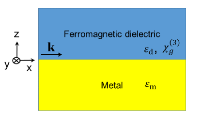
Let us derive more explicit analytical formulas for two typical types of planar magneto-plasmonic interfaces. First, we consider a ferromagnetic dielectric/metallic interface as shown in the Fig. 1.
In the case that an external magnetic field is present leading to a magnetization , by substituting the analytical expression of the fundamental TM mode distribution of a single interface Eq. (2.10)-(2.14) of Ref. Maier (2007) into Eq. (11) we can derive a plasmon wavenumber shift given by
| (15) |
Eq. (15) is in agreement with Eq. (4) of Ref. Belotelov et al. (2011) used for the description of the control of the optical phase of a plasmon in a magneto-optical interferometer.
For the case without external magnetic field but with an incident laser pulse the substitution of the analytical mode distribution for the fundamental mode of the planar plasmonic waveguide Maier (2007) into Eq. (14) yields the following expression:
| (16) |
Here, high quality of the plasmonic metal was assumed so that .
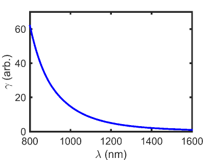
Fig. 2 shows the wavelength-dependence of the nonlinear coefficient . Here, we used the frequency-depending experimental data for the permittivity of gold Johnson and Christy (1972) as . The wavelength-dependence of the nonlinear susceptibility of the bulk ferromagnetic dielectric is disregarded.
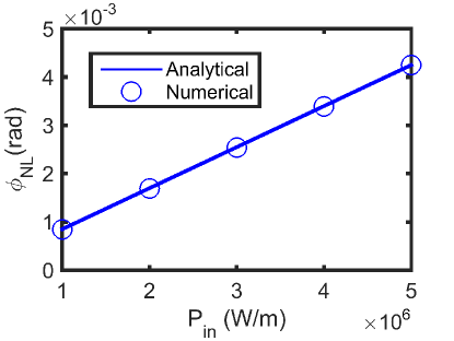
Fig. 3 shows the power-dependence of the nonlinear phase shift for a wavelength of 1550 nm and a propagation distance of nm for an interface between gold and a ferromagnetic dielectric. For the calculation of the absolute values of the nonlinear phase shift, we assumed and . The blue line represents with the analytical prediction of by Eq. (16). The analytical prediction is in good agreement with the numerically determined phase shift (the blue circles in Fig. 4), obtained by numerical solutions of the Maxwell equations in the frequency domain (analogous as in Ref. Im et al. (2016)).
If we consider in the infrared region, Eq. (16) is simplified to
| (17) |
The IFE-related nonlinear susceptibility is predicted to be linearly dependent on the permittivity of the dielectric material as can be seen in Eq. (17). Note that for the same material besides the IFE-related third-order nonlinearity a different type of third-order nonlinearity exist caused by the optical Kerr effect. Substituting the mode distribution of the planar interface to Eq. (9) of Ref. Im et al. (2016), the Kerr-related nonlinear susceptibility of the planar interface is given by
| (18) |
which is independent on the permittivity of the dielectric . is here the Kerr-related nonlinear susceptibility of the bulk dielectric.
IV Dielectric/hybrid metal-ferromagnetic interface
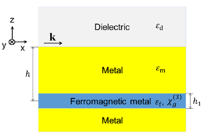
Next, we consider the dielectric/hybrid metal-ferromagnetic interface as shown in the Fig. 4. In particular such structure has been applied for active magneto-plasmonic micro-interferometry Temnov et al. (2010).
By substituting the mode distribution of a single interface Maier (2007)into Eq. (11) for the case of the presence of an external magnetic field as in Temnov et al. (2010) we obtain for the plasmon wavenumber shift
| (19) |
Here, , and is the diagonal permittivity, depth and thickness of the ferromagnetic material, respectively, and . The Eq. (19) coincides to Eq. (2) of Ref. Temnov et al. (2010).
Next we consider the case that an incident laser field induces an opto-magnetic field by the IFE. If we substitute the mode distribution to Eq. (14) and assume ,
| (20) | |||||
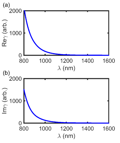
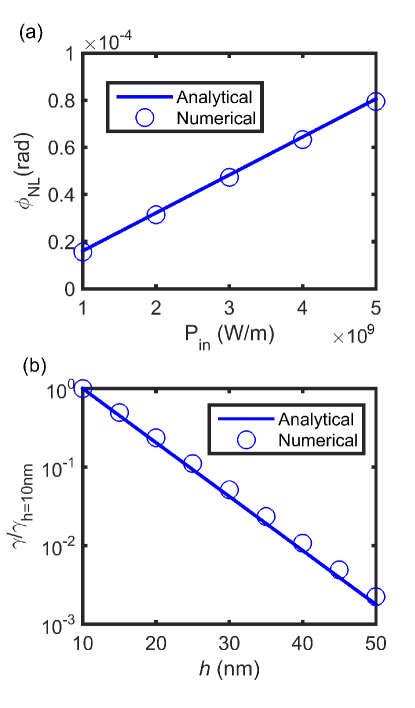
Fig. 5 shows the wavelength-dependence of the nonlinear coefficient for the interface between the Au-Co-Au hybrid structure and air. Here, we used the experimental data for the permittivity spectra of gold Johnson and Christy (1972) and cobalt Johnson and Christy (1974) as and , respectively. Fig. 6(a) shows the power-dependence of the nonlinear phase shift for a wavelength of 808 nm and a propagation distance of =5000 nm for the interface between the Au-Co-Au hybrid structure and air. For calculation of the absolute values of the nonlinear phase shift, we assumed . The analytical prediction (the blue line) is in good agreement with the numerical simulation (blue circles). Fig. 6(b) shows the exponential dependence of the nonlinear susceptibility on the position of the cobalt layer in agreement with the numerical simulation, which demonstrates that the nonlinearity originates from the thin cobalt layer.
If we consider in the infrared region, Eq. (20) is simplified to
| (21) |
As seen the IFE-related nonlinear susceptibility depends on the -power of the permittivity of the dielectric material. For example, by exchanging the air with the garnet in the hybrid structure Fig. 4, the IFE-related nonlinear susceptibility is enhanced by more than 1000 times. In Ref. Martín-Becerra et al. (2012) a possibility has been discussed to increase the magneto-optical effect by increasing , but the drawback of this approach is the simultaneous reduction of the SPP propagation length. We note, however, the 4th-power-depenedence of the IFE-related nonlinear susceptibility on dominates the reduction of the SPP propagation length. Substituting the mode distribution to Eq. (9) of Ref. Im et al. (2016), we find for the Kerr-related nonlinear susceptibilities of the structure in Fig. 4
| (22) |
where is the Kerr-related nonlinear susceptibility in the thin layer with the thickness .
Let us compare the magnitude of the nonlinear phase shift of the hybrid structure of Fig. 4 (including a ferromagnetic metallic layer) with the ferromagnetic dielectric/metal interface in Fig. 1. As seen from the comparison of Fig. 3 with Fig. 6(a) the nonlinear phase shift in the ferromagnetic dielectric/metal interface is by orders of magnitude larger. The reason is that in a ferromagnetic dielectric much more energy is distributed than in a metallic structure.
Note that recently magnetization-induced second harmonic generation has been studied in Ref. Zheng et al. (2015); Razdolski et al. (2016) arising in magneto-plasmonic systems in the presence of an external magnetic field. The here studied third-order IFE-related nonlinear effect qualitatively differ from this second-order nonlinear effect and do not require any external magnetic field.
Let us discuss the time-response of the IFE-related nonlinearity based on the magnetization dynamics in ferromagnetic thin films. The relaxation process of electrons and spin systems in a ferromagnetic thin films after excitation with a femtosecond pulse is related with a number of processes in the interaction of light with the spin degrees of freedom of electrons and the thermalization of electron in such system. In Ref. Beaurepaire et al. (1996) it was found that a nickel thin film can be demagnetized after excitation by a sub-100fs laser pulse. Several studies confirmed later this result. Note that the underlying mechanism in time-domain magnetization dynamics is still in discussion Zhang et al. (2009); Carva et al. (2011).
V Discussions and Conclusions
Let us estimate the order of magnitudes of parameters for the IFE-related third-order nonlinearity of SPPs in planar magneto-plasmonic structures. From the expression for the IFE-induced effective magnetic field we can predict that the nonlinear susceptibility of a bulk-ferromagnetic material is on the order of , where is the magneto-optical susceptibility. If is on the order of Vahaplar et al. (2012) for a ferromagnetic material, is on the order of . This presents a very strong third-order nonlinear susceptibility compared to the Kerr-nonlinearity of typical dielectric materials with on the order of . is also larger than the measured of gold on the order of at the wavelengths of 630 nm Rotenberg et al. (2007) and 796.5 nm De Leon et al. (2014b). If we assume a structure depth on the order of a half wavelength which does not induce noticeable deterioration to the device performance Cai et al. (2009), from Eq. (16) we can estimate a huge nonlinear coefficient on the order of .
In conclusion, in this paper we predicted a new type of ultrafast third–order nonlinearity of SPPs in planar magneto-plasmonic structures based on the induced effective magnetic field by the inverse Faraday effect and its response on the plasmon propagation. We derived a formula for the IFE-related nonlinear susceptibility for two planar magneto-plasmonic structures from the Lorentz reciprocity theorem and analytical expressions for the nonlinear coefficients that describe a strong self-action of the SPPs manifesting in a nonlinear phase shift and a self-induced absorption. Our theoretical prediction of the IFE-related nonlinearity indicates a very large, ultrafast effective third-order susceptibility exceeding those of typical metals like gold. The results presented here could have important implication for the study of magneto-plasmonic systems as well as for applications in nonlinear plasmonics as e.g. to achieve ultrafast plasmonic modulation.
References
- Kauranen and Zayats (2012) M. Kauranen and A. V. Zayats, Nat. Photonics 6, 737 (2012).
- MacDonald et al. (2008) K. F. MacDonald, Z. L. Samson, M. I. Stockman, and N. I. Zheludev, Nat. Photonics 3, 55 (2008).
- Mrejen et al. (2015) M. Mrejen, H. Suchowski, T. Hatakeyama, C. Wu, L. Feng, K. O’Brein, Y. Wang, and X. Zhang, Nat. Commun. 6, 7565 (2015).
- Marini and Biancalana (2013) A. Marini and F. Biancalana, Phys. Rev. Lett. 110, 243901 (2013).
- Skryabin et al. (2011) D. V. Skryabin, A. Gorbach, and A. Marini, J. Opt. Soc. Am. B 28, 109 (2011).
- De Leon et al. (2014a) I. De Leon, J. E. Sipe, and R. W. Boyd, Phys. Rev. A 89, 013855 (2014a).
- Baron et al. (2015) A. Baron, T. B. Hoang, C. Fang, M. H. Mikkelsen, and D. R. Smith, Nat. Nanotechnol. 91, 195412 (2015).
- Marini et al. (2013) A. Marini, M. Conforti, G. D. Valle, H. W. Lee, W. C. T. X. Tran, M. A. Schmidt, S. Longhi, P. S. J. Russell, and F. Biancalana, New J. of Phys. 15, 013033 (2013).
- Im et al. (2016) S.-J. Im, K.-S. Ho, Q.-Q. Wang, A. Husakou, and J. Herrmann, Opt. Express 24, 6162 (2016).
- Davoyan et al. (2008) A. R. Davoyan, I. V. Shadrivov, and Y. S. Kivshar, Opt. Express 16, 21209 (2008).
- Ye et al. (2010) F. Ye, D. Mihalache, B. Hu, and N. C. Panoiu, Phys. Rev. Lett. 104, 106802 (2010).
- Sukhorukov et al. (2014) A. A. Sukhorukov, A. S. Solntsev, S. S. Kruk, D. N. Neshev, and Y. S. Kivshar, Opt. Lett. 39, 462 (2014).
- Kimel et al. (2005) A. Kimel, A. Kirilyuk, P. Usachev, R. P. Pisarev, A. M. Balbashov, and T. Rasing, Nature 435, 655 (2005).
- Stanciu et al. (2007) C. D. Stanciu, F. Hansteen, A. V. Kimel, A. Kirilyuk, A. Tsukamoto, A. Itoh, and T. Rasing, Phys. Rev. Lett. 99, 047601 (2007).
- Radu et al. (2011) I. Radu, K. Vahaplar, C. Stamm, T. Kachel, N. Pontius, H. A. Durr, T. A. Ostler, J. Barker, R. F. Evans, R. W. Chantrell, A. Tsukamoto, A. Itoh, A. Kirilyuk, T. Rasing, and A. V. Kimel, Nature 472, 205 (2011).
- Malinowski et al. (2008) G. Malinowski, F. D. Longa, J. H. H. Rietjens, P. V. Paluskar, R. Huijink, H. J. M. Swagten, and B. Koopmans, Nat. Phys. 4, 855 (2008).
- von Korff Schmising et al. (2014) C. von Korff Schmising, B. Pfau, M. Schneider, C. M. Günther, M. Giovannella, J. Perron, B. Vodungbo, L. Müller, F. Capotondi, E. Pedersoli, N. Mahne, J. Lüning, and S. Eisebitt, Phys. Rev. Lett. 112, 217203 (2014).
- Büttner et al. (2015) F. Büttner, C. Moutafis, M. Schneider, B. Krüger, C. Günther, J. Geilhufe, C. von Korff Schmising, J. Mohanty, B. Pfau, S. Schaffert, A. Biesig, M. Foerster, T. Schulz, C. Vaz, J. Franken, H. Swagten, M. Kläui, and S. Eisebitt, Nat. Phys. 11, 225 (2015).
- von Korff Schmising et al. (2015) C. von Korff Schmising, M. Giovannella, D. Weder, S. Schaffert, J. Webb, and S. Eisebitt, New J. of Phys. 17, 033047 (2015).
- Smolyaninov et al. (2005) I. I. Smolyaninov, C. C. Davis, V. N. Smolyaninova, D. Schaefer, J. Elliott, and A. V. Zayats, Phys. Rev. B 71, 035425 (2005).
- Belotelov and Zvezdin (2012) V. I. Belotelov and A. K. Zvezdin, Phys. Rev. B 86, 155133 (2012).
- Hamidi et al. (2015) S. Hamidi, M. Razavinia, and M. Tehranchi, Optics Comm. 338, 240 (2015).
- Belotelov et al. (2011) V. I. Belotelov, I. A. Akimov, M. Pohl, V. A. Kotov, S. Kasture, A. S. Vengurlekar, A. V. Gopal, D. R. Yakovlev, A. K. Zvezdin, and M. Bayer, Nat. Nanotechnol. 6, 370 (2011).
- Temnov et al. (2016) V. V. Temnov, I. Razdolski, T. Pezeril, D. Makarov, D. Seletskiy, A. Melnikov, and K. A. Nelson, J. Opt. 18, 093002 (2016).
- Landau et al. (1995) L. D. Landau, E. M. Lifshits, and L. P. Pitaevskii, Electrodynamics of continuous media (Butterworth-Heinemann, Oxford, England, 1995).
- Beaurepaire et al. (1996) E. Beaurepaire, J.-C. Merle, A. Daunois, and J.-Y. Bigot, Phys. Rev. Lett. 76, 4250 (1996).
- Pitaevskii (1961) L. P. Pitaevskii, Sov. Phys. JETP 12, 1008 (1961).
- der Ziel et al. (1965) J. P. V. der Ziel, P. S. Pershan, and L. D. Malmstrom, Phys. Rev. Lett. 15, 190 (1965).
- Maier (2007) S. A. Maier, Plasmonics: Fundamentals and Applications (Springer, New York, 2007).
- Snyder and Love (1983) A. Snyder and J. D. Love, Optical Waveguide Theory (Chapman and Hall, London, 1983).
- Johnson and Christy (1972) P. B. Johnson and R. W. Christy, Phys. Rev. B 6, 4370 (1972).
- Temnov et al. (2010) V. V. Temnov, G. Armelles, U. Woggon, D. Guzatov, A. Cebollada, A. García-Martín, J. M. García-Martín, T. Thomay, A. Leitenstorfer, and R. Bratschitsch, Nat. Photonics 4, 107 (2010).
- Johnson and Christy (1974) P. B. Johnson and R. W. Christy, Phys. Rev. B 9, 5056 (1974).
- Martín-Becerra et al. (2012) D. Martín-Becerra, V. V. Temnov, T. Thomay, A. Leitenstorfer, R. Bratschitsch, G. Armelles, A. García-Martín, and M. U. González, Phys. Rev. B 86, 035118 (2012).
- Zheng et al. (2015) W. Zheng, X. Liu, A. T. Hanbicki, B. T. Jonker, and G. Lüpke, Opt. Mater. Express 5, 2597 (2015).
- Razdolski et al. (2016) I. Razdolski, D. Makarov, O. G. Schmidt, A. Kirilyuk, T. Rasing, and V. V. Temnov, ACS Photon. 3, 179 (2016).
- Zhang et al. (2009) G. P. Zhang, W. Hubner, G. Lefkidis, Y. H. Bai, and T. F. George, Nat. Phys. 5, 499 (2009).
- Carva et al. (2011) K. Carva, M. Battiato, and P. M. Oppeneer, Nat. Phys. 7, 665 (2011).
- Vahaplar et al. (2012) K. Vahaplar, A. M. Kalashnikova, A. V. Kimel, S. Gerlach, D. Hinzke, U. Nowak, R. Chantrell, A. Tsukamoto, A. Itoh, A. Kirilyuk, and T. Rasing, Phys. Rev. B 85, 104402 (2012).
- Rotenberg et al. (2007) N. Rotenberg, A. D. Bristow, M. Pfeiffer, M. Betz, and H. M. van Driel, Phys. Rev. B 75, 155426 (2007).
- De Leon et al. (2014b) I. De Leon, Z. Shi, A. C. Liapis, and R. W. Boyd, Opt. Lett. 39, 2274 (2014b).
- Cai et al. (2009) W. Cai, J. White, and M. Brongersma, Nano Lett. 9, 4403 (2009).