∎
11email: timo.kamppinen@aalto.fi
22institutetext: Low Temperature Laboratory, Department of Applied Physics, School of Science, Aalto University, Espoo 02150, Finland
Nanomechanical resonators for cryogenic research
Abstract
Suspended aluminium nanoelectromechanical resonators have been fabricated, and the manufacturing process is described in this work. Device motion is driven and detected with a magnetomotive method. The resonance response has been measured at temperature in vacuum and low pressure 4He gas. At low oscillation amplitudes the resonance response is linear, producing Lorentzian line shapes, and -values up to 4400 have been achieved. At higher oscillation amplitudes the devices show nonlinear Duffing-like behavior. The devices are found to be extremely sensitive to pressure in 4He gas. Such device is a promising tool for studying properties of superfluid helium.
Keywords:
NEMS Sensors 4He Quantized vortices1 Introduction
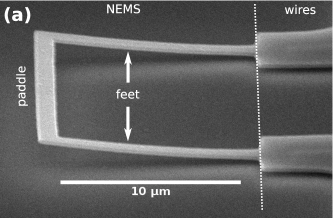
In cryogenic fluids like 4He and 3He, immersed oscillating objects such as tuning forks, wires, grids and spheres have proven to be useful and multifunctional tools acting as thermometers, bolometers, pressure gauges, viscometers, as well as generators and detectors of turbulence, cavitation and sound Blazkova2008 ; Blaauwgeers2007 ; Pentti2011 ; Salmela2011 . Fluid properties are usually determined from measured changes in mechanical resonance response including resonance frequency, line width, amplitude and certain non-linear effects (for example, nonlinear drag force resulting from turbulence). For high sensitivity, a resonator with low mass and spring constant together with a high -value is required. Modern micro- and nanofabrication techiques have enabled creation of ultra sensitive probes of the quantum fluids Bradley2017 ; Zheng2016 ; Defoort2016 . We are pursuing sensitivity to the force resulting from dynamics of a single quantized vortex attached to a mechanical resonator. This would allow us to study many interesting phenomena, such as Kelvin-wave cascade on a single quantized vortex in 3He and 4He Vinen2003 ; Baggaley2014 ; Kondaurova2014 ; the role of vortex-core-bound fermions in the vortex dynamics in 3He-B Makinen2018 ; Kopnin1991 ; vortex friction due to the chiral anomaly, and the synthetic electromagnetic fields created by vortex motion in Weyl superfluid 3He-A Bevan1997 . To reach this goal, we have fabricated suspended aluminium nanoelectromechanical (NEMS) resonators with typical effective mass , dimensions and rectangular cross section of (see Fig. 1).
2 Methods
2.1 Fabrication process
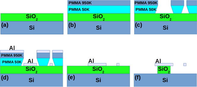
The fabrication process of the NEMS devices is presented schematically in Fig. 2. We start with a high purity (resistivity ) silicon chip with of SiO2 on top. First, the chip is cleaned in solvent baths (ethyl pyrrolidinone, acetone and isopropanol) with ultrasound, and a positive tone PMMA (polymethyl methacrylate, 50k/950k) bilayer is spin coated on top of the chip. The device pattern is written by electron beam lithography and developed in MIBK:IPA (1:3) solution. After a brief () O2 plasma cleaning, a thick aluminum layer is deposited on the surface of the chip with an electron beam evaporator. To release the vibrating structures, the sacrificial SiO2 layer is etched with isotropic dry HF vapor process. The released structure has typically some upward curvature, as seen in Fig. 1. It originates from internal stress formed in the metal layer due to temperature changes during metal deposition. When the device is released the cantilever feet deform and some of the internal stress in the freestanding parts relieves deformation .
2.2 Measurement scheme
Magnetomotive measurement.
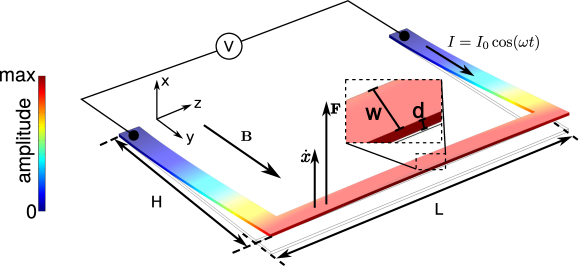
The magnetomotive measurement scheme is depicted in Fig. 3. When a constant magnetic field is applied in the -direction, perpendicular to the paddle of length , and an AC current is fed through the device, the paddle experiences a Lorentz force in the -direction. The force drives the resonator into oscillatory motion at the frequency . The first eigenmode of the nanomechanical resonator corresponds to out-of-plane and in-phase oscillation of the two cantilever feet connected by a rigid paddle. In this configuration, the motion of the paddle through the magnetic field generates via electromotive force a voltage across the paddle, where is the velocity of the paddle. The oscillation amplitudes of velocity and displacement are related as .
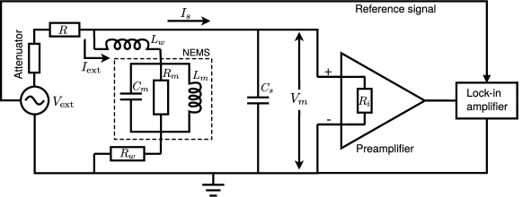
Measurement circuit.
A schematic of the measurement circuitry is presented in Fig. 4. The excitation current is generated by an arbitrary-waveform generator, followed by a attenuator and a resistor connected in series with the resonator. The voltage over the resonator is amplified with a preamplifier and measured with a lock-in amplifier, which is phase-locked with the generator. , and present the resistance, inductance and stray capacitance of the device, wires and connected devices, and they contribute to a background signal, which is a linear function of frequency for narrow sweeps around the mechanical resonance. This background is subtracted from the measured response in further analysis of the results.
Experimental setup.
The NEMS devices are wire-bonded to a printed circuit board (PCB) with aluminum wires. The PCB is attached to a copper plate, which is installed in vacuum chamber of a dipstick setup. The chamber is immersed in liquid 4He bath, which provides a stable temperature enabling the use of a superconducting magnet and ensuring low thermal noise. Twisted pairs of copper wires carry the signals between the PCB at and the room temperature end of the dipstick, and standard coaxial cables are used to connect the dipstick to the measurement electronics at room temperature. The magnetic field is produced by a superconducting solenoid.
2.3 Theorethical background
Resonance response.
A NEMS device can be treated as damped oscillator driven by an external force . At sufficiently small oscillation amplitudes, harmonic approximation is valid. The equation of motion is
| (1) |
where , , are the displacement, velocity and acceleration of the paddle, is the drag coefficient (in units rad/s), and is the natural frequency of the mechanical oscillator where and are the effective mass and the spring constant. The solution in the frequency domain is given by the Lorentzian functions for absorption and dispersion
| (2) |
respectively. The maximum amplitude is obtained at the resonance frequency , and the full width at half height of the absorption curve is . The -value is defined as , and it holds for the maximum displacement at resonance that Schmid2016 . At large oscillation amplitudes the response becomes Duffing-like nonlinear Collin2010 and shows hysteresis depending on the direction of the frequency sweep. In practice, we measure the voltages and , which we convert to velocity or displacement of the beam.
Kinetic damping.
The force experienced by an oscillating body moving through low pressure gas in the ballistic regime is due to momentum transfer in collisions with individual gas molecules. The moving body experiences kinetic damping squeeze_film
| (3) |
where is the effective mass, is the average velocity of the gas molecules, is the pressure and is the scattering cross section, which is obtained by weighting the area with the velocity profile over the surface. For the NEMS devices considered here, we have .
Squeeze film force.
The vicinity of the Si surface to the oscillating NEMS device results in a squeeze film force, which arises due to compression and decompression of the gas in the narrow gap between the oscillator and the surface. The force has an elastic and a dissipative contribution, and in the ballistic regime the corresponding terms are
| (4) |
| (5) |
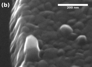
where is the gap between device and Si surface estimated from SEM figures, and
is the diffusion time of 4He gas out of the narrow gap at temperature squeeze_film . Comparing the magnitudes of the two additional damping terms in 4He gas, we get , so squeeze film damping is the dominant loss mechanism of these two. The resonance frequency is expected to increase from the vacuum value as due to the small additional spring constant . The expected frequency shift for sample 4UV is and the increase in line width is expected to be in 4He gas at temperature.
3 Results
Mechanical properties.
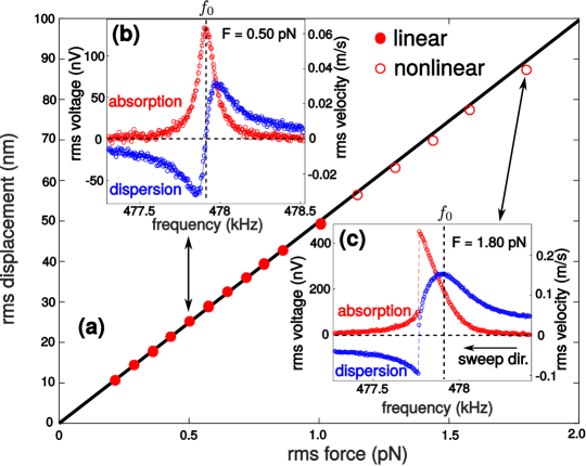
The geometrical dimensions and measured properties of the NEMS devices are tabulated in Table 1. The resonance frequency and line width are obtained from Lorentzian fits (Eq. 2) to linear resonance spectra, such as shown in Fig. 5. The highest -value obtained in this work is at temperature in vacuum. The measured -values are in line with typical values reported for NEMS resonators of this size in the literature. Maximum displacement amplitude as a function of the excitation force for sample 4UN is shown in Fig. 5. The effective mass and the spring constant are extracted from the slope of the linear dependence using the relations .
| Property | 4NN | 4UN | 4UV | description (determined from) |
| () | 16.9 | 17.0 | 20.7 | paddle length (SEM micrographs) |
| () | 11.0 | 11.1 | 11.0 | feet length (SEM micrographs) |
| () | 1.11 | 1.12 | 1.10 | beam width (SEM micrographs) |
| () | 150 | 150 | 150 | beam thickness (crystal monitor of evaporator) |
| () | 475.43 | 477.92 | 430.50 | resonance frequency (measurement) |
| 4407 | 3894 | 3115 | Q-value (measurement) | |
| () | 0.08751 | 0.07724 | 0.2262 | effective spring constant (measurement) |
| () | 9.81 | 8.57 | 30.9 | effective mass (measurement) |
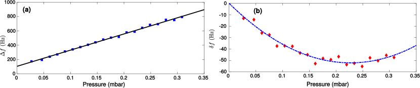
Pressure dependence.
We have measured pressure dependence of the resonance response for sample 4UV, and the results are presented in Fig. 6. The increase in width with pressure is roughly half the value predicted by theory (Eqs. 3 and Eq. 4). The agreement with theory is reasonable, considering that the gap distance and the value of the diffusion time are not known accurately since the geometry determined from microphotographs at room temperature may change as there are stress induced changes in the device shape as it is cooled down to temperature. The damping has also been reported to decrease, when the mean free path of gas is close to the gap distance Defoort2014 . From the elastic part of the squeeze film force, we would expect an increase in the resonance frequency. However, we find a minimum in the frequency around , where resonance frequency is shifted by . The decrease in resonance frequency can be explained by an additional effective mass of 4He adsorbed on the surface of the oscillator, when pressure is increased. The mass corresponds to one monolayer of 4He on the surface 2011JLTP..165…67B . As the pressure is increased further, the elastic contribution from the squeeze film force (Eq. 5) takes over and resonance frequency starts to increase.
4 Conclusions
Suspended aluminium nanoelectromechanical resonators have been fabricated, and they have been operated in vacuum and 4He gas at temperature. -values up to 4400 have been achieved in vacuum. The high sensitivity of the devices is demonstrated by large changes in resonance response, as small quantities of 4He gas is admitted to the vacuum chamber. Such devices show promise as sensitive probes of the quantum fluids.
References
- (1) M. Blažková, M. Človečko, V.B. Eltsov, E. Gažo, R. de Graaf, J.J. Hosio, M. Krusius, D. Schmoranzer, W. Schoepe, L. Skrbek, P. Skyba, R.E. Solntsev, W.F. Vinen, Vibrating quartz fork – a tool for cryogenic helium research, Journal of Low Temperature Physics 150, 525 (2008)
- (2) R. Blaauwgeers, M. Blazkova, M. Človečko, V.B. Eltsov, R. de Graaf, J. Hosio, M. Krusius, D. Schmoranzer, W. Schoepe, L. Skrbek, P. Skyba, R.E. Solntsev, D.E. Zmeev, Quartz tuning fork: Thermometer, pressure- and viscometer for helium liquids, Journal of Low Temperature Physics 146, 537 (2007)
- (3) E. Pentti, J. Rysti, A. Salmela, A. Sebedash, J. Tuoriniemi, Studies on helium liquids by vibrating wires and quartz tuning forks, Journal of Low Temperature Physics 165, 132 (2011)
- (4) A. Salmela, J. Tuoriniemi, J. Rysti, Acoustic resonances in helium fluids excited by quartz tuning forks, Journal of Low Temperature Physics 162, 678 (2011)
- (5) D.I. Bradley, R. George, A.M. Guénault, R.P. Haley, S. Kafanov, M.T. Noble, Y.A. Pashkin, G.R. Pickett, M. Poole, J.R. Prance, M. Sarsby, R. Schanen, V. Tsepelin, T. Wilcox, D.E. Zmeev, Operating nanobeams in a quantum fluid, Scientific Reports 7, 4876 (2017)
- (6) P. Zheng, W.G. Jiang, C.S. Barquist, Y. Lee, H.B. Chan, Anomalous damping of a microelectromechanical oscillator in superfluid -b, Phys. Rev. Lett. 117, 195301 (2016)
- (7) M. Defoort, S. Dufresnes, S.L. Ahlstrom, D.I. Bradley, R.P. Haley, A.M. Guénault, E.A. Guise, G.R. Pickett, M. Poole, A.J. Woods, V. Tsepelin, S.N. Fisher, H. Godfrin, E. Collin, Probing bogoliubov quasiparticles in superfluid 3he with a ‘vibrating-wire like’ mems device, Journal of Low Temperature Physics 183, 284 (2016)
- (8) W.F. Vinen, M. Tsubota, A. Mitani, Kelvin-wave cascade on a vortex in superfluid at a very low temperature, Phys. Rev. Lett. 91, 135301 (2003)
- (9) A.W. Baggaley, J. Laurie, Kelvin-wave cascade in the vortex filament model, Phys. Rev. B 89, 014504 (2014)
- (10) L. Kondaurova, V. L’vov, A. Pomyalov, I. Procaccia, Kelvin waves and the decay of quantum superfluid turbulence, Phys. Rev. B 90, 094501 (2014)
- (11) J.T. Mäkinen, V.B. Eltsov, Mutual friction in superfluid in the low-temperature regime, Phys. Rev. B 97, 014527 (2018)
- (12) N.B. Kopnin, M.M. Salomaa, Mutual friction in superfluid : Effects of bound states in the vortex core, Phys. Rev. B 44, 9667 (1991)
- (13) T.D.C. Bevan, A.J. Manninen, J.B. Cook, J.R. Hook, H.E. Hall, T. Vachaspati, G.E. Volovik, Momentum creation by vortices in superfluid 3he as a model of primordial baryogenesis, Nature 386, 689 (1997)
- (14) W. Fang, J.A. Wickert, Determining mean and gradient residual stresses in thin films using micromachined cantilevers, Journal of Micromechanics and Microengineering 6, 301 (1996)
- (15) S. Schmid, L.G. Villanueva, M.L. Roukes, Fundamentals of Nanomechanical Resonators (Springer, 2016)
- (16) E. Collin, Y.M. Bunkov, H. Godfrin, Addressing geometric nonlinearities with cantilever microelectromechanical systems: Beyond the duffing model, Phys. Rev. B 82, 235416 (2010)
- (17) M. Suijlen, J. Koning, M. van Gils, H. Beijerinck, Squeeze film damping in the free molecular flow regime with full thermal accommodation, Sensors and Actuators A: Physical 156, 171 (2009)
- (18) M. Defoort, K. J Lulla, T. Crozes, O. Maillet, O. Bourgeois, E. Collin, Slippage and boundary layer probed in an almost ideal gas by a nanomechanical oscillator, Physical review letters 113, 136101 (2014)
- (19) M. Boninsegni, On the Existence of Supersolid 4He Monolayer Films, Journal of Low Temperature Physics 165, 67 (2011)