Discrete dislocation plasticity HELPs understand hydrogen effects in bcc materials
Abstract
In an attempt to bridge the gap between atomistic and continuum plasticity simulations of hydrogen in iron, we present three dimensional discrete dislocation plasticity simulations incorporating the hydrogen elastic stress and a hydrogen dependent dislocation mobility law. The hydrogen induced stress is incorporated following the formulation derived by Gu and El-Awady (2018) which here we extend to a finite boundary value problem, a microcantilever beam, via the superposition principle. The hydrogen dependent mobility law is based on first principle calculations by Katzarov et al. (2017) and was found to promote dislocation generation and enhance slip planarity at a bulk hydrogen concentration of 0.1 appm; which is typical for bcc materials. The hydrogen elastic stress produced the same behaviour, but only when the bulk concentration was extremely high. In a microcantilever, hydrogen was found to promote dislocation activity which lowered the flow stress and generated more pronounced slip steps on the free surfaces. These observations are consistent with the hydrogen enhanced localized plasticity (HELP) mechanism, and it is concluded that both the hydrogen elastic stress and hydrogen increased dislocation mobility are viable explanations for HELP. However it is the latter that dominates at the low concentrations typically found in bcc metals.
keywords:
Discrete dislocation plasticity , hydrogen enhanced localized plasticity , bcc material , slip planarity1 Introduction
Hydrogen can cause premature failure accompanied by a decrease in ductility in metals, which is often referred to as hydrogen embrittlement (HE) (Ayas et al., 2014). The underlying mechanism of this phenomenon has been under debate for the past two decades and several theories have been proposed (Robertson et al., 2015). For non hydride forming material, the prevailing mechanisms are hydrogen enhanced decohesion (HEDE) and hydrogen enhanced localized plasticity (HELP). The HEDE mechanism assumes that dissolved hydrogen reduces the cohesive strength of the material lattice (Oriani, 1972). It is supported by atomistic simulations where cohesive strength decreases with increasing hydrogen content (Lynch, 2012). The HELP mechanism assumes that hydrogen facilitates dislocation activity thereby enhancing plasticity locally (Birnbaum and Sofronis, 1994), which is backed up by experimental observations and theoretical calculations Robertson (2001). In recent years, it has become widely accepted that HE is a complex, material and environmental dependent process (Robertson et al., 2015) so that no mechanism applies exclusively. In fact, it has been indicated that the aforementioned mechanisms may act in concert to promote failure (Novak et al., 2010). Barrera et al. (2014) performed continuum level HE simulation considering both mechanisms in welded structures, where microcracks formed at the matrix/carbide interface due to decohesion process followed by localization of plastic flow responsible for the link-up of the microcracks. Most recently, a novel hydrogen-enhanced-plasticity mediated decohesion mechanism was proposed for HE in martensitic steels (Nagao et al., 2018, 2012). It claims that hydrogen-enhanced mobility of dislocations leads to local stress build-up and hydrogen concentration elevation close to material interfaces where decohesion is promoted. In this mechanism, hydrogen enhanced plasticity is the driving force for HE, which highlights the importance of understanding how hydrogen affects dislocations.
1.1 Experimental evidence
Experimental evidence for the HELP mechanism is found in the literature over different length scales. In situ deformation experiments using an environmental cell inside a transmission electron microscope (TEM) (Ferreira et al., 1998) enables direct observation of hydrogen-dislocation interactions involving several dislocation lines. With this technique, Shih et al. (1988) observed hydrogen enhanced dislocation motion in -Titanium, which was eliminated and recovered when the hydrogen environment was removed and reintroduced. A semi-quantitative relationship between dislocation velocity and hydrogen gas pressure was also extracted. Similar experiments were performed on a variety of materials, including Fe (Tabata and Birnbaum, 1983), Ni (Robertson and Birnbaum, 1986), Al (Bond et al., 1988) and their alloys (Rozenak et al., 1990; Bond et al., 1989). A surprising feature of these studies is that the enhancement in the mobility of dislocations due to hydrogen is independent of crystal structure and is the same for edge, screw, mixed, and partial dislocations (Robertson, 2001). Using a similar technique, Ferreira et al. (1998) observed hydrogen decreased the equilibrium separation in a dislocation pileup in S stainless steel and Al; indicating hydrogen has a shielding effect on dislocation interactions. Ferreira et al. (1999) also observed hydrogen suppressed dislocation cross-slip in Al and enhanced slip planarity.
Plasticity is an emergent property due to the collective behavior of a large number of dislocations. Therefore it cannot be fully understood by only studying a small number. Small scale tests such as nanoindentation (Nibur et al., 2006; Barnoush and Vehoff, 2010) and microcantilever bending (Hajilou et al., 2017; Deng et al., 2017; Deng and Barnoush, 2018) in hydrogen environments provide essential new insight. In these experiments, the global load-displacement curve is recorded, as well as dislocation pileups and plastic localisation by microscopy techniques. Nibur et al. (2006) studied hydrogen effects on dislocation activity in austenitic stainless steel with nanoindentation. Hydrogen was observed to facilitate dislocation nucleation and enhance slip planarity. Hajilou et al. (2017) performed in situ bend tests on notched microcantilevers of single crystal Fe- wt Si alloy and observed that hydrogen reduced flow stress and promoted crack propagation. Deng et al. (2017) performed similar experiment on un-notched microcantilevers of single crystalline FeAl and observed that hydrogen reduced the flow stress and enhanced slip localisation. Recently, Deng and Barnoush (2018) investigated hydrogen assisted fracture in single crystalline FeAl notched microcantilevers, which demonstrated that hydrogen leads to global softening and reduced fracture toughness. It should be noted that the decrease in flow stress in these experiments was explained with hydrogen enhanced dislocation generation and the accelerated crack propagation with hydrogen reduced dislocation mobility. Ex situ methods where specimens are loaded in a hydrogen environment and observed at specific locations are also widely adopted, and allow tests to be performed at a larger scale. Four point bend tests on lath martensitic steel were carried out (Nagao et al., 2012), after which the fracture surface was examined with scanning electron microscopy (SEM) and the microstructure immediately beneath the prominent features on the fracture surface was determined by focused-ion beam (FIB) machining and transmission electron microscopy (TEM). Significant plasticity, consistent with the HELP mechanism, was observed beneath hydrogen induced “quasi-cleavage ”fracture surface, which inspired the hydrogen-enhanced-plasticity mediated decohesion mechanism (Nagao et al., 2018). A wealth of experimental evidence on the macroscopic scale is also found in the literature, for instance, intensive localized shear was observed on fracture surfaces in hydrogen charged AISI S stainless steel (Ulmer and Altstetter, 1991), and hydrogen was observed to change microvoid failure mode from inter-ligament necking to shear banding in slow strain rate tensile test (Matsuo et al., 2014).
1.2 Previous modeling and simulation
The experimental evidence for the HELP mechanism demonstrates two different hydrogen effects; decreasing the equilibrium dislocation spacing while simultaneously increasing the dislocation mobility. To some extent, this can be accounted for by the elastic shielding theory (Birnbaum and Sofronis, 1994). In this theory, hydrogen forms an atmosphere around the dislocations. This generates a first order elastic interaction arising from introducing hydrogen atoms within the dislocation stress field and a second-order interaction resulting from a local change in the elastic modulus caused by solute hydrogen. It was shown by Birnbaum and Sofronis (1994) that these elastic interactions led to a short-range decrease in the elastic force experienced by a dislocation due to another dislocation or an obstacle. In this way, hydrogen decreases dislocation spacing by shielding dislocation interactions and enhances dislocation mobility by shielding elastic stress fields of other obstacles. At very high background concentrations such as appm (equivalent with 1 hydrogen atoms per 100 solvent atoms) the hydrogen elastic shielding effect can be considerable. Within the same theoretical framework, the experimentally observed enhanced slip planarity was explained by Ferreira et al. (1999). In fcc Al, the first order elastic interaction dominates, leading to the formation of hydrogen atmospheres primarily around edge components. In this way, the self-energy of an edge dislocation-hydrogen complex is lowered while that of the screw component is less affected. This makes the edge components more favorable when compared to the hydrogen free case, therefore, the proportion of screw component will be decreased and the tendency to cross-slip suppressed with hydrogen. This mechanism is shown to be noticeable with a hydrogen concentration of appm. Strictly speaking, the elastic shielding theory is based on an implicit assumption that hydrogen diffuses fast enough that the hydrogen distribution is always in equilibrium, in terms of potential, with a remote reservoir with a uniform background concentration . In reality, should be taken as the bulk concentration (Jagodzinski et al., 2000; Wen et al., 2003). It is established that hydrogen diffusivity in bcc metals can be orders of magnitude higher than in fcc metals at ambient temperatures (Lynch, 2012), therefore, this theory should be more applicable to bcc metals (Gu and El-Awady, 2018). However, the low hydrogen solubility in bcc metals gives a small bulk concentration appm, at which hydrogen elastic shielding is negligible. Even for fcc metals, the concentration used in Birnbaum and Sofronis (1994) is too high. This implies that the hydrogen elastic shielding mechanism, while being viable, might not be the dominant factor in HELP phenomena, as noted by other researchers (Teus et al., 2007; Taketomi et al., 2008; Gavriljuk et al., 2010) and will be revisited in this paper.
Atomistic and quantum mechanics based simulations are increasingly utilized to simulate hydrogen-dislocation interactions, providing fundamental insights and sometimes controversial evidence for the HELP mechanism. Using molecular dynamics, Song and Curtin (2011, 2013) observed hydrogen suppressed dislocation emission from a crack tip which facilitated brittle-cleavage failure in -Fe. They also studied the effect of hydrogen on a pure edge dislocation in -Fe and concluded that hydrogen reduces dislocation mobility over a wide range of concentrations (Song and Curtin, 2014), consistent with the solute drag theory and in contraction with the HELP mechanism. A similar scenario was observed by Bhatia et al. (2014) where hydrogen impeded the motion of pure edge dislocations in -Fe. According to Song and Curtin (2014), these results are also applicable to fcc metals due to certain similarities of edge dislocations between the two systems. However, the story is quite different when it comes to screw dislocations. In bcc metals, the mobility of screw dislocations is much lower than for edge. Plasticity is therefore mainly limited by screw dislocations in bcc metals whose mobility is dominated by kink-pair nucleation and migration (Anderson et al., 2017). Using a line tension model, Itakura et al. (2013) studied hydrogen effect on screw dislocation mobility in -Fe using first-principles calculation and revealed a general trend that hydrogen enhances screw mobility by promoting nucleation of kink pairs at a low concentration and decreases the mobility by impeding migration of kink pairs at a high concentration. Based on this work and by performing kinetic Monte Carlo (kMC) simulations, Katzarov et al. (2017) were able to simulate the motion of individual screw dislocations over long timescales. They provided the first quantitative description of hydrogen effects on screw mobility as a function of bulk hydrogen concentration, temperature and applied stress in -Fe. According to this study, hydrogen significantly enhances screw mobility up to a bulk concentration appm at room temperature, which indicates the HELP mechanism takes place in -Fe given the small solubility of hydrogen. In their multiscale quantum-mechanics/molecular mechanics simulation, Zhao and Lu (2011) observed hydrogen lowered the Peierls energy barrier for screw dislocations significantly, indicating enhanced mobility. Comparing this conclusion to their observation of hydrogen decreased mobility in edge dislocations, Bhatia et al. (2014) proposed that hydrogen has a tendency to make the crystal more isotropic in terms of dislocation motion, i.e. increasing screw mobility while decreasing edge mobility (Itakura et al., 2013), which was also hypothesized by Moriya et al. (1979) in an experimental investigation.
Continuum level simulations to investigate HELP have been performed and provided insight into hydrogen induced failure at the macroscopic scale. Sofronis et al. (2001) and Liang et al. (2003) showed that hydrogen could induce shear instability in a plain strain tensile specimen. Ahn et al. (2007) observed hydrogen enhanced void growth and coalescence using a representative material volume approach. Barrera et al. (2016) studied hydrogen effects on plastic behavior of notched tensile plates using a coupled mechanical-diffusion analysis. A similarity of these studies was that the HELP mechanism was incorporated by describing the matrix yield stress as a linearly decreasing function of local hydrogen concentration. Most recently, Yu et al. (2018) adopted a sigmoidal relationship for the hydrogen softening effect to study hydrogen-microvoid interactions and concluded that the results were more comparable to certain experimental observations. Nevertheless, both the linear relation and the sigmoidal relation are attempts to describe the HELP mechanism phenomenologically, due to the lack of quantification of the hydrogen softening effect applicable to the continuum scale, either experimentally or numerically. Although many clues about the physics of hydrogen-dislocation interactions have been revealed by atomistic simulations, they cannot be directly utilized in continuum level studies due to the large gap in spatial and temporal scales.
To bridge this gap, discrete dislocation dynamics (DDD) simulations have proven to be an effective tool. DDD can simulate the aggregate behavior of large dislocation ensembles by simulating the dynamics and interactions of every discrete dislocation segment. DDD has been used to study a wide range of problems assuming isotropic elasticity such as the formation and strength of dislocation junctions (Capolungo, 2011; Wu et al., 2013) and work hardening (Arsenlis et al., 2007). A small number of studies have also been performed using anisotropic elasticity to simulate a Frank-Read source (Fitzgerald et al., 2012) and dislocation loops (Aubry et al., 2011). DDD can be coupled with FEM to simulate a finite domain with mixed boundary conditions; this is usually referred to as discrete dislocation plasticity or DDP. This approach can help understand plasticity due to the collective behavior of a large number of dislocations in a confined volume under various loading scenarios, such as in a micro-beam under bending (Motz et al., 2008) or a micropillar under tension (Motz et al., 2009) or compression (Ryu et al., 2013). In these simulations, the dynamics of individual dislocation segments and their interactions are described in a manner consistent with the physics at the atomistic scale, and the results reflect crystal level plasticity. Within the DDP framework, environmental effects on plasticity can be studied by properly considering the effect of environment on dislocation dynamics or dislocation-obstacle interactions. By incorporating a temperature dependent dislocation mobility law informed by atomistic simulation (Po et al., 2016), Cui et al. (2016) studied the effect of temperature on plasticity in bcc micropillar crystals. Cui et al. (2017) also studied the effect of irradiation on strain bursts in fcc and bcc single crystals by considering the irradiation effects on initial dislocation structures.
Hydrogen was recently incorporated in three dimensional DDD by Gu and El-Awady (2018), which is a promising method for bridging the gap in the multi-scale simulation of the HELP mechanism. They simulated the role of hydrogen during the shrinking of a dislocation loop and in the arrangement of parallel dislocations. Hydrogen atoms were regarded as point defects, misfitting inclusions in an elastic volume, subjected to the externally applied stress and the dislocation stress fields. The elastic stress field due to hydrogen was derived in three dimensional space, following the approach proposed by Cai et al. (2014). In this way, the hydrogen elastic energy contribution to dislocation activity was considered. In the case with a high hydrogen diffusivity, e.g. in bcc materials, it was shown that hydrogen tended to compress the dislocation loop in the directions parallel to the Burgers vector and to decrease the spacing of parallel edge dislocations, consistent with hydrogen elastic shielding theory. The work of Gu and El-Awady (2018) is therefore the first three dimensional DDD illustration of the hydrogen elastic shielding mechanism in an infinite medium. DDP simulations of the effect of hydrogen on dislocation plasticity in a confined volume has not been reported in the literature previously. Further, it is noted that the influence of hydrogen in the previous DDD simulations was noticeable only at very high bulk concentrations appm and appm. This is a consequence of only considering hydrogen elastic shielding and therefore indicates that other hydrogen effects need to be taken into account in order to reproduce the influence of hydrogen on plasticity at the low concentrations observed in bcc materials.
1.3 The present work
In this paper, we present three dimensional discrete dislocation plasticity (DDP) simulations incorporating hydrogen in a finite volume with dislocation mobility parameters typical for bcc metals and a physical bulk hydrogen concentration. In addition to hydrogen elastic shielding, hydrogen increased dislocation mobility is also incorporated following the quantitative description introduced by Katzarov et al. (2017). The simulations were performed using an in-house Matlab based GPU accelerated DDP code; which is a modified version of DDLab developed at LLNL by Arsenlis et al. (2007).
The micro-cantilever geometry, popular for experimental studies on hydrogen embrittlement, is simulated using the superposition method (Giessen and Needleman, 1999; El-Awady et al., 2008). In contrast to Gu and El-Awady (2018) where dislocation mobilities for edge and screw components were assumed equal, here we assign a higher mobility to edge components than screw, which is more representative of bcc metals. With a hydrogen dependent mobility law, a reduction in the global reaction force (which is proportional to the flow stress) was observed even with a low bulk hydrogen concentration, typical of bcc metals. Further, it is concluded that the contribution from hydrogen elastic shielding is negligible unless the concentration is artificially high. In addition, it is shown that hydrogen can possibly increase slip planarity by decreasing the proportion of pure screw segments, consistent with experimental observations.
2 Methodology
2.1 Peach-Koehler force
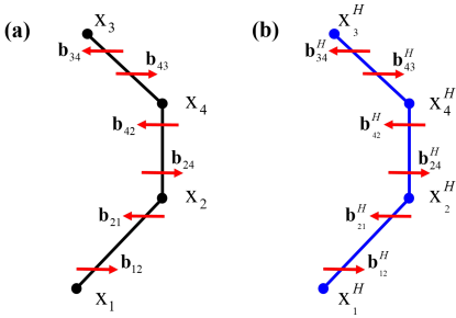
The DDD simulation in this work are nodal based (Bulatov and Cai, 2006; Arsenlis et al., 2007), i.e. dislocations are represented by discrete straight segments as shown in Fig. 1(a), and the dislocation motion is accounted for by evaluating the velocity of node at position through a general linear mobility law which describes the dislocation mobility with various modes such as glide, climb and cross-slip.
In general, the force per unit length on a dislocation line segment bounded by nodes and is
| (1) |
where is the local stress at point on the dislocation line, is the Burgers vector, and is the unit tangent vector of the dislocation line segment. In the DDD simulation, the non-singular continuum theory of dislocations (Cai et al., 2006) is adopted. Using the convention that nodal values are denoted in uppercase, the total nodal force on node , connected to node is evaluated in three parts
| (2) |
where is the elastic force due to segment integrated along segment . This is summed over all segments inside the domain, including the self force due to segment , this is then summed over all nodes which are connected to node . is the corrective elastic force obtained using FEM to account for the applied and image stresses and is the force due to the dislocation core energy.
The PK force due to dislocations arises from the stress fields of straight dislocation segments. Take the configuration in Fig. 1(a) for instance, the stress tensor at a field point induced by the dislocation segment can be expressed as Arsenlis et al. (2007)
| (3) | ||||
where is the shear modulus, the Poisson’s ratio, the core width and the second order identity tensor. , and . The nodal force at node due to the interaction between segment with Burgers vector , and the segment with stress field is
| (4) | ||||
, and . Analytic expressions for Equation 13 have been given by Arsenlis et al. (2007).
2.2 Dislocation mobility law
A linear dislocation mobility law is adopted. For each segment , a drag tensor is determined according to the segment character, the nodal velocity at node is then obtained using
| (5) |
where the sum is again over all nodes connected to node , and is the nodal force determined by Equation 2. To construct drag tensor suitable for bcc materials (Bulatov and Cai, 2006), the cases of pure screw and pure edge components are considered first. A pure screw dislocation segment is assigned with isotropic mobility in all directions perpendicular to its line direction, which mimics the so-called “pencil-glide”
| (6) |
where is a drag coefficient for the motion of screw dislocations and to allow a node to move rapidly along the line direction. Meanwhile, the mobility of a pure edge segment is anisotropic with respect to glide and climb,
| (7) |
where and are the drag coefficients for glide and climb, respectively. The unit vectors are the plane normal and glide direction . To account for the mobility of mixed segments, an interpolation function was proposed by Cai and Bulatov (2004), enabling a smooth transition between the two limits
| (8) | ||||
The dislocation mobility is inversely proportional to the drag coefficient. In bcc materials, the mobility of a pure edge segment should be greater than a pure screw segment, which is accounted for by assigning . Climb is neglected throughout this work by using a . More details regarding the selection of drag coefficients are presented in subsection 3.1. Besides, it should be noted that the “pencil glide”assumption for pure screw mobility is a simplified treatment, however, it is sufficient for the present work where the effect of hydrogen on slip planarity is attributed to its influence on the proportion of near screw segments and this effect will remain qualitatively unchanged with a different cross-slip law.
2.3 Treatment of finite boundary conditions
Dislocations in a finite medium are subjected to the corrective force term which appears on the right hand side of Equation 2. To evaluate the corrective fields the superposition principle (Giessen and Needleman, 1995; Weygand et al., 2002) is adopted. Denoting the infinite-body fields as and the finite-element correction fields with , the total stress, strain and displacement fields are expressed as
| (9) |
respectively. The following procedure (El-Awady et al., 2008) is adopted to evaluate the image stress field. First, the elastic stress field due to dislocations in an infinite body, , is obtained using Equation 3; the tractions on the traction boundaries due to this stress are then calculated, reversed and added to the prescribed traction boundary conditions ; these modified boundary values, , in addition to any prescribed displacement conditions on the displacement boundaries are used in an elastic finite element simulation to determine the corrective fields. Finally, the corrective stress field, , is used to evaluate the corrective nodal force .
2.4 Hydrogen elastic shielding
The hydrogen stress contribution required for three dimensional DDD process was recently obtained by Gu and El-Awady (2018) using isotropic linear elasticity theory, based on the work of Cai et al. (2014). Hydrogen atoms were viewed as point defects of Eshelby type (Eshelby, 1955), and it was assumed that hydrogen diffusion is sufficiently rapid that hydrogen atoms can move with the dislocations. Therefore equilibrium of chemical potential is guaranteed over the domain. This was referred to as the “fast diffusion” scenario which is suitable for bcc materials. Under this assumption, steady-state hydrogen redistribution is established at all times, and is only a function of the dislocation pressure field ,
| (10) |
where is the hydrogen field distribution expressed as the occupancy. Occupancy is related to hydrogen concentration through , where is the maximum concentration or equivalently, the number of atomic sites per unit volume where each site can accomodate one hydrogen atom. The volume expansion of the matrix due to a hydrogen atom is , and is the reference occupancy under a uniform pressure
| (11) |
with being the reference chemical potential of hydrogen in a stress-free infinite medium. In reality, could represent the chemical potential of hydrogen in a remote reservoir and should be viewed as the initial hydrogen potential in the bulk.
The hydrogen population as distributed point defects will generate an elastic stress field which is dependent on the spatial distribution of hydrogen occupancy; which is a function of stress. Therefore the hydrogen induced stress is dependent on the dislocation configuration in the domain, as indicated in Equation 10. According to Gu and El-Awady (2018), the hydrogen stress field in three dimensions can be expressed as
| (12) | ||||
This is proportional to the last three terms (the none screw terms) of the dislocation stress field in Equation 3, indicating that the hydrogen elastic stress field can be evaluated via a similar approach to evaluating the stress generated by a dislocation segment. Following Gu and El-Awady (2018), the hydrogen induced PK force is based on virtual hydrogen-related dislocation segments as illustrated in Fig. 1(b). Due to the fast diffusion assumption for bcc materials, the hydrogen-related dislocation segments are simply the dislocation segments, and the hydrogen induced force at a node at on the dislocation segment arising from the hydrogen stress field is calculated using
| (13) | ||||
and this term needs to be added to the right hand side of Equation 2.
In a finite volume, the hydrogen stress field generates tractions on the surfaces of the body. This will cause the body to deform slightly inducing an additional image stress which will contribute to the force on the dislocation nodes. This corrective stress field which includes the additional hydrogen image stress is obtained using FEM with the modified traction boundary condition . The total elastic fields are then the superposition of the corrective FEM fields, , the analytic dislocation fields and analytic hydrogen fields
| (14) |
After obtaining and consequently , the corrective force which includes the hydrogen image force, the total nodal force on node can be evaluated
| (15) |
where is the elastic force due to the hydrogen segment integrated along segment .
2.5 Hydrogen dependent mobility law
The influence of hydrogen on dislocation mobility can be directly captured by atomistic simulations. Katzarov et al. (2017) calibrated the effect of hydrogen on the mobility of pure screw dislocations in -Fe, using kMC based on first principle calculations (Itakura et al., 2013). A quantitative relationship between dislocation mobility and bulk hydrogen concentration were extracted under different temperatures and applied stresses. This work concerns the ambient temperature case, and the corresponding curves is reproduced with permission from Katzarov et al. (2017) in Fig. 2(a). The hydrogen effects are evaluated under three applied stress levels, and hydrogen enhanced dislocation mobility was observed up to appm in all the cases.
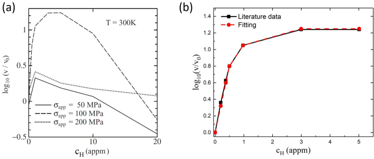
Hydrogen effects on dislocation mobility are incorporated into the DD simulation based on Fig. 2(a). In order to maintain a linear mobility law, the drag coefficients are assumed to be dependent on hydrogen but independent of applied stress. The curve corresponding to MPa is adopted throughout. Further, considering the small bulk hydrogen concentration in bcc materials, only the initial part of the curve appm was fitted. Plotting this part in Fig. 2(b), the following linear fitting was obtained,
| (16) |
According to this equation, the increase in dislocation mobility due to hydrogen can be as large as times with appm. In this work, however, the maximum increase achieved is less than due to the small initial bulk concentration used.
In DD simulations, the local hydrogen concentration at each segment is evaluated during each iteration. The drag coefficient for each segment is scaled using Equation 16 and the nodal velocity is then found using Equation 5. The scalar drag coefficients used to construct the drag tensor Equation 8 for each segment were reduced using
| (17) |
where is the hydrogen free drag coefficient, either or . Note that was unchanged to ensure climb did not occur.
The local hydrogen concentration at a field point is obtained using Equation 10. However, the normal components of the non-singular stress field of a straight dislocation segment are all zero on the dislocation line and so when the field point is on a dislocation segment. Therefore, in order to evaluate the concentration on a dislocation segment without neglecting the self stress of the segment, the concentration was found at 2 field points at , either side of the segment midpoint, and then averaged. Where is the core width in Equation 3 and the glide plane normal of the segment.
The kMC investigation into hydrogen effects on screw mobility in Katzarov et al. (2017) was performed considering hydrogen concentration near the dislocation core which was well captured by first principle calculations (Itakura et al., 2013). Starting from a sensible bulk hydrogen concentration, e.g. appm a very high hydrogen occupancy up to (equivalent to ) could build up in the core region due to its high binding energy. Such a high concentration is impossible to achieve within linear elasticity theory. This implies the hydrogen increased dislocation mobility could be viewed as the total effect including the contribution of hydrogen in the core region, whereas hydrogen elastic shielding considers only the weak hydrogen accumulation generated by the remote dislocation elastic stress fields. The local hydrogen concentration obtained in the current DDD simulation should be considered equivalent to the bulk concentration (Katzarov et al., 2017) instead of the equilibrium concentration at binding sites in atomic simulations.
Exactly how hydrogen influences edge mobility is unclear, since no quantitative description is available and there is consensus in the literature. Robertson (2001) concluded that hydrogen increases dislocation mobility equally for edge and screw dislocations, while atomistic simulations predict hydrogen reduces edge mobility (Song and Curtin, 2014; Bhatia et al., 2014) and increases screw mobility (Itakura et al., 2013; Katzarov et al., 2017). Experimentally, Xie et al. (2016) observed hydrogen decreased edge dislocation mobility in Al during in situ micropillar cyclic loading test, and the same author (Xie, 25 May 2018) most recently observed hydrogen enhanced screw mobility in Fe using similar technique. Therefore we tested two cases. Case assumes hydrogen only increases screw mobility, and case assumes an equal influence on screw and edge mobility
| (18) | ||||
with defined in Equation 17 where the concentration field varies in space and is evaluated at the segment midpoint. For cases , it is noted that screw segments still possess lower mobility than edge segments in the presence of hydrogen in all simulations as .
3 Hydrogen effects in an infinite medium
3.1 Geometry for hydrogen informed DDD simulation
With hydrogen informed DDD simulation, the influence of hydrogen on dislocation generation, pile-up and slip planarity is investigated starting from a FR source in an infinite solid subjected to both zero and non-zero out-of-plane PK forces. The findings here will provide rationalization for the phenomena observed in microcantilever bending simulations in section 4. In all the simulations, two different hydrogen effects, hydrogen elastic shielding and hydrogen increased dislocation mobility, are considered and their contributions evaluated. Subsequently, the model geometry and loading conditions are introduced first, and the selection of model parameters is then elaborated.
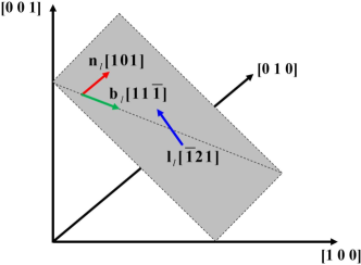
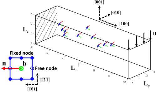
A pure edge dislocation belonging to the slip system is selected as the initial configuration for DDD simulation in an infinite medium. The dislocation lies on the plane and is pinned at both ends, as shown in Fig. 3. Its behavior is dependent on the applied stress in the local coordinate system. For easier illustration, the model is rotated into a global system, with axis along , and , as shown in Fig. 4 and Fig. 5. The stress tensors in the global coordinate system are readily obtained
| (19) |
where is the rotation matrix from the local (crystal) to the global (dislocation) frame
| (20) |
In Fig. 4, out-of-plane pure shear is applied
| (21) |
The PK forces on all dislocation components are in plane, therefore, the initial edge dislocation behaves as an FR source.
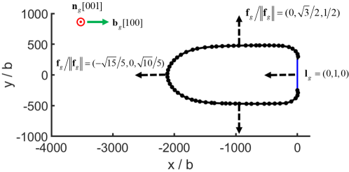
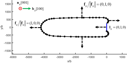
In Fig. 5, uniaxial tension along the crystallographic direction in the local coordinate system is applied, which in the global system is expressed as
| (22) |
At the beginning, the pure edge dislocation bows out to the left driven by the PK force with a component in the negative x direction. Although this PK force possesses a non-zero component in the positive z direction, it does not cause any out-of-plane motion of the edge segment, since climb is not permitted. During the bowing out, pure screw segments are generated, which move in the y direction and cross slip. Therefore, when the dislocation bows back, the screw segments are unable to annihilate each other unless they first cross slip back onto the same plane. The simple model illustrated in Fig. 4 is used to investigate hydrogen effects on dislocation generation and pile-up, and that in Fig. 5 is used to study hydrogen effects on slip planarity, with the results elaborated in subsection 3.2 and subsection 3.3, respectively.
Adopting the material parameters (relevant to Ni), initial loop size and hydrogen concentration values used by Gu and El-Awady (2018), the same results in terms of PK force magnitude and loop shape change were obtained, which are not repeated here. With the current implementation validated, material parameters relevant to Fe, were used to simulate an FR source. The Burgers vector magnitude is , where Å is the lattice parameter; isotropic linear elasticity is assumed, with a shear modulus GPa and Poisson’s ratio (Tang and Marian, 2014). In the absence of hydrogen, the edge and screw drag coefficients are and as used by Wang and Beyerlein (2011). Climb is disabled in the current work, therefore, only pure screw segments can possibly move out of the glide plane, and a dislocation segment is considered pure screw if the angle between its line direction and Burgers vector is . The dislocation core width is selected as , as used by Arsenlis et al. (2007) and Ayas et al. (2014). For DDD simulation in an infinite medium (Fig. 4 and Fig. 5), the initial dislocation length is in both cases. The applied shear stress in Equation 21 is MPa, and the uniaxial tension stress is MPa in Equation 22. All simulations are for K, and the fast diffusion scenario (Gu and El-Awady, 2018) is assumed, given the large diffusivity of hydrogen in bcc materials at this temperature. As for the initial bulk hydrogen concentration, an extremely large value appm is selected to produce a noticeable effect with only hydrogen elastic shielding taken into account; a realistic value appm is then adopted in the simulations considering hydrogen increased dislocation mobility.
3.2 A Frank-Read source in the presence of hydrogen
3.2.1 Hydrogen elastic shielding
For Fe, the maximum hydrogen concentration in Equation 10 is lower than Ni. The lower mobility of screw components in Fe results in an elongated dislocation loop, as shown in Fig. 6, instead of a circular one in Ni. As the density of screw segments (which have no elastic interaction with hydrogen) is higher in Fe than in Ni the effect of hydrogen shielding is reduced for the same occupancy. Therefore, a higher hydrogen occupancy was required than by Gu and El-Awady (2018), in order to produce noticeable hydrogen influence.
Starting from an extremely high bulk concentration appm, hydrogen elastic shielding influences the behavior of a FR source, as shown in Fig. 6. With hydrogen present the dislocation loops generated by the FR source move further, and one extra dislocation loop is generated, indicating that hydrogen shielding can promote dislocation nucleation. In addition, the average spacing between the dislocation loops is slightly decreased due to hydrogen, as also observed by Gu and El-Awady (2018).
The nodal force contribution due to the dislocation segments and the uniform applied stress and due to the hydrogen stress (scaled ) are plotted shortly after the first bow out of the FR source in Fig. 7(a). The direction of tends to expand the half loop and cause it to pinch off to generate a full loop. The distribution of is highly dependent on the character of the segments connected to the node. In general, the values are always much less than the other elastic forces and are largest on the nodes connected to edge dominated segments. on nodes on long screw segments are negligible. This is expected as screw dislocations exert zero hydrostatic stress there is no elastic interaction with the hydrogen, e.g. using Equation 12 shows for a pure screw segment. The hydrogen force, , along pure edge segments or mixed segments which are edge dominant opposes the other elastic forces, , whereas the directions are the same for mixed segments which are screw dominant, as shown in Fig. 7(b). This indicates that hydrogen has a tendency to slow down the loop expansion along . As the anisotropy in the mobility is slightly reduced, this leads to a slightly more circular shape of the half loop. In addition, Fig. 7(c) shows how the hydrogen force promotes the attraction of the short screw dominant segments. Making it easier for the segments to bow back and pinch off to nucleate a loop.
So far, hydrogen elastic shielding has been demonstrated to have a tendency to enhance dislocation nucleation and to decrease the average spacing. However, it should be noted that to achieve this required an extremely high bulk hydrogen concentration, e.g. appm. With realistic bulk concentrations for bcc Fe, the elastic hydrogen effect becomes negligible. This was verified using appm. In this case, the FR source behaviour was identical to the hydrogen-free case in Fig. 6 and so is not repeated.
3.2.2 Hydrogen increased mobility
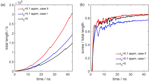
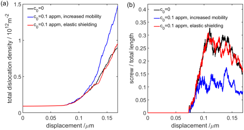
We now consider the effect of hydrogen increased mobility at a realistic bulk concentration of appm. Both case and case , as outlined in Equation 18, are investigated. The dislocation structures with and without hydrogen after the same simulated time are superimposed in Fig. 8.
In both cases, more loops are generated, in the presence of hydrogen. The total dislocation line length increases with the hydrogen enhanced mobility as shown in Fig. 9(a). In case , where hydrogen only enhances screw mobility, the shape of the loop differs from the hydrogen free situation. Whereas in case , where hydrogen exerts equal influence on both screw and edge mobilities, the shape of the loops is unchanged. Fig. 9(b) shows how the proportion of screw dominant segments evolves with simulated time. Here, a segment is considered screw dominant if the angle between and is less than . It is noted this criterion is only used during postprocessing to identify screw like segments. The proportion of screw like segments is reduced in case but unchanged in case . This same trend can also be reproduced be ignoring the spatial distribution of hydrogen completely and uniformly increasing the screw mobility (a simplified case I) or uniformly increasing the mobility of all segments (a simplifed case II). The same dislocation structure is predicted in case II as without hydrogen, but at an earlier simulated time.
In case , hydrogen promotes dislocation generation via increased screw mobility and the shape of loops becomes more circular; in case , hydrogen accelerates dislocation evolution but has little influence on the final dislocation structure in quasi static loading. Case reduces the anisotropy in the dislocation motion, this was noted by Bhatia et al. (2014) and observed experimentally in Moriya et al. (1979). Case , however, finds no direct evidence in the literature except for a very general statement in Robertson (2001), besides, case II implies hydrogen does not alter the dislocation structure. This is inconsistent with experimental evidence on hydrogen enhanced plasticity. Therefore only case , i.e. hydrogen increases screw mobility, is used in the following sections.
3.3 Hydrogen effects on slip planarity
3.3.1 Hydrogen elastic shielding
Ferreira et al. (1999) attempted to explain hydrogen enhanced slip planarity in terms of hydrogen elastic shielding, as reviewed in subsection 1.2. From the energetic point of view, it was shown with linear elasticity theory that hydrogen elastic forces reduced the energy of edge dislocations relative to screw thereby reducing the frequency of cross-slip. It should be noted that this mechanism only occurred at a high concentration, appm. Following this idea, we first investigate the role of hydrogen elastic shielding in enhanced slip planarity.
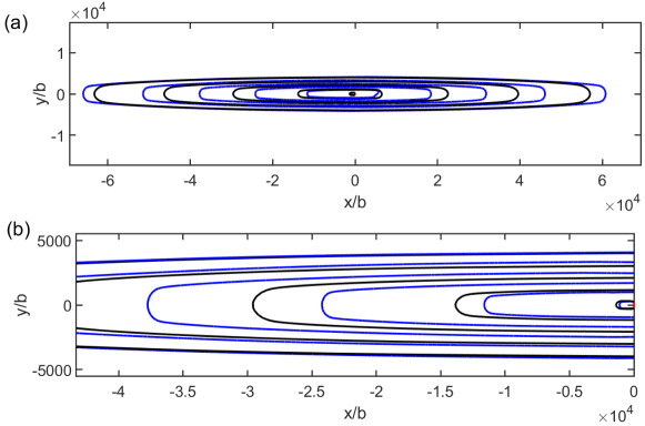
The applied stress was chosen to generate an out-of-plane PK force so that screw segments cross slip. Similar to the case in subsubsection 3.2.1, an extremely high bulk concentration appm was used. The dislocation structures with and without hydrogen are superimposed in Fig. 10, and it is clear that out of plane motion is suppressed in the presence of hydrogen.
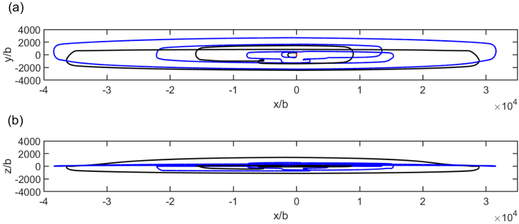
During each iteration, all segments are checked, and a segment is considered out-of-plane if both its nodes are, . The total dislocation line length and the proportion which is out of plane are both reduced by the hydrogen elastic force. The onset of cross slip is also delayed as shown in figure Fig. 11
The nodal force on screw like segments is shown in Fig. 12.
For nodes on the slip plane, and act in the same direction, driving the screw like segments apart but in opposition on the edge segments. but still sufficient to decrease the anisotropy in the loop expansion, decreasing the screw length and hence the amount of cross-slip. This is consistent with the theory in Ferreira et al. (1999) that hydrogen tends to reduce the pure screw population. has a small out of plane component but is predominantly in plane. Furthermore is entirely in plane prior to the initial out-of-plane motion which delays the first cross slip event. The hydrogen elastic force is only noticeable at extremely high bulk concentrations, and so can be neglected for bcc Fe.
3.3.2 Hydrogen increased mobility
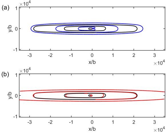
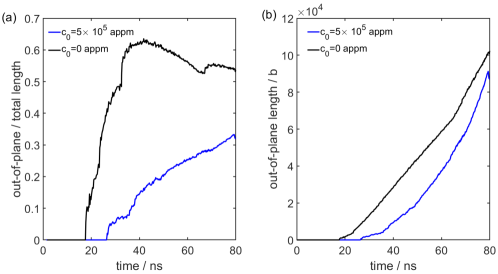
The cross slip simulations were repeated with a hydrogen enhanced screw mobility law (case I) and a bulk concentration of appm. Time histories of the proportion of out-of-plane dislocation length are plotted in Fig. 13(a).
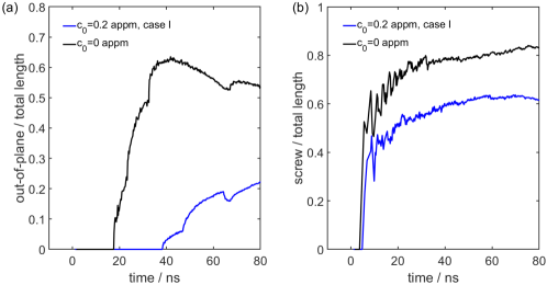
The out-of-plane dislocation motion is delayed and suppressed in the presence of hydrogen. It is therfore hypothesised that hydrogen enhanced slip planarity is due to the hydrogen induced shape change of dislocation loops. The evolution of the proportion of screw like segments is shown in Fig. 13(b), which decreases in the presence of hydrogen. Indicating that hydrogen enhances slip planarity by reducing the amount of cross slip as the proportion of pure screw segments is reduced.
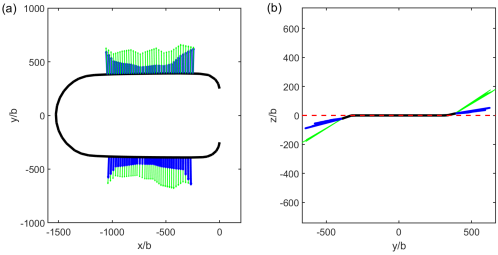
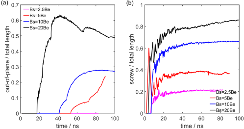
To provide further support for this hypothesis, three simplified simulations with, , , and and no hydrogen, , were performed. These ideal cases, shown in Fig. 14 qualitatively resemble the hydrogen enhanced screw mobility, Fig. 13, and are free of the complexity associated with the hydrogen distribution.
Hydrogen can therefore enhance slip planarity through hydrogen enhanced screw mobility at a realistic bulk concentration appm for bcc Fe, in contrast to the extremely high value of appm required for the hydrogen elastic force. Finally, it should be reemphasized that out-of-plane dislocation motions in this work are due to cross slip of pure screw segments, and climb is considered. The influence of hydrogen on climb will add further complexity.
4 Hydrogen effects in a microcantilever
In situ hydrogen charged microcantilever bend tests on single crystal Fe- Si alloy and single crystal FeAl alloy were recently performed by Hajilou et al. (2017) and Deng and Barnoush (2018), respectively. Here we simulate a microcantilever with dimension and to investigation hydrogen effects in a finite volume. The crystal orientation is aligned with the axis along the model axis as shown in Fig. 15; the same orientation used in the experiments by Deng and Barnoush (2018). However we do not attempt to reproduce the exact experimental data at the present stage, since the microcantilever geometry simulated here is simplified, with a square cross section and without a base or notch. For simplicity only the slip system is included in the simulation. The sources were square prismatic loops with eight nodes, of which were fixed, as shown in Fig. 15. A total of 10 sources were used. The boundary conditions were: , with an applied displacement of and the remaining surfaces were traction free. Fully integrated linear brick finite elements, in size, were used to solve for the corrective elastic fields at every time increment.
Hydrogen elastic shielding and hydrogen enhanced screw mobility are considered with a realistic initial bulk hydrogen concentration for bcc Fe, appm. The sources are subjected to an approximately uniaxial stress, , which is tensile above and compressive below the neutral plane located at . The initial stress state is therefore similar to the slip planarity investigation in an infinite volume discussed in subsection 3.3.
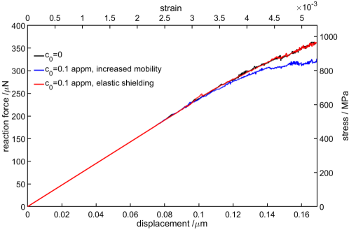
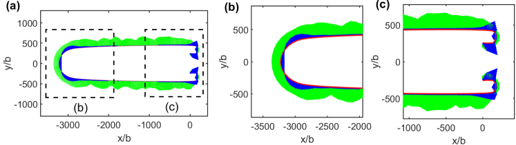
The load displacement curve is shown in Fig. 16 which shows a clear softening effect through the hydrogen enhanced screw mobility law and no noticeable effect through hydrogen elastic shielding; consistent with the infinite volume simulations. The hydrogen softening can be rationalised by analyses of the dislocation structure, which is shown in Fig. 17.
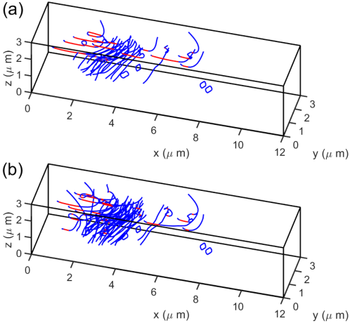
In both cases, dislocation pile-ups form at the the neutral plane. However, the number of dislocations in a pile up is higher when hydrogen is included, and the proportion of screw like segments is reduced, as shown in Fig. 18. It is therefore concluded that hydrogen enhances dislocation activity in bcc Fe and consequently leads to global softening behavior, which is consistent with the HELP mechanism and agrees with the observation of hydrogen reducing the yield stress in microcantilever experiments (Hajilou et al., 2017; Deng and Barnoush, 2018). Our simulations indicate the effect is due to hydrogen increased screw mobility, and the contribution of hydrogen elastic shielding is negligible. Further, Fig. 18(b) suggests that hydrogen enhances slip planarity due to a reduction in the proportion of screw segments available to cross slip. The simulated dislocation density increases in the presence of hydrogen, this is in contrast to the expectation in some literature (Nibur et al., 2006) that enhanced planarity would lead to hardening. This could be because only one slip system was simulated and so junction formation was not considered. Or it could be due to the existence of a neutral plane which arrests a large number of dislocations. Multiple slip systems and an additional geometry, e.g. micropillar, with a uniform stress state will be simulated in future work to provide further insight.
The component of the dislocation stress, , and the total stress, , along the beam axis, with and without hydrogen enhanced screw mobility are shown in Fig. 19.
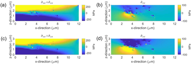
The stress hot spot is due to the pile up of edge dislocations at the neutral plane, and is more pronounced with hydrogen due to the higher dislocation density. As the dislocation field is compressive above the neutral plane and compressive below, the overall stress and reaction force is reduced more when hydrogen is present.
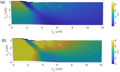
The dislocation displacement field, , is shown in figure Fig. 20. When a dislocation segment leaves the material at a free surface it generates a plastic slip step. Hydrogen promotes plastic deformation, and the number of internal and exited segments increases, which increases the magnitude of the field and the slip step height respectively.
5 Conclusions
In this paper, the formulation proposed by Gu and El-Awady (2018) to incorporate the hydrogen elastic force was implemented in DDD to simulate a Frank-Read source and within DDP to simulate a microcantilever. A hydrogen enhanced mobility law for screw dislocations was also implemented; based on hydrogen-kink pair interactions simulated by Katzarov et al. (2017) using kMC.
Hydrogen elastic shielding was found to have a tendency to promote dislocation generation, decrease dislocation spacing and enhance slip planarity. The elastic hydrogen force accelerates the bowing back and annihilation of screw dipoles in FR sources reduces the proportion of screw segments, which limits cross slip. These results are consistent with the HELP mechanism (Birnbaum and Sofronis, 1994; Ferreira et al., 1999). However our simulations demonstrated that this only occurs with an nonphysically high bulk hydrogen concentration, e.g. appm in Gu and El-Awady (2018) and appm in this work, which is unrealistic for bcc metals. In contrast, a significant hydrogen influence on dislocation activity was observed by implementing a hydrogen concentration dependent mobility law for the screw component of dislocation segments. At realistic bulk hydrogen concentrations appm and appm hydrogen was found to promotes dislocation generation and enhances slip planarity. Hydrogen reduces the anisotropy in the mobility resulting in more circular loops (Bhatia et al., 2014; Moriya et al., 1979), and this also tends to reduce the screw population, making the bowing back of FR sources easier and reducing cross slip.
Both hydrogen elastic shielding and hydrogen increased screw mobility tend to enhance dislocation activity, and the mechanisms of the enhancement are actually quite similar. Therefore, hydrogen increased mobility should be viewed as a complementary explanation for the HELP mechanism, and it contributes a larger part than hydrogen (linear) elastic shielding, since it essentially arises from hydrogen-kink pair interactions close to the dislocation core, where very high stress and hydrogen concentrations exist but cannot be captured by linear elasticity theory.
Microcantilever simulations with a hydrogen dependent mobility law showed more pronounced dislocation pile-ups form at the neutral plane, and a reduction in the flow stress. Finally, it should be noted again that dislocation climb was excluded in all the simulations, therefore, hydrogen enhanced slip planarity is a consequence only of hydrogen affected cross slipping in the present work.
Acknowledgements
This work was supported by the Engineering and Physical Sciences Research Council (Programme grant EP/L014742/1 and Fellowship grant EP/N007239/1). We also thank Prof. El-Awady for a useful discussion at the 3rd Schöental Symposium on Dislocation based Plasticity.
References
References
- Gu and El-Awady (2018) Y. Gu, J. A. El-Awady, Quantifying the effect of hydrogen on dislocation dynamics: A three-dimensional discrete dislocation dynamics framework, Journal of the Mechanics and Physics of Solids.
- Katzarov et al. (2017) I. H. Katzarov, D. L. Pashov, A. T. Paxton, Hydrogen embrittlement i. analysis of hydrogen-enhanced localized plasticity: Effect of hydrogen on the velocity of screw dislocations in -fe, Physical Review Materials 1 (3) (2017) 033602, pRMATERIALS.
- Ayas et al. (2014) C. Ayas, J. A. W. van Dommelen, V. S. Deshpande, Climb-enabled discrete dislocation plasticity, Journal of the Mechanics and Physics of Solids 62 (2014) 113–136.
- Robertson et al. (2015) I. Robertson, P. Sofronis, A. Nagao, M. L. Martin, S. Wang, D. W. Gross, K. E. Nygren, Hydrogen embrittlement understood, Metallurgical and Materials Transactions B 46 (3) (2015) 1085–1103.
- Oriani (1972) R. A. Oriani, A mechanistic theory of hydrogen embrittlement of steels, Berichte der Bunsengesellschaft für physikalische Chemie 76 (8) (1972) 848–857.
- Lynch (2012) S. Lynch, Hydrogen embrittlement phenomena and mechanisms, Corrosion Reviews 30 (3-4) (2012) 105.
- Birnbaum and Sofronis (1994) H. K. Birnbaum, P. Sofronis, Hydrogen-enhanced localized plasticity—a mechanism for hydrogen-related fracture, Materials Science and Engineering: A 176 (1) (1994) 191–202.
- Robertson (2001) I. M. Robertson, The effect of hydrogen on dislocation dynamics, Engineering Fracture Mechanics 68 (6) (2001) 671–692.
- Novak et al. (2010) P. Novak, R. Yuan, B. P. Somerday, P. Sofronis, R. O. Ritchie, A statistical, physical-based, micro-mechanical model of hydrogen-induced intergranular fracture in steel, Journal of the Mechanics and Physics of Solids 58 (2) (2010) 206–226.
- Barrera et al. (2014) O. Barrera, E. Tarleton, A. Cocks, A micromechanical image-based model for the featureless zone of a Fe–Ni dissimilar weld, Philosophical Magazine 94 (12) (2014) 1361–1377.
- Nagao et al. (2018) A. Nagao, M. Dadfarnia, B. P. Somerday, P. Sofronis, R. O. Ritchie, Hydrogen-enhanced-plasticity mediated decohesion for hydrogen-induced intergranular and “quasi-cleavage” fracture of lath martensitic steels, Journal of the Mechanics and Physics of Solids 112 (2018) 403–430.
- Nagao et al. (2012) A. Nagao, C. D. Smith, M. Dadfarnia, P. Sofronis, I. M. Robertson, The role of hydrogen in hydrogen embrittlement fracture of lath martensitic steel, Acta Materialia 60 (13–14) (2012) 5182–5189.
- Ferreira et al. (1998) P. J. Ferreira, I. M. Robertson, H. K. Birnbaum, Hydrogen effects on the interaction between dislocations, Acta Materialia 46 (5) (1998) 1749–1757.
- Shih et al. (1988) D. S. Shih, I. M. Robertson, H. K. Birnbaum, Hydrogen embrittlement of titanium: In situ tem studies, Acta Metallurgica 36 (1) (1988) 111–124.
- Tabata and Birnbaum (1983) T. Tabata, H. Birnbaum, Direct observations of the effect of hydrogen on the behavior of dislocations in iron, Scripta Metallurgica 17 (7) (1983) 947–950.
- Robertson and Birnbaum (1986) I. M. Robertson, H. K. Birnbaum, An hvem study of hydrogen effects on the deformation and fracture of nickel, Acta Metallurgica 34 (3) (1986) 353–366.
- Bond et al. (1988) G. M. Bond, I. M. Robertson, H. K. Birnbaum, Effects of hydrogen on deformation and fracture processes in high-purity aluminium, Acta Metallurgica 36 (8) (1988) 2193–2197.
- Rozenak et al. (1990) P. Rozenak, I. M. Robertson, H. K. Birnbaum, Hvem studies of the effects of hydrogen on the deformation and fracture of aisi type 316 austenitic stainless steel, Acta Metallurgica et Materialia 38 (11) (1990) 2031–2040.
- Bond et al. (1989) G. M. Bond, I. M. Robertson, H. K. Birnbaum, On the mechanisms of hydrogen embrittlement of ni3al alloys, Acta Metallurgica 37 (5) (1989) 1407–1413.
- Ferreira et al. (1999) P. J. Ferreira, I. M. Robertson, H. K. Birnbaum, Hydrogen effects on the character of dislocations in high-purity aluminum, Acta Materialia 47 (10) (1999) 2991–2998.
- Nibur et al. (2006) K. A. Nibur, D. F. Bahr, B. P. Somerday, Hydrogen effects on dislocation activity in austenitic stainless steel, Acta Materialia 54 (10) (2006) 2677–2684.
- Barnoush and Vehoff (2010) A. Barnoush, H. Vehoff, Recent developments in the study of hydrogen embrittlement: Hydrogen effect on dislocation nucleation, Acta Materialia 58 (16) (2010) 5274–5285.
- Hajilou et al. (2017) T. Hajilou, Y. Deng, B. R. Rogne, N. Kheradmand, A. Barnoush, In situ electrochemical microcantilever bending test: A new insight into hydrogen enhanced cracking, Scripta Materialia 132 (2017) 17–21.
- Deng et al. (2017) Y. Deng, T. Hajilou, D. Wan, N. Kheradmand, A. Barnoush, In-situ micro-cantilever bending test in environmental scanning electron microscope: Real time observation of hydrogen enhanced cracking, Scripta Materialia 127 (2017) 19–23.
- Deng and Barnoush (2018) Y. Deng, A. Barnoush, Hydrogen embrittlement revealed via novel in situ fracture experiments using notched micro-cantilever specimens, Acta Materialia 142 (2018) 236–247.
- Ulmer and Altstetter (1991) D. G. Ulmer, C. J. Altstetter, Hydrogen-induced strain localization and failure of austenitic stainless steels at high hydrogen concentrations, Acta Metallurgica et Materialia 39 (6) (1991) 1237–1248.
- Matsuo et al. (2014) T. Matsuo, J. Yamabe, S. Matsuoka, Effects of hydrogen on tensile properties and fracture surface morphologies of type 316l stainless steel, International Journal of Hydrogen Energy 39 (7) (2014) 3542–3551.
- Jagodzinski et al. (2000) Y. Jagodzinski, H. Hänninen, O. Tarasenko, S. Smuk, Interaction of hydrogen with dislocation pile-ups and hydrogen induced softening of pure iron, Scripta Materialia 43 (3) (2000) 245–251.
- Wen et al. (2003) M. Wen, S. Fukuyama, K. Yokogawa, Atomistic simulations of effect of hydrogen on kink-pair energetics of screw dislocations in bcc iron, Acta Materialia 51 (6) (2003) 1767–1773.
- Teus et al. (2007) S. M. Teus, V. N. Shivanyuk, B. D. Shanina, V. G. Gavriljuk, Effect of hydrogen on electronic structure of fcc iron in relation to hydrogen embrittlement of austenitic steels, physica status solidi (a) 204 (12) (2007) 4249–4258.
- Taketomi et al. (2008) S. Taketomi, R. Matsumoto, N. Miyazaki, Atomistic simulation of the effects of hydrogen on the mobility of edge dislocation in alpha iron, Journal of Materials Science 43 (3) (2008) 1166–1169.
- Gavriljuk et al. (2010) V. G. Gavriljuk, B. D. Shanina, V. N. Shyvanyuk, S. M. Teus, Electronic effect on hydrogen brittleness of austenitic steels, Journal of Applied Physics 108 (8) (2010) 083723.
- Song and Curtin (2011) J. Song, W. A. Curtin, A nanoscale mechanism of hydrogen embrittlement in metals, Acta Materialia 59 (4) (2011) 1557–1569.
- Song and Curtin (2013) J. Song, W. Curtin, Atomic mechanism and prediction of hydrogen embrittlement in iron, Nature materials 12 (2) (2013) 145.
- Song and Curtin (2014) J. Song, W. A. Curtin, Mechanisms of hydrogen-enhanced localized plasticity: An atomistic study using -fe as a model system, Acta Materialia 68 (2014) 61–69.
- Bhatia et al. (2014) M. A. Bhatia, S. Groh, K. N. Solanki, Atomic-scale investigation of point defects and hydrogen-solute atmospheres on the edge dislocation mobility in alpha iron, Journal of Applied Physics 116 (6) (2014) 064302.
- Anderson et al. (2017) P. Anderson, J. Hirth, J. Lothe, Theory of Dislocations, Cambridge University Press, 2017.
- Itakura et al. (2013) M. Itakura, H. Kaburaki, M. Yamaguchi, T. Okita, The effect of hydrogen atoms on the screw dislocation mobility in bcc iron: A first-principles study, Acta Materialia 61 (18) (2013) 6857–6867.
- Zhao and Lu (2011) Y. Zhao, G. Lu, Qm/mm study of dislocation-hydrogen/helium interactions in -fe, Modelling and Simulation in Materials Science and Engineering 19 (6) (2011) 065004.
- Moriya et al. (1979) S. Moriya, H. Matsui, H. Kimura, The effect of hydrogen on the mechanical properties of high purity iron ii. effect of quenched-in hydrogen below room temperature, Materials Science and Engineering 40 (2) (1979) 217–225.
- Sofronis et al. (2001) P. Sofronis, Y. Liang, N. Aravas, Hydrogen induced shear localization of the plastic flow in metals and alloys, European Journal of Mechanics - A/Solids 20 (6) (2001) 857–872.
- Liang et al. (2003) Y. Liang, P. Sofronis, N. Aravas, On the effect of hydrogen on plastic instabilities in metals, Acta Materialia 51 (9) (2003) 2717–2730.
- Ahn et al. (2007) D. C. Ahn, P. Sofronis, R. H. Dodds Jr, On hydrogen-induced plastic flow localization during void growth and coalescence, International Journal of Hydrogen Energy 32 (16) (2007) 3734–3742.
- Barrera et al. (2016) O. Barrera, E. Tarleton, H. W. Tang, A. C. F. Cocks, Modelling the coupling between hydrogen diffusion and the mechanical behaviour of metals, Computational Materials Science 122 (2016) 219–228.
- Yu et al. (2018) H. Yu, J. S. Olsen, J. He, Z. Zhang, Hydrogen-microvoid interactions at continuum scale, International Journal of Hydrogen Energy.
- Capolungo (2011) L. Capolungo, Dislocation junction formation and strength in magnesium, Acta Materialia 59 (8) (2011) 2909–2917.
- Wu et al. (2013) C. C. Wu, P. W. Chung, S. Aubry, L. B. Munday, A. Arsenlis, The strength of binary junctions in hexagonal close-packed crystals, Acta Materialia 61 (9) (2013) 3422–3431.
- Arsenlis et al. (2007) A. Arsenlis, W. Cai, M. Tang, M. Rhee, T. Oppelstrup, G. Hommes, T. G. Pierce, V. V. Bulatov, Enabling strain hardening simulations with dislocation dynamics, Modelling and Simulation in Materials Science and Engineering 15 (6) (2007) 553.
- Fitzgerald et al. (2012) S. P. Fitzgerald, S. Aubry, S. L. Dudarev, W. Cai, Dislocation dynamics simulation of frank-read sources in anisotropic -fe, Modelling and Simulation in Materials Science and Engineering 20 (4) (2012) 045022.
- Aubry et al. (2011) S. Aubry, S. P. Fitzgerald, S. L. Dudarev, W. Cai, Equilibrium shape of dislocation shear loops in anisotropic -fe, Modelling and Simulation in Materials Science and Engineering 19 (6) (2011) 065006.
- Motz et al. (2008) C. Motz, D. Weygand, J. Senger, P. Gumbsch, Micro-bending tests: A comparison between three-dimensional discrete dislocation dynamics simulations and experiments, Acta Materialia 56 (9) (2008) 1942–1955.
- Motz et al. (2009) C. Motz, D. Weygand, J. Senger, P. Gumbsch, Initial dislocation structures in 3-d discrete dislocation dynamics and their influence on microscale plasticity, Acta Materialia 57 (6) (2009) 1744–1754.
- Ryu et al. (2013) I. Ryu, W. D. Nix, W. Cai, Plasticity of bcc micropillars controlled by competition between dislocation multiplication and depletion, Acta Materialia 61 (9) (2013) 3233–3241.
- Po et al. (2016) G. Po, Y. Cui, D. Rivera, D. Cereceda, T. D. Swinburne, J. Marian, N. Ghoniem, A phenomenological dislocation mobility law for bcc metals, Acta Materialia 119 (2016) 123–135.
- Cui et al. (2016) Y. Cui, G. Po, N. Ghoniem, Temperature insensitivity of the flow stress in body-centered cubic micropillar crystals, Acta Materialia 108 (2016) 128–137.
- Cui et al. (2017) Y. Cui, G. Po, N. Ghoniem, Does irradiation enhance or inhibit strain bursts at the submicron scale?, Acta Materialia 132 (2017) 285–297.
- Cai et al. (2014) W. Cai, R. B. Sills, D. M. Barnett, W. D. Nix, Modeling a distribution of point defects as misfitting inclusions in stressed solids, Journal of the Mechanics and Physics of Solids 66 (2014) 154–171.
- Giessen and Needleman (1999) E. V. D. Giessen, a. Needleman, Discrete dislocation plasticity: a simple planar model, Modelling and Simulation in Materials Science and Engineering 3 (1999) 689–735.
- El-Awady et al. (2008) J. A. El-Awady, S. Bulent Biner, N. M. Ghoniem, A self-consistent boundary element, parametric dislocation dynamics formulation of plastic flow in finite volumes, Journal of the Mechanics and Physics of Solids 56 (5) (2008) 2019–2035.
- Bulatov and Cai (2006) V. Bulatov, W. Cai, Computer simulations of dislocations, Vol. 3, Oxford University Press on Demand, 2006.
- Cai et al. (2006) W. Cai, A. Arsenlis, C. R. Weinberger, V. V. Bulatov, A non-singular continuum theory of dislocations, Journal of the Mechanics and Physics of Solids 54 (3) (2006) 561–587.
- Cai and Bulatov (2004) W. Cai, V. V. Bulatov, Mobility laws in dislocation dynamics simulations, Materials Science and Engineering: A 387-389 (2004) 277–281.
- Giessen and Needleman (1995) E. V. d. Giessen, A. Needleman, Discrete dislocation plasticity: a simple planar model, Modelling and Simulation in Materials Science and Engineering 3 (5) (1995) 689.
- Weygand et al. (2002) D. Weygand, L. H. Friedman, E. V. d. Giessen, A. Needleman, Aspects of boundary-value problem solutions with three-dimensional dislocation dynamics, Modelling and Simulation in Materials Science and Engineering 10 (4) (2002) 437.
- Eshelby (1955) J. D. Eshelby, The elastic interaction of point defects, Acta Metallurgica 3 (5) (1955) 487–490.
- Xie et al. (2016) D. Xie, S. Li, M. Li, Z. Wang, P. Gumbsch, J. Sun, E. Ma, J. Li, Z. Shan, Hydrogenated vacancies lock dislocations in aluminium, Nature communications 7 (2016) 13341.
- Xie (25 May 2018) D. Xie, Personal communication, 25 May 2018.
- Tang and Marian (2014) M. Tang, J. Marian, Temperature and high strain rate dependence of tensile deformation behavior in single-crystal iron from dislocation dynamics simulations, Acta Materialia 70 (2014) 123–129.
- Wang and Beyerlein (2011) Z. Q. Wang, I. J. Beyerlein, An atomistically-informed dislocation dynamics model for the plastic anisotropy and tension–compression asymmetry of bcc metals, International Journal of Plasticity 27 (10) (2011) 1471–1484.