Design of the MagAO-X Pyramid Wavefront Sensor
1 Abstract
Adaptive optics systems correct atmospheric turbulence in real time. Most adaptive optics systems used routinely correct in the near infrared, at wavelengths greater than 1 m. MagAO-X is a new extreme adaptive optics (ExAO) instrument that will offer corrections at visible-to-near-IR wavelengths. MagAO-X will achieve Strehl ratios of 70 at H when running the 2040 actuator deformable mirror at 3.6 . A visible pyramid wavefront sensor (PWFS) optimized for sensing at 600-1000 wavelengths will provide the high-order wavefront sensing on MagAO-X. We present the optical design and predicted performance of the MagAO-X pyramid wavefront sensor. [1]
2 Introduction
MagAO-X is a new visible-to-near-IR extreme adaptive optics system (ExAO) for the 6.5 Magellan Clay telescope. Working off of lessons learned from MagAO [2] (P.I. Laird Close), and SCExAO [3] (P.I. Olivier Guyon), MagAO-X is optimized for high impact science cases, such as a survey of nearby newly formed accreting planets in H. [1]. To achieve excellent contrast and resolution. MagAO-X will utilize a 2040 actuator deformable mirror (DM) in conjunction with a cutting-edge coronagraph for starlight suppression. A pyramid wavefront sensor (PWFS) will provide high order wavefront sensing. In this paper we present the design and predicted performance of the MagAO-X pyramid wavefront sensor. For a general overview of the MagAO-X instrument see Males et al. 2018 [4], and for the optomechanical design see Close et al. 2018 [5].
The pyramid wavefront sensor (1996 by Ragazzoni) [6] is a pupil plane wavefront sensor that in effect works as a 2-D Foucault knife-edge test. In commonly used configurations, the focal plane is split into four quadrants using a double achromatic prism, (LBTAO, and MagAO), or using two roof prisms, (SCExAO). Each quadrant of the focal plane is then reimaged, producing four separate pupil images on the detector. Local wavefront slopes are calculated using the quad-cell centroid of pixel intensities. The number of degrees of freedom controlled by the adaptive optics (AO) system is equal to the number of pixels across one of the pupils in the pyramid wavefront sensor. For our pyramid optic we use a copy of the double achromatic prism used on LBTAO and MagAO. The major design effort is a new camera lens, to image the four pupils onto our OCAM2K detector at the correct size and separation.
3 System Design
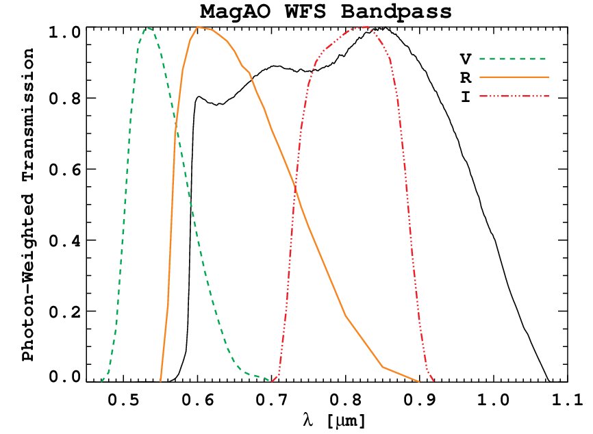
The PWFS of the MagAO-X system consists of an achromatic pyramid, a camera lens, and an OCAM2K EMCCD detector. The MagAO-X pyramid wavefront sensor is designed to operate from 600-1000nm bandwidth and a field of view of two arcseconds. Figure 1 is the bandpass of the MagAO PWFS. We expect a similar transmission for the MagAO-X PWFS.
A new camera lens is designed to meet the requirements of the MagAO-X system. These requirements are listed in Table 1. The OCAM2K will be used in 2x2 binning mode, giving us a 48 m pixel size. This allows the wavefront sensor to be run at 3.6 kHz. We have chosen a pupil size of 56 pixels across each of the pupils, which is slightly oversampled to prevent aliasing of the higher order modes. The pupil separation of 60 pixels was chosen to maximize the OCAM2K detector.
| Parameter | Requirement |
|---|---|
| Wavelength Range | 600- 1000 nm |
| Pupil Size | 56 pixels; 2.688 mm |
| Pupil Separation | 60 pixels; 2.880 mm |
| Pupil Tolerances | 1/10th pixel; 2.4 m |
| Lens Diameter | 10 mm D 20 mm |
3.1 Pyramid Design
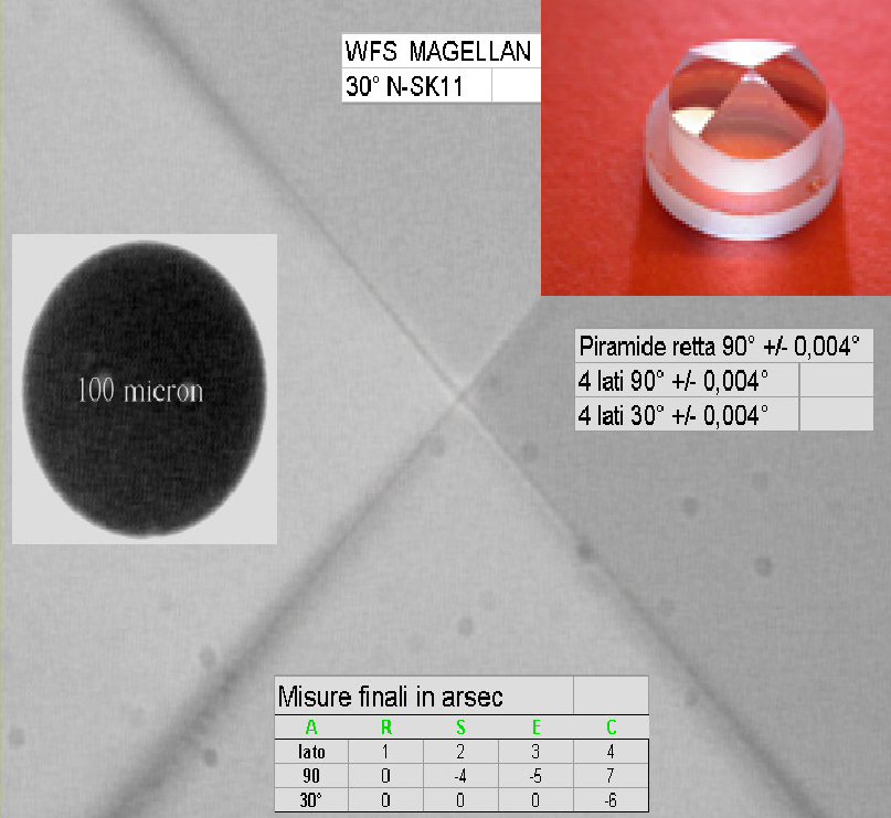
MagAO-X will be using an excellent achromatic pyramid with a 5 tip. The pyramid used in the WFS is a double pyramid, consisting of two four sided prisms aligned back to back. Details of the design done by Tozzi et. al. are summarized here.[7] A picture of the pyramid is shown in Figure 2. The total deviation angle needed for the pyramid wavefront sensor is hard to manufacture. Combining two pyramids makes the polishing process easier and at the same time allows us to control chromatic aberrations by using two different glass types. The glass types were chosen using an I.D.L. optimization routine that selected glass combinations from the Shott and Ohara catalog that would give a suitable deflection angle of the double pyramid. The front prism is made from Shott N-SK11, and the back prism is made from Schott N-PSK53.
3.2 Wavefront Sensor Design
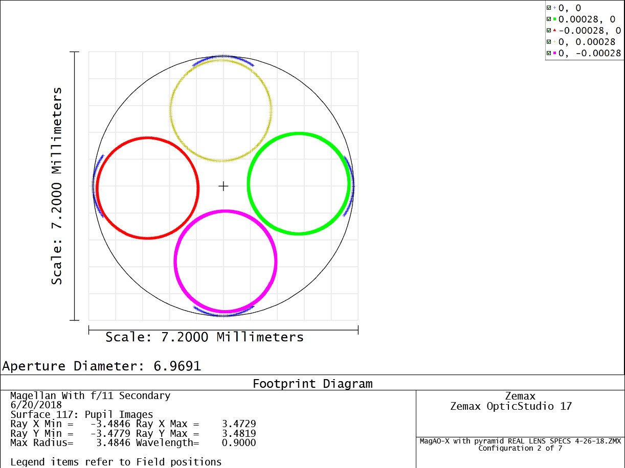
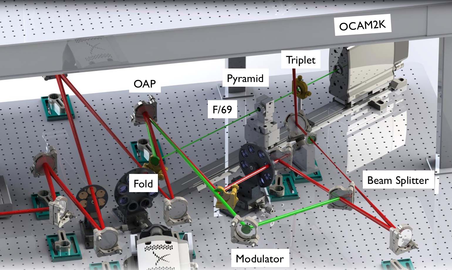
A design of the wavefront sensor is done in Zemax. An F/69 focus created by an off-axis parabolic mirror is imaged onto the pyramid tip. A custom achromatic triplet then images four pupils onto our OCAM2K wavefront sensor camera. A layout of the wavefront sensor optical path done in both Zemax and SolidWorks is shown in Figure 4. We reuse the same off axis parabolic mirror seen by the coronagraph arm of MagAO-X. The double pyramid was modeled by the Arcetri team in Zemax, and that same model is used here. A custom achromatic triplet was designed to give the correct pupil size and separation. The two windows in the OCAM2K detector are included in the design for completeness. The expected pupil footprint on the image plane for 800 nm wavelength is given in Figure 3.
3.3 Achromatic Triplet Design
The size and separation of the pupils on the detector directly affects the performance of the PWFS. If the pupils are undersized, there will be aliasing in reconstruction of the higher order modes. If the separation between pupils is not correct, complications will arise when pixels are binned on the detector to change the pupil sampling and the integration time. To ensure the correct size and separations a custom achromatic triplet was designed in Zemax. A schematic of the lens is shown in Figure 5.

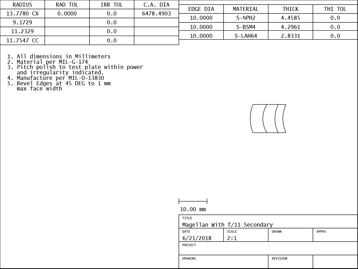
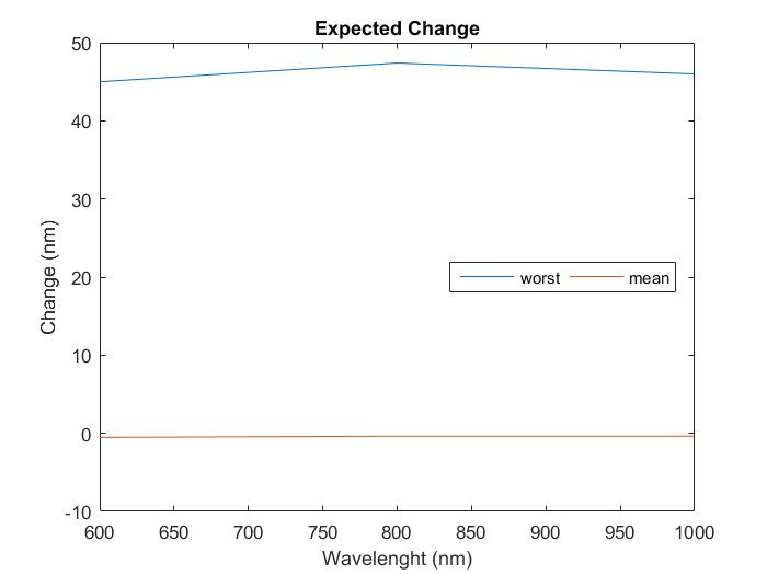
A tolerance analysis to determine lens performance as a function of wavelength is done using parameters from the Precision grade Optimax manufacturing tolerancing chart. Reasonable values of alignment errors were estimated and included in the tolerancing analysis. The figure of merit used was the RMS angular radius of the lens because the pyramid is an afocal system. A 500 trial Monte Carlo simulation was done for three wavelengths, 600nm, 800nm, and 1000nm. At each wavelength the nominal, mean, and worst RMS angular size (twice the angular radius) was recorded. The difference of the mean and worst angles with respect to the nominal value was calculated. That change in angle was propagated through the system to estimate the change in size we would expect. The propagation is shown in Figure 6, where is the nominal RMS angular size, and is the change in RMS angular size we use to calculate the estimated change . The distances were taken from the Zemax design, and the indexes correspond to air, BK-7, and Sapphire respectively. The index of refraction was adjusted for the different wavelengths when the propagation was calculated using trigonometry and Snell’s law. The results are summarized in Figure 7, where the change in size in nanometers is graphed against wavelength. At worst we expect about a 45 nm change in pupil size and separation, but no change on average. Both are well within our tolerance of the change being no greater than 1/10th a pixel, or 2.4m.

4 System Performance
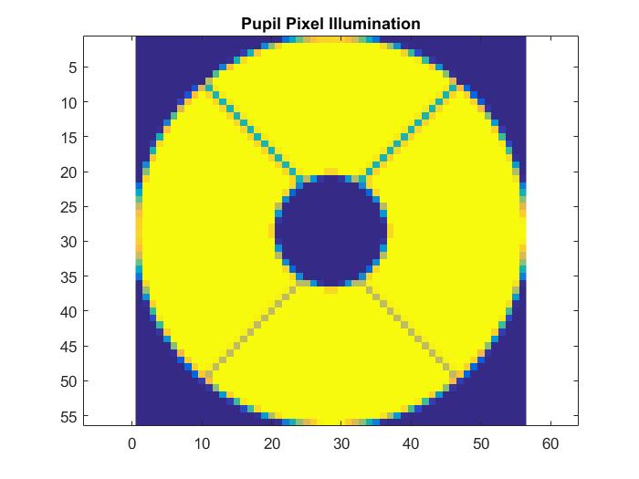
A simulation of the expected partial illumination of pupil pixels was done in MATLAB. A binary model of the MagAO-X pupil was generated with 10 times the spatial sampling than our expected PWFS pupil. We then bin it down to the expected pupil sampling of our PWFS. That is, we start with a pupil of 560 by 560 pixels, and bin down to a 56 by 56 pixel pupil by summing 10 by 10 pixel bins and normalizing. The expected illumination pattern is shown in Figure 8. A table of the pixel counts is given in Table 2. We expect 1958 fully illuminated pixels within our pupil.
| Illumination | of Actuators |
|---|---|
| 100 | 1958 |
| 90 | 166 |
| 80 | 24 |
| 0 | 46 |
| 60 | 20 |
| 50 | 18 |
| 50 | 904 |
5 Initial Results
The camera triplet was manufactured by Rainbow optics and the as-built specifications of the lens was incorporated into the Zemax design. The tolerance of our system was that the pupil size and separation was to be good to 1/10th of a pixel. We found that our fabricated lens was slightly under specifications. The pupils are slightly oversized, and the pupil separation is too close together. We believe this lens can still work for us however, because by iteratively adjusting the positions of the camera lens and camera with respect to each other and the pyramid optic, the sizes and separations of the pupils change. Usually there is a trade off between pupil size, and their seperations for small adjustments in alignment. Meaning, that if you make your pupils smaller, the separation between pupils increases. Table 3 shows the system requirements of the MagAO-X system, and the expected performance with our fabricated lens.
| Parameter | Requirement | As Built |
|---|---|---|
| Wavelength Range | 600- 1000 nm | 600-100 nm |
| Pupil Size | 56 pixels; 2.688 mm | 2.696 mm |
| Pupil Separation | 60 pixels; 2.880 mm | 2.857 mm |
| Pupil Tolerances | 1/10th pixel; 2.4 m | =8 , =-23 |
| Lens Diameter | 10 mm D 20 mm | D= 10.1 mm |
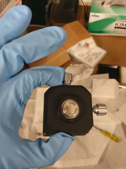
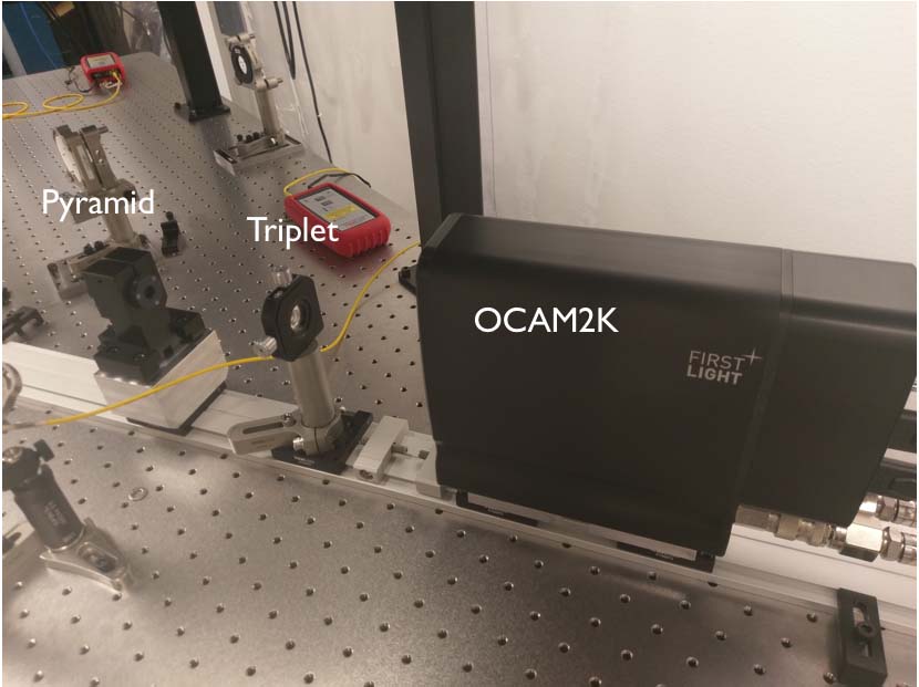
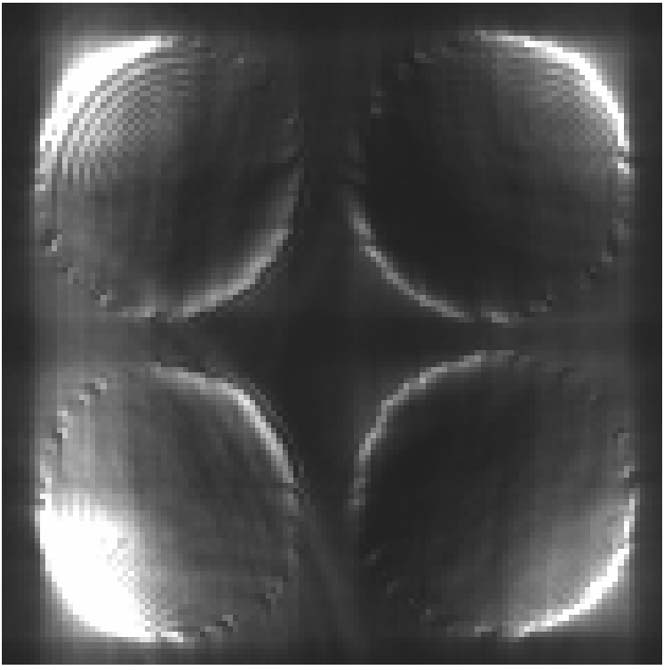
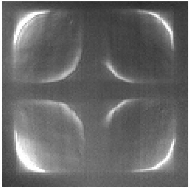
An initial alignment of the MagAO-X pyramid wavefront sensor was done using a HeNe single mode fiber laser, two off axis parabolic mirrors, and a temporary pupil mask with coarse edges. The pyramid was not modulated during alignment. The pyramid optic, camera lens, and OCAM2K were mounted on a coaxial rail system from ThorLabs. Custom mounting plates were fabricated for each optic, so that each could be mounted onto rail carriages and meet the beam height requirement of 5 inches. Figure 9 shows the mounted camera lens, and the initial alignment of the pyramid wavefront sensor. Images of the unmodulated pupils are shown in Figure 10. Figure 10 (a) shows the pupils illuminated by a HeNe fiber laser. The edge of the pupil is unclean due to the coarse edges of our temporary pupil. Figure 10 (b) shows the pupils illuminated with a white light source. An iris was put in front of the fake pupil in the system to clean up the edges of the pupil.
6 Conclusions and Future Work
The MagAO-X pyramid wavefront sensor has been optimized for wavefront sensing from 600 to 1000 . A custom acromatic triplet was designed in Zemax to give the appropriate pupil seperation (60 pixels center to center) and sampling (56 pixels across the pupil). We expect to control a maximum of 1958 modes on our 2048 actuator deformable mirror. Future work will see the pyramid wavefront sensor comissioned. In parallel we will be working with the University of Arizona Wavefront Control testbed to study the performance of different pyramid architectures and reconstruction matrices.
References
- [1] J. R. Males, MagAO-X team, “MagAO-X Preliminary Design Review”, Technical document. (April 24, 2017)
- [2] K. M. Morzinski, L. M. Close, J. R. Males, D. Kopon, P. M. Hinz, S. Esposito, A. Riccardi, A. Puglisi, E. Pinna, R. Briguglio, M. Xompero, F. Quirós-Pacheco, V. Bailey, K. B. Follette, T. J. Rodigas, Y. Wu, C. Arcidiacono, J. Argomedo, L. Busoni, T. Hare, A. Uomoto, A. Weinberger, “MagAO: Status and on-sky performance of the Magellan adaptive optics system”, Proc. SPIE 9148, Adaptive Optics Systems IV, 914804 (21 July 2014); doi: 10.1117/12.2057048; http://dx.doi.org/10.1117/12.2057048
- [3] T. Currie, O. Guyon, F. Martinache, C. Clergeon, M. McElwain, C. Thalmann, N. Jovanovic, G. Singh, T. Kudo, “The Subaru Coronagraphic Extreme Adaptive Optics Imager: First Results and On-Sky Performace”. Proc. IAU 299/Victoria conference proceedings. (15 July 2013); arXiv:1307.4093
- [4] J. R. Males, L. M. Close, K. Miller, L. Schatz, D. Doelman, J. Lumbres, F. Snik, A. Rodack, J. Knight, K. V. Gorkom, J. Long, A. Hedglen, M. Kautz, N. Jovanovic, K. Morzinski, O. Guyon, E. Douglas, J. Lozi, C. Bohlman, O. Durney, V. Gasho, P. Hinz, M. Ireland, M. Jean, C. Keller, M. Kenworthy, B. Mazin, J. Noenickx, K. Perez, A. Sanchez, C. Sauve, A. Weinberger, A. Conrad,“ MagAO-X: Project Status and First Laboratory Results”, Proc. SPIE 10703, Adaptive Optics Systems VI, 10703-9 (29 June 2018).
- [5] L. M. Close, J. R. Males, O. Durney, C. Sauve, M. Kautz, A. Hedglen, L. Schatz, J. Lumbres, K. Miller, K. V. Gorkom, M. Jean, V. Gasho, “Optical and mechanical design of the extreme AO coronagraphic instrument MagAO-X”. Proc. SPIE 10703, Adaptive Optics Systems VI, 10703-21 (29 June 2018).
- [6] R. Ragazzoni, “Pupil plane wavefront sensing with an oscillation prism”, Journal of Modern Optics. (30 May 1995); http://dx.doi.org/10.1080/09500349608232742
- [7] A. Tozzi, P. Stefanini, E. Pinna, S. Esposito, “The Double Pyramid wavefront sensor for LBT”, in Adaptive Optics Systems, Proceedings of SPIE, (2008). Vol. 7015, 701558