Dephasing-insensitive quantum information storage and processing with superconducting qubits
Abstract
A central task towards building a practical quantum computer is to protect individual qubits from decoherence while retaining the ability to perform high-fidelity entangling gates involving arbitrary two qubits. Here we propose and demonstrate a dephasing-insensitive procedure for storing and processing quantum information in an all-to-all connected superconducting circuit involving multiple frequency-tunable qubits, each of which can be controllably coupled to any other through a central bus resonator. Although it is generally believed that the extra frequency tunability enhances the control freedom but induces more dephasing impact for superconducting qubits, our results show that any individual qubit can be dynamically decoupled from dephasing noise by applying a weak continuous and resonant driving field whose phase is reversed in the middle of the pulse. More importantly, we demonstrate a new method for realizing two-qubit phase gate with inherent dynamical decoupling via the combination of continuous driving and qubit-qubit swapping coupling. We find that the weak continuous driving fields not only enable the conditional dynamics essential for quantum information processing, but also protect both qubits from dephasing during the gate operation.
The advantage of quantum computation is based on the ability of storing and processing information encoded in a collection of qubits, which are in superposition states. An obstacle against implementation of a complex quantum algorithm is the decoherence effect, arising from the inevitable interaction between the quantum machine and its environment. Protecting quantum information from decoherence is therefore essential for realization of a practical quantum computational task; the strategy depends on the properties of the noise. When the qubits are identically coupled to the environment, decoherence due to random phase errors can be suppressed by storing the quantum information in a decoherence-free subspace–encoding a logic qubit into two physical qubits Zarnadi1997PRL ; Lidar1998PRL ; Duan1998PRA . With a suitable choice of the logic basis states, any superposition of these states remains invariant under collective dephasing, corresponding to a decoherence-free state.
When the noises on different qubits are uncorrelated, there does not exist such decoherence-free subspace; this is the case for superconducting circuits, where the noises are localized around individual physical qubits. In this case, an effective strategy to suppress dephasing is dynamical decoupling (DD), achieved by periodically applying a series of pulses to the quantum system to refocus the system-environment evolution Viola1998PRA ; Khodjasteh2005PRL ; Uhrig2007PRL . Recent experiments have demonstrated significant improvement of the coherence times of quantum memories resulting from the pulsed DD JFDu2009nature ; Biercuk2009nature ; Damodarakurup2009PRL ; Lange2010science ; Ryan2010PRL ; Souza2011PRL ; Naydenov2011PRB ; Bylander2011nphys ; Sar2012nature . However, implementation of this method may be challenging for systems with fast fluctuating noise, since it requires that the delay between the pulses be shorter than the correlation time of the fluctuating environment. Another problem is how to combine the decoupling scheme with gate operations, so that dephasing is suppressed during both the information storage and processing.
An alternative way for DD is to replace pulse sequences with continuous driving fields, which is not subject to the physical restriction associated with the pulsed approach Torrey1949PR ; Fanchini2007PRA ; JMCai2012NJP . Another benefit of using continuous driving is that DD can be easily incorporated into two-qubit logic operations, as theoretically proposed Zheng2002PRA ; Bermudez2012PRA and experimentally demonstrated with trapped ions TRTan2013PRL . However, the integration of DD sequences with quantum gates in a scalable architecture like superconducting circuits remains a nontrivial open problem Paladino2014 . Two types of entangling gates with superconducting qubits, the adiabatic controlled phase gate Barends2014nature and the cross-resonance gate Sheldon2016 , have been demonstrated with fidelity values approaching the fault-tolerant threshold. But both gates do not take advantage of DD, and are only appropriate to neighboring qubits with direct couplings in a circuit with limited connectivity, which could significantly raise the algorithmic complexity McKay2017 . Here we propose and demonstrate a dephasing-insensitive quantum computation scheme in an all-to-all connected superconducting circuit featuring multiple frequency-tunable qubits connected by the central bus resonator, where a weak microwave drive dresses each qubit and protects it from dephasing during both the information storage and processing. The advantage of the frequency tunability is that the couplings between qubits can be dynamically switched on and off by tuning these qubits on- and off-resonance, respectively. However, such tunability enabled by the on-chip flux coil also incurs more flux noise when the qubit is tuned away from its sweetpoint, i.e., the maximum frequency. It is in this scenario that our scheme comes into play with a huge benefit. With the application of the driving field, the observed pure dephasing time is prolonged significantly compared with the spin echo method. For implementation of the two-qubit entangling gate, the microwave drives not only help to realize the conditional dynamics without employing non-computational states, but also protect the operation from dephasing. The scheme works no matter whether the qubits are coupled through a resonator Paik2016 or capacitor/inductor, and high-fidelity gates are promising with further improvements in the device design.
We first show how a qubit, with its bare upper and lower energy levels denoted as and , respectively, can be protected from dephasing under a continuous and resonant driving field. In the frame rotating at the qubit frequency, the Hamiltonian for the system is
| (1) |
where is the reduced Planck constant, () is the qubit raising (lowering) operator, is a function of time representing the qubit frequency fluctuation due to the presence of noise, and and are the Rabi frequency and phase of the driving field, respectively. The continuous drive creates two dressed states, and , that are separated by an energy gap . In the basis , we can rewrite as
| (2) |
We assume that the noise correlation time is much longer than the dynamical time scale , so that the fluctuation is adiabatic with respect to the Rabi oscillation. With this assumption and under the condition , the noise does not induce transitions between the two dressed states; instead it leads to energy shifts of the dressed states. The resulting effective Hamiltonian is
| (3) |
The effective qubit-environment coupling is reduced by a factor , which therefore produces a significantly reduced phase difference (phase error), , between and during the time interval [, ]. In addition, the part of originating from the slowly-varying component of can be further reduced by employing a spin-echo like technique with a -phase shift of the driving field in the middle of [, ]: The integrand in reverses sign due to the -phase shift, and as a consequence, for a slow varying , the phase error accumulated during the first half of [, ] exactly cancels out that of the second half. This single-qubit dynamical decoupling procedure, which is analogous to the rotary echo technique originally demonstrated with nuclear spins Solomon1959PRL , is named 1Q-DD here and below in contrast to the two-qubit case.
To incorporate the DD procedure into the implementation of a two-qubit controlled phase gate, we consider the system consisting of two on-resonantly coupled qubits, Q1 and Q2, each resonantly driven by a classical field for the gate operation as well as for DD protection, named 2Q-DD here and below. In the interaction picture (qubit reference frame), the Hamiltonian is
| (4) |
where h.c. stands for Hermitian conjugate, is the qubit-qubit excitation swapping rate, and and are the Rabi frequency and phase, respectively, of the drive applied to Qj, which produces two dressed states and . For simplicity, here the qubit frequency fluctuations, described by in Eq. (1), are not included, whose effects are suppressed by application of the continuous drives as discussed above. Under the conditions and , the qubits cannot undergo transitions between different dressed states due to the energy gaps produced by the drives. Then the system dynamics can be approximately described by the effective Hamiltonian (see Supplemental Material)
| (5) |
where . The first term results in conditional phase shift in the dressed state basis, which is responsible for the two-qubit entangling gate. The terms in summation are for single-qubit rotations, which produce null effect if and of both driving fields are reversed by right in the middle of the two-qubit interaction time . Then the two-qubit dressed states evolve as
| (6) |
where . With the state evolution in Eq. (6) naturally yields a conditional phase gate in the dressed state basis. For simplicity, we take , and then the corresponding unitary matrix in the two-qubit computational basis {, , , } is given by
| (7) |
Together with single-qubit rotations which incur extra phase factors between and for both qubits, this operation is equivalent to a controlled phase gate, where the phase of the two-qubit system is effectively shifted by if and only if the system is in the state . We note that the dressed state phase gate cannot be produced without the continuous drives.
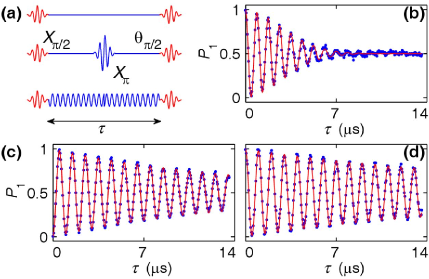

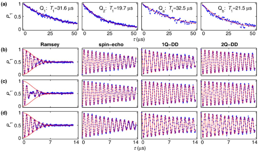
We benchmark the dephasing-insensitive scheme with a circuit quantum electrodynamics (QED) architecture consisting of multiple frequency-tunable transmon qubits connected by a fixed-frequency ( GHz) resonator, which is used to mediate the qubit-qubit interaction CSong2017a required for the two-qubit gate. Here we take a representative qubit, Q1, with an energy relaxation time s operating at 5.643 GHz, the gate point that is 152 MHz below , as an example to illustrate the suppression of dephasing using our 1Q-DD procedure. We first decouple this qubit from other qubits by tuning them far off-resonance, and initialize it to by idling for more than 200 s. Figure 1 shows the qubit -state probabilities as functions of the interval between two Ramsey pulses under free decay, spin-echo Hahn1950PR , and 1Q-DD, with the corresponding pulse sequences shown in Fig. 1(a). The Gaussian dephasing time Averin2016PRL estimated from Fig. 1(b) is s, and dramatic improvements of phase coherence are observed in Figs. 1(b) and (c). Since the interferometry data are limited to s due to our hardware constraints and the fitted dephasing time in Figs. 1(c) and (d) could be much longer, here and below we introduce a single exponential term with a time constant to describe the combined energy decay and dephasing impact for more confidence of the fitted value. s in Fig. 1(c) and s in Fig. 1(d), which correspond to a spin-echo of 20.2 s and a 1Q-DD of 35.9 s, respectively. We note that, in a recent experiment Gustavsson2012PRL , the rotary echo technique was used to mitigate the dephasing due to slow fluctuations in the drive amplitude.
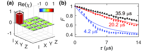
More convincingly, we can store quantum information in the qubit and examine the storage integrity using the single-qubit quantum process tomography (QPT) to witness the effectiveness of our dephasing-insensitive 1Q-DD scheme. The QPT is achieved by preparing a set of 6 input states via the single-qubit gates {, , , }, and measuring the resulting density matrices and those after the storage through quantum state tomography Zheng2017 . An example of the process matrix after a storage of 5 s is shown in Fig. 2(a), and the fidelity as a function of the storage time is shown in Fig. 2(b). For comparison, we also measure the matrices for the cases under free decay and with the spin-echo technique during the storage, both yielding lower fidelities. Numerical simulations (lines) using and the listed values for in Fig. 2(b) further confirm that the 1Q-DD scheme is efficient in protecting the qubit from dephasing.
Now we turn to the 2Q-DD scheme for realizing the two-qubit entangling gate by adding the second qubit, Q5 in Ref. CSong2017a with s, which is re-labeled as Q2 here and below for the clarity of the presentation. Q1 and Q2 both physically connect to the central bus resonator with the coupling strengths of MHz and MHz, respectively, and there is no direct coupling between these two qubits when they are far detuned in frequency. We can switch them on-resonance by tuning their frequencies to the same value which is detuned from the resonator frequency. With this setting, these two qubits are directly coupled through virtual photon exchange mediated by the resonator (see Ref. SBZheng2000PRL and Supplemental Material). For any specific measurement with the pulse sequence shown in Fig. 3(a), we first initialize Q1 and Q2 at 5.613 and 5.673 GHz, respectively, by creating any two-qubit product state using single-qubit rotations, while all other qubits are far detuned. We then apply square Z pulses to both qubits, tuning them on-resonance, so that these two qubits are red-detuned from the resonator by the same amount of 152 MHz, the gate point. When the resonator is initially in the vacuum state, the effective qubit-qubit coupling in Eq. (4) is measured to be MHz with the two-qubit population swap process. In Figs. 3(b) and (c), we present the measured (dots) and simulated (lines) two-qubit populations as functions of the gate duration, in the presence of the external driving fields, for the initial states of and , respectively. As expected, for the input state , the states and periodically exchange populations, while and are almost unpopulated throughout the gate duration; for the input state , the observed anticorrelation between the populations of and of are also in good agreement with theoretical predictions. We note that in the Lindblad master equation simulations CSong2017a in Figs. 3(b) and (c) the pure dephasing times are set to those obtained using the interferometry data exemplified in Fig. 3(d). As shown in Fig. 3(d), with both qubits at the gate point and Q2 initialized in the dressed state , the Ramsey interference pattern of Q1 with 2Q-DD yields s and s. of the 2Q-DD procedure is indeed longer than that of 1Q-DD, which has been verified previously CSong2017a ; Xu2018 .
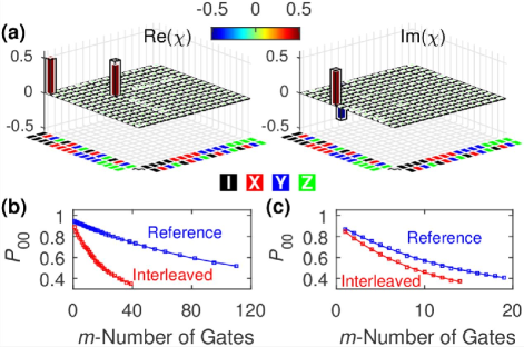
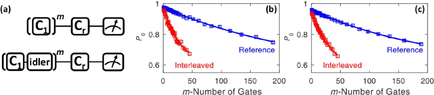
At ns, the Q1-Q2 interaction with 2Q-DD realizes . To characterize this gate, we perform the two-qubit QPT by preparing a full set of 36 distinct input states through the two-qubit gates {, , , }{, , , }2. We present the ideal and experimental process matrices and in Fig. 4(a), finding a gate fidelity of . Randomized benchmarkings (RBs) performed by inserting between random Pauli- and Clifford-based gates are shown in Figs. 4(b) and (c), which yield consistent gate fidelity values of and , respectively.
Numerical simulations suggest that our measured gate fidelity above 0.97 is consistent with the qubit values obtained in the 2Q-DD procedure, where approximately 30% of the total error are due to , 10% due to , and 60% due to limited anharmonicites of the qubits. As the dephasing is effectively suppressed by continuous drives (see Supplemental Material for more experimental data and discussions), the resulting error can be further reduced by using devices with longer qubit , stronger qubit-qubit coupling, and larger qubit anharmonicity Lv2012 . We perform a numerical simulation with the parameters MHz, MHz, MHz, s, a pure dephasing time of s, and an anharmonicity of 0.5 GHz You2007 ; Yan2016ncomms , and find a gate fidelity above 99.3% that approaches the fault-tolerant threshold Barends2014nature ; Sheldon2016 . Here and are reasonably low, which help to minimize the crosstalk issue (see Supplemental Material) so that the two-qubit gate with the dephasing-insensitive 2Q-DD scheme is applicable in the all-to-all connected circuit.
In conclusion, we have proposed and demonstrated a dephasing-insensitive
method for storing and processing quantum information in an all-to-all superconducting
circuit. The results show that the continuous, but weak, driving fields with phase reversals
at the middle of the storage time can
dynamically decouple the qubits from dephasing noise.
We integrate this DD procedure with a
two-qubit quantum logic gate by applying weak continuous drives, which not only
enable the high-fidelity entangling gate for two coupled qubits
without invoking a non-computational state, but also protect the qubits from
dephasing noise during the gate operation.
Acknowledgments. This work was supported by the National Basic Research Program of China under Grants No. 2014CB921201 and No. 2014CB921401, the National Natural Science Foundations of China under Grants No. 11674060, No. 11434008, No. 11574380, and No. 11374344, and the Fundamental Research Funds for the Central Universities of China (Grant No. 2016XZZX002-01). Devices were made at the Nanofabrication Facilities at Institute of Physics in Beijing, University of Science and Technology of China in Hefei, and National Center for Nanoscience and Technology in Beijing.
References
- (1) P. Zanardi and M. Rasetti, Phys. Rev. Lett. 79, 3306 (1997).
- (2) D. A. Lidar, I. L. Chuang, and K. B. Whaley, Phys. Rev. Lett. 81, 2594 (1998).
- (3) L.-M. Duan and G.-C. Guo, Phys. Rev. A 57, 737 (1998).
- (4) L. Viola and S. Lloyd, Phys. Rev. A 58, 2733 (1998).
- (5) K. Khodjasteh and D. A. Lidar, Phys. Rev. Lett. 95, 180501 (2005).
- (6) G. S. Uhrig, Phys. Rev. Lett. 98, 100504 (2007).
- (7) J. Du, X. Rong, N. Zhao, Y. Wang, J. Yang and R. B. Liu, Nature 461, 1265 (2009).
- (8) M. J. Biercuk, H. Uys, A. P. VanDevender, N. Shiga, W. M. Itano and J. J. Bollinger, Nature 458, 996 (2009).
- (9) S. Damodarakurup, M. Lucamarini, G. Di Giuseppe, D. Vitali, and P. Tombesi, Phys. Rev. Lett. 103, 040502 (2009).
- (10) G. de Lange, Z. H. Wang, D. Riste, V. V. Dobrovitski, and R. Hanson, Science 330, 60 (2010).
- (11) C. A. Ryan, J. S. Hodges, and D. G. Cory, Phys. Rev. Lett. 105, 200402 (2010).
- (12) A. M. Souza, G. A. Alvarez, and D. Suter, Phys. Rev. Lett. 106, 240501 (2011).
- (13) B. Naydenov, F. Dolde, L. T. Hall, C. Shin, H. Fedder, L. C. L. Hollenberg, F. Jelezko, and J. Wrachtrup, Phys. Rev. B 83, 081201(R) (2011).
- (14) J. Bylander et al., Nat. Phys. 7, 565 (2011).
- (15) T. van der Sar et al., Nature 484, 82 (2012).
- (16) H. C. Torrey, Phys. Rev. 76, 1059 (1949).
- (17) F. F. Fanchini, J. E. M. Hornos, and R. d. J. Napolitano, Phys. Rev. A 75, 022329 (2007).
- (18) J.-M. Cai, B. Naydenov, R. Pfeiffer, L. P. McGuinness, K. D. Jahnke, F. Jelezko, M. B. Plenio, and A. Retzker, New J. Phys. 14, 113023 (2012).
- (19) S.-B. Zheng, Phys. Rev. A 66, 060303(R) (2002).
- (20) A. Bermudez, P. O. Schmidt, M. B. Plenio, and A. Retzker, Phys. Rev. A 85, 040302(R) (2012).
- (21) T. R. Tan, J. P. Gaebler, R. Bowler, Y. Lin, J. D. Jost, D. Leibfried, and D. J. Wineland, Phys. Rev. Lett. 110, 263002 (2013).
- (22) E. Paladino, Y. M. Galperin, G. Falci, B. L. Altshuler, Rev. Mod. Phys. 86, 361 (2014).
- (23) R. Barends et al., Nature 508, 500 (2014).
- (24) S. Sheldon, E. Magesan, J. M. Chow, and J. M. Gambetta, Phys. Rev. A 93, 060302(R) (2016).
- (25) D. C. McKay, S. Sheldon, J. A. Smolin, J. M. Chow, and J. M. Gambetta, arXiv:1712.06550.
- (26) H. Paik et al., Phys. Rev. Lett. 117, 250502 (2016).
- (27) I. Solomon, Phys. Rev. Lett. 2, 301 (1959).
- (28) C. Song et al., Phys. Rev. Lett. 119, 180511 (2017).
- (29) K. Xu et al., Phys. Rev. Lett 120, 050507 (2018).
- (30) E. L. Hahn, Phys. Rev. 80, 580 (1950).
- (31) D. V. Averin, K. Xu, Y.P. Zhong, C. Song, H. Wang, and S. Han, Phys. Rev. Lett. 116, 010501 (2016).
- (32) S. Gustavsson et al., Phys. Rev. Lett. 108, 170503 (2012).
- (33) Y. Zheng et al., Phys. Rev. Lett. 118, 210504 (2017).
- (34) S.-B. Zheng and G.-C. Guo, Phys. Rev. Lett. 85, 2392 (2000).
- (35) X.-Y. Lu, S. Ashhab, W. Cui, R. Wu, and F. Nori, New J. Phys. 14, 073041 (2012).
- (36) J. Q. You, X. Hu, S. Ashhab, and F. Nori, Phys. Rev. B 75, 140515(R) (2007).
- (37) F. Yan et al., Nat. Commun. 7, 12964 (2016).
Supplementary Material for “Dephasing-insensitive quantum information storage and processing with superconducting qubits”
1 Effective qubit-qubit interaction under a strong drive
In the basis formed by the dressed states and , the qubit flip operators and can be expressed, respectively, as
where , and . With this, we can rewrite the Hamiltonian of Eq. (4) of the main text as
| (S1) |
where . The energy gap between the dressed states and produced by the driving term is . Under the condition , the qubits cannot undergo transitions between different dressed states due to the large detunings, so that the terms containing can be neglected. We note that, when or , the strong driving condition can be somewhat loosened. We here take as an example. With this setting, reduces to
| (S2) |
In this case, the second and third terms in the parentheses correspond to the coupling between the two dressed states and with an energy gap , while the last two terms in the parentheses describe the coupling between and with an energy gap . When , these couplings do not induce transitions between different dressed states due to large detunings and thus can be discarded. Then the system Hamiltonian reduces to Eq. (5) of the main text.
2 Selective resonator-induced qubit-qubit interaction
When Q1 and Q2 are red-detuned from the resonator by the same amount that is much larger than the qubit-resonator couplings and , they are coupled through virtual photon exchange mediated by the resonator SBZheng2000PRL . If each of the other qubits is far off-resonance with the resonator, Q1, and Q2, the Q1-Q2 dynamics is not affected by the other qubits and the photon number of the resonator remains unchanged during the interaction. When the resonator is initially in the vacuum state, the effective Hamiltonian for Q1 and Q2 is given by SBZheng2000PRL
| (S3) |
where
and . The vacuum-induced Stark shifts described by can be compensated for by suitably adjusting the frequencies of Q1 and Q2, so that the effective Hamiltonian reduces to . The magnitude of the experimentally measured qubit-qubit coupling is slightly smaller than for the existence of the direct coupling CSong2017a between Q1 and Q2, which partly cancels out the resonator-induced coupling whose sign is opposite to that of the direct coupling.
3 Device information
The physical device used in our experiment is the same as that reported in Ref. CSong2017a , which consists of 10 frequency-tunable transmon qubits interconnected by a fixed-frequency central bus resonator . The bus resonator is a superconducting half-wavelength coplanar waveguide resonator with 10 side arms, and each arm capacitively couples to one qubit. Figure S1 shows a sketch of the device. More details on the device and the wiring configuration can be found in Supplemental Material of Ref. CSong2017a .
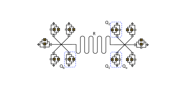
Owing to the all-to-all connectivity, arbitrarily selected two qubits can be coupled by detuning them from the bus resonator by the same amount in frequency. In the main text, we have described the experiment using Q1 and Q2 to implement the gate. In this Supplemental Material, we provide additional data obtained in another experiment which was performed in a separate cooldown, where qubit conditions changed so that we have to replace Q2 by another qubit, Qb, and rename Q1 as Qa for the clarity of the presentation. Relevant qubit parameters at the interaction frequency for the gate are summarized in Table S1, with the experimental data shown in Fig. S2.
| (GHz) | (s) | (s) | (MHz) | gate length (ns) | |
|---|---|---|---|---|---|
| Q1 | 5.643 | 31.6 | 4.2 | 14.2 | 215.0 |
| Q2 | 19.7 | 3.4 | 15.2 | ||
| Qa | 5.610 | 32.5 | 3.2 | 14.2 | 210.7 |
| Qb | 21.5 | 3.5 | 16.3 |
4 Qubit pure dephasing times obtained in different procedures
The randomized benchmarking (RB) sequences can estimate higher gate fidelities due to their resemblance to DD sequences when low-frequency noise is present in the system S (1). To quantify such an effect, we have performed an additional experiment with Qa and Qb, where we bias both qubits to 185 MHz below the bus resonator for a gate length of 210.7 ns, and obtain the gate fidelity values of 0.9720 0.0011 (QPT), 0.9784 0.0012 (Pauli-based RB), and 0.9722 0.0062 (Clifford-based RB).
We define the idler gate where the target qubit is idled at for the time of the gate length while the other qubit is detuned. The idler gate has been characterized using the interleaved RB sequences as illustrated in Fig. S3(a), whose fidelity is determined by the qubit and at . The idler gate fidelity is 0.9843 for Qa and 0.9884 for Qb as shown in Fig. S3(b) and (c). We note that the idler-RB , inferred from the idler gate fidelity, should indicate the enhancement of RB sequences due to their resemblance to DD sequences.
It is seen from Table S2 that idler-RB is significantly shorter than 1Q-DD and 2Q-DD . In particular, the enhancement of due to RB sequences for Qa is less obvious, indicating that RB sequences are less effective in suppressing the unknown type of noise. Our numerical simulations show that the 2Q-DD values are consistent with the measured gate fidelity values on average, which cannot be obtained with the idler-RB values. With the idler-RB values listed in Table S2, our numerical simulations suggest that the gate fidelity maximizes at about 0.96.
| spin-echo (s) | 1Q-DD (s) | 2Q-DD (s) | idler-RB | |
|---|---|---|---|---|
| Q1 | 20.2 | 35.9 | 65.6 | - |
| Q2 | 26.4 | 24.7 | 73.9 | - |
| Qa | 28.7 | 47.4 | 78.7 | 8.3 |
| Qb | 16.6 | 33.1 | 45.0 | 15.5 |
5 The crosstalk effect
Crosstalk is an inevitable topic if the circuit continues to scale up. However, we expect that the hardware issue resulting in crosstalk can be significantly improved with better circuit designs and fabrication technologies. On the other hand, the performance of our dephasing-insensitive scheme is less sensitive to the crosstalk effect due to the following reasons.
For the two on-resonant qubits, Q1 and Q2, completing the gate, the mutual crosstalk only changes the effective amplitude and phase of the microwave applied to each qubit, where the overall gate dynamics remain the same and an optimal gate is achievable by adjusting the control parameters. With an additional qubit, e.g., Qj, simultaneously driven but detuned by from the on-resonance frequency of Q1 and Q2, the crosstalk effect results in weak and dispersive microwave drives on Q1 and Q2, which produce a Stark shift () on either qubit (here is the dispersive drive strength through Qj on Q1 or Q2, and ). We note that this energy-level shift only modifies the qubit frequency fluctuation referring to Eq. (1) of the main text, whose effect is suppressed by the corresponding dynamical decoupling procedure. Therefore the microwave crosstalk effect is negligible if qubits are properly separated in frequency. If more qubits are added into the system and the whole frequency band becomes crowded, we can choose to sequentially implement gates for some qubit pairs to avoid such crowding in frequency.
References
- S (1) H. Ball, T. M. Stace, S. T. Flammia, and M. J. Biercuk, Phys. Rev. A 93, 022303 (2016).