A CT image based finite element modelling to predict the mechanical behaviour of human arm
Abstract
In the present work, complex irregular bones and joints of the complete human arm were developed in a computer aided design environment. Finite element analysis of an actual human arm was done to identify the distribution of stress using von-Mises stress and maximum principal stress measures. The results obtained from the present study revealed the region where, maximum stress was developed for different loading and boundary conditions with different joint rotations as obtained in the actual human arm. This subject specific analysis helps to analyse the region of the arm in which the risk is more.
I Introduction
The human arm poses exemplary characteristics to perform multi-tasks simultaneously. The arm poses soft and hard tissues to act in both elastic and plastic manner to handle soft, tender material with care and carry robust loads. The structure is rigid enough to take shock loads and impact loads. The load capacity of human arm, though studied through experiments cannot be universally applicable to all because of variation of properties and micro structure. At this juncture, in order to replace or repair human arm, a thorough study on stress and strain analysis is required. A finite element study of several human body parts is done in literature.
A human arm is having complex joints and capable of performing various moments. The pronation/supination and flexion/extension moment arm magnitudes with elbow angle were represented well by the computer model [1]. The trajectory of the human arm is traced [2] in order to investigate the strategies used to plan and control, multi joint arm trajectories. Zadpoor have studied the vibrations of the humerus bone by attaching two hemispheres to its both ends[3]. The bone is considered as a linear-elastic, isotropic and homogeneous material. The mechanical properties of the human arm are modulated during the examination of isometric force regulation tasks [4].
The apparent elastic modulus and viscous behavior of cardiac and skeletal muscle and vascular endothelium would differ due to functional and structural differences[5]. Analyses of the mechanics of narrowly contained tissues have used Poisson’s ratios to study the significant effect on the results[6]. Mechanical behavior of fresh human cadaver lumbar motion segments in flexion, extension, lateral bending and torsion is examined for different loading conditions[7]. Finite element analysis described an easy method to simulate the kinetics of multi-body mechanisms[8]. It is used in order to develop a musculo-skeletal model of the shoulder mechanism. Finite element model of the human hand-arm system is used to derive natural frequencies and mode shapes[9]. In the present work, in order to identify the weaker region of the human arms during movement, various case studies were conducted. In addition, an image based computer model of the human arm with soft tissue, bone and bone marrow was developed to perform the analysis more accurately.
II THREE DIMENSIONAL CAD MODELING OF HUMAN ARM
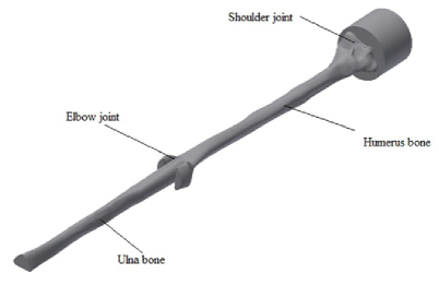
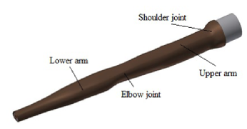
Effective methods for the conversion of computed tomography data into computer-aided design models are still in development[10]. In the present work, the following three different process paths for the generation of a computer-aided design model was used. The human arm contains different types of bones and each bone unique in its geometry. Coming from the shoulder the first is humerus head, which has most complex geometry. It is located at the shoulder joint connecting the shoulder joint and the humerus. Humerus is the midsection of the arm lies between the head and elbow. It is comparatively less complex than humerus head, but it is the longest part and maximum load taking bone. The ulna is the last bone connecting the wrist and the elbow, as shown in Fig. 1. The complete modeling to the human arm with soft tissue, bone and bone marrow have been performed in Autodesk Inventor®, as shown in Fig. 2.
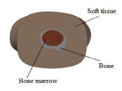
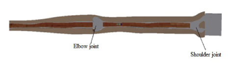
Cross sectional view, as shown in Fig. 3 has the three different parts of human arm, where outer part is soft tissue followed by the bone and the inner part is bone marrow. Fig. 4 shows the shoulder joint with spherical joint to provide 3 DOF and elbow joint with one DOF as like hinge joint. Finally, the complete assembly is exported in the IGES format to do the further finite element analysis.
The CAD model was imported into ANSYS workbench. Subsequently, the material properties of the soft tissue, bone and bone marrow were keyed into the workbench. Material properties were assigned by selecting individual part of the model. The type of contacts and joints were assigned between them. Prior to connections, co-ordinates were defined using the global co-ordinate system. Different mesh size was attributed and convergence study was performed using linear tetrahedral element. In static structure, the loading and boundary conditions were input. Finally, the stress output required from the simulation results was specified to locate the maximum stress region in the solution.
III RESULTS AND DISCUSSION
Analysis of the individual bone and complete assembly is performed in the ANSYS workbench to perform static structural analysis. To calculate the effects of steady loading conditions on the individual parts as well on the complete assembly by using the boundary condition as like human arm motion. In static analysis the material properties of bone, bone marrow and soft tissue is assigned according to the values found by [3], [5], [6], [9]. Similarly, the loading and boundary conditions for different movements of the human arm is applied in our work as used by [1], [2], [11].
III-A Static analysis of humerus and ulna bone assembly (Stress):
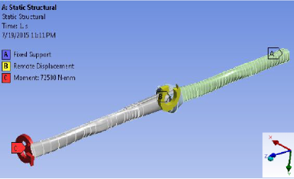
In this case, the humerus and ulna bone assembled by elbow joint for the given flexion movement with the boundary condition, as shown in Table I with respect to the co-ordinate, as shown in Fig. 5. The shoulder joint is fixed and the elbow joint is rotated along the axis, as shown in Fig. 5. The applied moment is [11] along axis at the tip of the ulna bone, as shown in Fig. 5. The humerus and ulna bone assembly is meshed using tetrahedral mesh type with mesh size.
| Serial No. | Co-ordinate | Degree |
|---|---|---|
| 1 | 145∘ | |
| 2 | 0∘ | |
| 3 | 0∘ |
III-A1 Case I
Flexion movement of ulna bone (elbow joint) is achieved with the given boundary condition as, shown in Table I w.r.t the co-ordinates, as shown in Fig. 5. The shoulder joint is fixed and the elbow joint is rotated along the axis, as shown in Fig. 5. The applied moment is [11] at the tip of the ulna bone, as shown in Fig. 5. For the given boundary and loading condition static analysis of the ulna and humerus bone is performed to study the different stress, as shown in the Table II.
| Serial No. | Stress | |
|---|---|---|
| 1 | Equivalent stress | 224.67 |
| (von-Mises stress) | ||
| 2 | Maximum Principal stress | 157.18 |
| 3 | Max Shear stress | 129.14 |
| 4 | Normal stress | 102.82 |
III-A2 Case II
Extension movement of ulna bone (elbow joint) is achieved with the given boundary condition, as shown in Table III w.r.t the co-ordinates, as shown in Fig. 5. The shoulder joint is fixed and the elbow joint is also constrained in all the three axes of rotation. The applied moment is [11] along axis at the tip of the ulna bone. For the given boundary and loading condition static analysis of the ulna and humerus bone is performed to study the different stress, as shown in the Table IV.
| Serial No. | Co-ordinate | Degree |
| 1 | 0∘ | |
| 2 | 0∘ | |
| 3 | 0∘ |
| Serial No. | Stress | |
|---|---|---|
| 1 | Equivalent stress | 130.46 |
| (von-Mises stress) | ||
| 2 | Maximum Principal stress | 91.273 |
| 3 | Max Shear stress | 74.988 |
| 4 | Normal stress | 59.706 |
The static analysis of the humerus and ulna bone is performed to study the behavior under static loading condition, before going for static analysis of the complete human arm with soft tissue, humerus bone, ulna bone and bone marrow. In the above, cases isotropic material property of the bone is assigned and the maximum stress is obtained near the elbow joint.
III-B Static analysis of muscle, bone marrow, humerus and ulna bone assembly (Stress):
III-B1 Case I
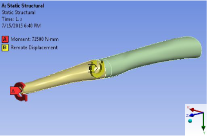
Flexion movement of the elbow (elbow joint) is achieved with the given boundary condition as shown in Table V w.r.t the co-ordinates, as shown in Fig. 6. The shoulder joint is fixed and the elbow joint is rotated along the axis, as shown in Fig. 6. The applied moment is [11] along axis at the tip of the ulna bone, as shown in Fig. 6. The humerus and ulna bone assembly is meshed using tetrahedral mesh type with mesh size. The complete human arm consists of soft tissue, humerus bone, ulna bone and bone marrow. The material properties are individually mapped to the human arm. For the given boundary and loading condition static analysis of the complete human arm is performed to study the different stress, as shown in the Table VI. The stress is maximum at ulna bone near to the elbow joint, as shown in the Fig. 7.
| Serial No. | Co-ordinate | Degree |
|---|---|---|
| 1 | 145∘ | |
| 2 | 0∘ | |
| 3 | 0∘ |
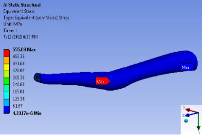
| Serial No. | Stress | |
|---|---|---|
| 1 | Equivalent stress | 555.03 |
| (von-Mises stress) | ||
| 2 | Maximum Principal stress | 408.51 |
| 3 | Max Shear stress | 320.40 |
| 4 | Normal stress | 150.44 |
III-B2 Case II
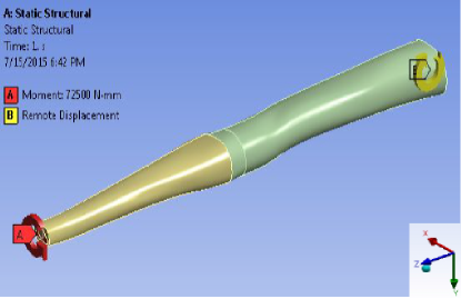
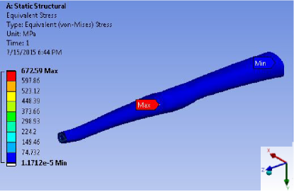
Flexion movement of the shoulder (shoulder joint) is achieved with the given boundary condition as shown in Table VII w.r.t the co-ordinates, as shown in Fig. 8. The elbow joint is fixed and the shoulder joint is rotated along the axis, as shown in Fig. 8. The applied moment is [11] along axis at the tip of the ulna bone, as shown in Fig. 8. The humerus and ulna bone assembly is meshed using tetrahedral mesh type with mesh size. For the given boundary and loading condition static analysis of the complete human arm is performed to study the different stress which is shown in the Table VIII. The material properties are individually mapped to soft tissue, humerus bone, ulna bone and bone marrow. The stress is maximum at ulna bone near the elbow joint, as shown in the Fig. 9.
| Serial No. | Co-ordinate | Degree |
| 1 | 90∘ | |
| 2 | 0∘ | |
| 3 | 0∘ |
| Serial No. | Stress | |
|---|---|---|
| 1 | Equivalent stress | 672.59 |
| (von-Mises stress) | ||
| 2 | Maximum Principal stress | 697.41 |
| 3 | Max Shear stress | 376.88 |
| 4 | Normal stress | 163.91 |
Static structural analysis of the individual bone is performed to understand various motions for the different loading and boundary conditions. To identify the failure region with complete assembly of human arm, four different theories have been used because it’s difficult to predict the ductile and brittle nature of the bone. The measure of von-Mises stress and maximum principal stress are suitable for both brittle and ductile materials. Both the theory shows the same maximum stress region for both assemblies.
IV Conclusion
The current work presents a method to model and analyse the behavior of human arm under static loading conditions with the assembly of the humerus and ulna bone. In this work, complex and irregular bones and joints of the human arm were modeled in computer-aided design environment. Finite element analysis of actual human arm was done by assigning the individual material properties to identify maximum stress region using von- Mises stress, maximum principal stress and maximum shear stress because it’s difficult to predict the ductile and brittle nature of bone. This study can help to reduce the failure at maximum stress region by taking appropriate care. Maximum stress is also obtained to identify the week region, where the stress has maximum values. The study can be extended to predict the behavior in different movements of the human arm.
References
- [1] W. M. Murray, S. L. Delp and T. S.Buchanan, “Variation of muscle moment arms with elbow and forearm position”, Journal of biomechanics, 28(5), 513-525, 1995.
- [2] W. Abend, E. Bizzi and P. Morasso, ”Human arm trajectory formation”, Brain: a journal of neurology, 105(Pt 2), 331-348, 1982.
- [3] A. A. Zadpoor, ”Finite element method analysis of human hand arm vibrations”, Int. J. Sci. Res, 16, 391-395, 2006.
- [4] E. J. Perreault, R. F. Kirsch, P. E. Crago, ”Multijoint dynamics and postural stability of the human arm”, Experimental brain research, 157(4), 507-517, 2004.
- [5] A. B. Mathura, A. M. Collinswortha, W. M. Reicherta, W. E. Krausb, G. A. Truskeya, ”Endothelial, cardiac muscle and skeletal muscle exhibit different viscous and elastic properties as determined by atomic force microscopy”, Journal of biomechanics, 34(12), 1545-1553, 2001.
- [6] W. M. Vannah and D. S. Childress, ”Modelling the mechanics of narrowly contained soft tissues: the effects of specification of Poisson’s ratio”, Journal of rehabilitation Research and development, 30, 205-205, 1993.
- [7] A. B. Schultz, D. N. Warwick, M. H. Berkson and A. L. Nachemson , ”Mechanical properties of human lumbar spine motion segments Part I: Responses in flexion, extension, lateral bending, and torsion”, Journal of Biomechanical Engineering, 101(1), 46-52, 1979.
- [8] F. C. T. van der Helm, ”A finite element musculoskeletal model of the shoulder mechanism”, Journal of biomechanics, 27(5), 551-569, 1994.
- [9] S. Adewusi, M. Thomas, V. H, Vu and W. Li, ”Modal parameters of the human hand-arm using finite element and operational modal analysis”, Mechanics and Industry, 15(6), 541-549, 2014.
- [10] A. E. Yousif and M. Y. Aziz, ”Biomechanical Analysis of the human femur bone during normal walking and standing up”, IOSR Journal of Engineering (IOSRJEN), 2(8), 13-19, 2012.
- [11] J. L. Askew, A. N. Kainan, B. F. Morrey, E. Y. S. Chao, ”Isometric elbow strength in normal individuals”, Clinical orthopaedics and related research, 222, 261-266, 1987.