Topological insulators in twisted transition metal dichalcogenide homobilayers
Abstract
We show that moiré bands of twisted homobilayers can be topologically nontrivial, and illustrate the tendency by studying valence band states in valleys of twisted bilayer transition metal dichalcogenides, in particular, bilayer MoTe2. Because of the large spin-orbit splitting at the monolayer valence band maxima, the low energy valence states of the twisted bilayer MoTe2 at () valley can be described using a two-band model with a layer-pseudospin magnetic field that has the moiré period. We show that has a topologically non-trivial skyrmion lattice texture in real space, and that the topmost moiré valence bands provide a realization of the Kane-Mele quantum spin-Hall model, i.e., the two-dimensional time-reversal-invariant topological insulator. Because the bands narrow at small twist angles, a rich set of broken symmetry insulating states can occur at integer numbers of electrons per moiré cell.
Introduction.— Moiré superlattices form in van der Waals bilayers with small differences between the lattice constants or orientations of the individual layers, and often dramatically alter electronic properties Hunt et al. (2013); Dean et al. (2013); Wang et al. (2015); Kim et al. (2017); Spanton et al. (2018); Chen et al. (2018). In the presence of long-period moiré patterns, electronic states can be described by continuum model Hamiltonians with the moiré periodicity and spinors whose dimension is equal to the total number of bands, summed over layers, in the energy range of interest. Application of Bloch’s theorem then gives rises to moiré bands Bistritzer and MacDonald (2011). Because the moiré pattern often generates spatial confinement, moiré bands can be narrow, enhancing the importance of electronic correlations. The flat bands of magic-angle twisted bilayer graphene, in which correlated insulating and superconducting states have been discovered Cao et al. (2018a, b), provide a prominent example. The study of moiré flat bands has recently become an active area of experimental and theoretical research centered on efforts to identify promising bilayer structures, and on topological characterization and many-body interaction physics Wu et al. (2018a); Po et al. (2018); Wu et al. (2018b); Naik and Jain (2018); Chittari et al. (2019); Zhang et al. (2018).
When the two layers are formed from the same material (homobilayers), both must be treated on an equal footing. The -valley valence bands of semiconductor group-VI transition metal dichalcogenide(TMD) monolayers provide a prototypical model system because strong spin-orbit coupling and broken inversion symmetry lifts spin-degeneracy Xiao et al. (2012), and the corresponding homobilayer can be described by a two-band model with layer pseudospins at each valley. The moiré pattern’s periodic modulation can then be accounted for by a scalar potential and a pseudo magnetic field whose components are the coefficients of the layer Pauli matrix expansion of the two-band Hamiltonian, i.e. and are the real and imaginary parts of the interlayer tunneling amplitude and is the potential difference between layers. The field inherits the moiré pattern periodicity and plays a key role in the discussion below.
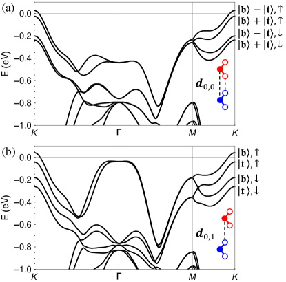
In this Letter, we focus on the MoTe2 bilayer with AA stacking [Fig. 1], for which valence band maxima are located in valleys according to our first-principles calculations as shown in the Supplemental Material(SM)SM . For this system, we find that has a skyrmion lattice texture in real space, and that the moiré bands carry valley-contrasting Chern numbers. The topological moiré bands can provide a realization of the Kane-Mele model, where the effective gauge potential is generated by the momentum shift between the two twisted layers. When the bilayer is polarized by a vertical displacement potential, the band Chern numbers are driven to zero before becomes topologically trivial in real space. In partially filled topological flat bands, interactions can, for example, break time-reversal symmetry to form quantum anomalous Hall states.
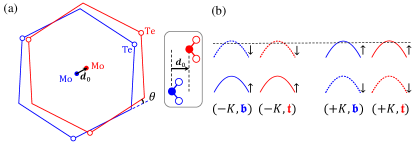
Aligned bilayers— To derive a moiré continuum Hamiltonian, we start by analyzing the electronic structure of an aligned bilayer Jung et al. (2014). Because the valleys are related by time-reversal symmetry , we can focus on the valley. In an AA stacked TMD homobilayer [Fig. 1], the valence states at the valley valence band maximum are mainly of orbital character, have spin up () along axis Xiao et al. (2012), and are separated from spin-down () states by strong spin-orbit splitting. Retaining only the spin up valence-band states at the valley yields the two-band Hamiltonian SM ,
| (1) |
with parameters that depend on the displacement between the aligned layers. In Eq. (1), and refer to bottom () and top () layers, is momentum measured from point, is the valence band effective mass that is approximately independent of SM , are layer-dependent energies, and is an inter-layer tunneling amplitude. The dependence of () on is constrained by the symmetry properties of the bilayer. The two-dimensional lattice periodicity of the aligned bilayers implies that the are periodic functions of . A mirror operation interchanges and and maps displacement to , implying that . Threefold rotation around the axis requires that and be invariant when is rotated by . These symmetry constraints lead to the following two-parameter lowest-harmonic parametrization:
| (2) |
where for the layer and for the layer, is the reciprocal lattice vector obtained by counterclockwise rotation of by angle , is the monolayer TMD lattice constant, and and respectively characterize the amplitude and shape of the potentials. Note that we have chosen the spatial averages of , which must be identical, as the zero of energy.
The dependence of is most conveniently understood by assuming a two-center approximation Bistritzer and MacDonald (2011) for tunneling between the metal orbitals, and using a lowest-harmonic approximation. This leads to,
| (3) |
where is a tunneling strength parameter. It is informative to highlight three high-symmetry displacement values: for , where are the primitive translation vectors of the aligned bilayer: and . For the metal atoms of the two layers are aligned, and ; the valence band maximum states are then symmetric and antisymmetric combinations of the isolated layer states. For the metal atoms in one layer are aligned with the chalcogen atoms in the other layer, and vanishes as a result of the threefold rotational symmetry . We determine the model parameters by fitting the eigenvalues of at the three displacements to corresponding values from fully relativistic band structure calculations using Quantum Espresso Giannozzi et al. (2009). We find that (8 meV, , meV) for MoTe2.
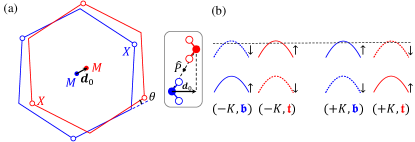
Moiré Hamiltonian.— We construct the twisted bilayer Hamiltonian by starting from an aligned bilayer with and then rotating the bottom and top layers by angles and around a metal site. (Any initial displacement just shifts the moiré pattern globally Bistritzer and MacDonald (2011); Wu et al. (2018c).) We take the origin of coordinates to be on this rotation axis and midway between layers. With respect to this origin, the bilayer has point group symmetry generated by the threefold rotation around axis and a twofold rotation around axis that swaps the two layers. In a long-period moiré pattern, the local displacement between the two layers, approximated by , varies smoothly with the spatial position Jung et al. (2014); Wu et al. (2017). The moiré Hamiltonian is
| (4) |
where is obtained by replacing in Eqs. (2)-(3) with to account for the spatial variation of the local inter-layer coordination. The moiré Hamiltonian is periodic with the moiré period . Because of the twist, the points associated with the bottom and top layers are rotated to different momenta, accounted for by the shifts in (4). We choose a moiré Brillouin zone (MBZ) in which the points are located at the MBZ corners, as illustrated in Fig. 2(a).
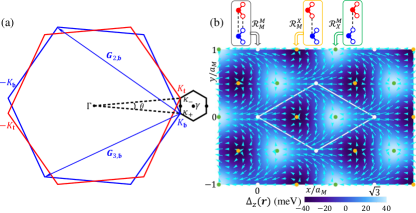
To reveal the spatial structure of the field, we define the layer pseudospin magnetic field:
| (5) |
As illustrated in Fig. 2(b), vanishes along the links that connect nearest-neighbor sites and has minimum and maximum values at and . The in-plane pseudospin field, which accounts for interlayer tunneling, has vortex and antivortex structures centered on and . Here denotes high-symmetry sites at which atoms of the bottom layer are locally aligned with atoms of the top layer. It follows that forms a skyrmion lattice, i.e., that the direction of the covers the unit sphere once in each moiré unit cell (MUC). We have explicitly confirmed this property by numerically evaluating the winding number Moon et al. (1995):
| (6) |
Skyrmion lattice pseudospin textures in position space indicate Nagaosa and Tokura (2013) the possibility of topological electronic bands in momentum space, although we will find that the connection is not one-to-one.
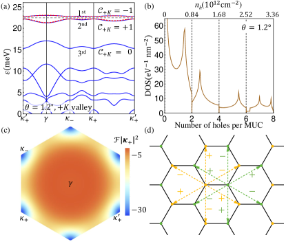
Topological bands.— The moiré band structure is illustrated in Fig. 3(a) for a representative angle . The symmetry of the Hamiltonian maps and therefore enforces degeneracy between these points. For the two topmost moiré bands of the valley, wave functions in the () layer are concentrated near the () sites, which are () maxima. Because of the layer-dependent momentum shifts in the kinetic energies, the moiré band wave functions vary rapidly over the MBZ. In particular, the wave function of the topmost moiré band at and are respectively localized in layers and . By integrating the Berry curvature over the MBZ Xiao et al. (2010), we confirm that the Chern numbers of the two topmost valley moiré bands in Fig. 3 are non-trivial () at . The corresponding bands at the valley must have the opposite Chern numbers due to the symmetry. Spin-valley locking implies that when the chemical potential is in the gap between the two topmost bands, the twisted homobilayer is not only a valley Hall insulator but also a quantum spin Hall insulator, i.e., a topological insulator Kane and Mele (2005a, b).
To gain deeper insight into the topological bands, we construct a tight binding model. The real space distribution of the wave functions suggests a two-orbital model for the first two moiré bands:
| (7) | ||||
where denotes spin (equivalent to valley ), and labels orbitals localized in the bottom (+1) and top () layers and centered around the and sites. The two orbitals form a honeycomb lattice in Fig. 3(d). In (7), the spin up and down sectors are decoupled due to the spin-valley symmetry of the low-energy theory, and are related by symmetry. The first line of (7) captures inter-layer hopping between nearest neighbors on the honeycomb lattice. Its form is constrained by the requirements that the energy spectra have threefold rotational symmetry and be identical at and points. The second line of (7) captures intralayer hopping between next nearest neighbors on the honeycomb lattice; the bond and spin-dependent phase factors , which take values of , are analogous to the Peierls substitution and account for the momentum shift in (4). The Hamiltonian (7) is equivalent to the Kane-Mele model Kane and Mele (2005a, b), and to two time-reversed-partner copies of the Haldane model Haldane (1988). It correctly captures both the topological character and the energy dispersion of the first two bands in Fig. 3(a).
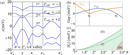
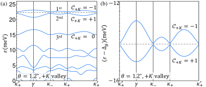
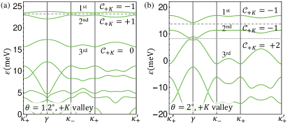
Beyond a critical angle the gap between the second and the third bands closes at the point, as illustrated in Fig. 4. When crosses from below, the Chern number of the first band in valley remains as , while the Chern numbers for the second and third bands change from to . Although, the two-orbital model (7) is not fully applicable for it still captures the main character of the first two bands in regions of momentum space away from the point. The system remains as a topological insulator when the chemical potential is in the gap between the first and the second bands until reaches , beyond which there is no global gap between the first two bands. In the SMSM , we have verified the robustness of our predicted topological bands against perturbation from remote bands.
Field induced topological transition.— Because the two sublattices in (7) are associated with different layers, a vertical electric field generates a staggered sublattice potential, which can induce a topological phase transition Haldane (1988); Kane and Mele (2005a, b). To study this transition, we add a layer dependent potential to the moiré Hamiltonian (4) so that . (We neglect the small spatial modulation of due to variation in the vertical distance between layers in the moiré pattern Zhang et al. (2017).) The magnitude of has a critical value , at which the gap between the first and the second moiré bands closes at points. When , wave functions in the first moiré band are primarily localized in one single layer and the band becomes topologically trivial. The tight-binding model (7) predicts that is equal to splitting between the first and the second bands at when , because the interlayer hopping term in (7) vanishes at these momenta. In Fig. 4(c) we compare values of calculated from the tight-binding and the full moiré band Hamiltonian, showing that they match well, particularly for small twist angles (long moiré period). We note that there is no one-to-one correspondence between the Chern numbers of the electronic bands and the winding number of the pseudospin field, which remains non-trivial until equals evaluated at the or sites.
Interaction effects.— When the moiré bands are nearly flat, the density of states is strongly enhanced [Fig. 3(b)] and many-body interaction effects are magnified. Here we focus on interaction effects within the first two moiré bands at zero and small . The on-site Coulomb repulsion scales as , where is an effective dielectric constant that depends on the three-dimensional dielectric environment, and is the spatial extent of the Wannier orbitals centered at or sites. For around , we find that can be more than one order of magnitude larger than the hopping parameters SM . In the strong correlation limit, we anticipate that the interplay between layer and spin/valley degrees of freedom will lead to unusual distinct insulating states at integer numbers of holes per MUC. For one hole per MUC, where the first moiré band is half filled, one candidate insulating state is ferromagnetic. Because the single-particle Hamiltonian has only symmetry, perpendicular spin polarization is energetically preferred. The Ising spin anisotropy implies finite temperature phase transitions. When the first moiré band is completely spin-polarized, the system is a quantum anomalous Hall insulator. Similar physics could occur for three holes per MUC, where the second moiré band is half filled. For two holes per MUC (equivalently one hole per sublattice site of the honeycomb lattice in Kane-Mele model), there is a competition between the quantum spin Hall insulator and the antiferromagnetic insulator Hohenadler et al. (2011), which occur for weak and strong interactions respectively. For some fractional numbers of holes per MUC, the flat bands may host fractional topological insulators Qi (2011).
Discussion.— It has been proposed that Hubbard model can be simulated in TMD heterobilayers Wu et al. (2018a). In twisted TMD homobilayers, the two layers can be effectively decoupled by using a finite layer bias potential to drive the system into region (II) of the phase diagram in Fig. 4(c). Thus, conventional one-orbital Hubbard model can also be studied in twisted homobilayers, with a greater scope for in situ manipulation of model parameters. Compared to heterobilayers, twisted TMD homobilayers may be experimentally realized with a more precise control of the twist angle by using the ‘tear-and-stack’ techniqueKim et al. (2017); Cao et al. (2018a, b). In the SM SM , we also show that a two-orbital Hubbard model can be simulated using twisted TMD homobilayers in the AB stacking configuration. Moiré bands with valley-contrasting Chern numbers have been proposed in some graphene-based moiré systems Song et al. (2015); Zhang et al. (2018); Chittari et al. (2019). In this case however, quantum spin Hall states that might be induced by interactions cannot survive to accessible temperatures because electrons in graphene have accurate spin symmetry which enhances fluctuation effects. In Ref. Tong et al. (2017), quantum spin Hall nano-dots and nano-stripes have been proposed for TMD-based moiré systems in which the large gap between valence and conduction bands needs to be inverted by strong vertical electric field. In contrast, our model Hamiltonian relies only on valence band states. Our proposal for topological states is based on valley contrast physics and on pseudospin texture in the moiré pattern; the advantage is that it does not require massless chiral fermions in the parent monolayer or aligned bilayer, which may lead to application in a larger class of two-dimensional materials.
F.W. and I.M. are supported by the Department of Energy, Office of Science, Materials Science and Engineering Division. F.W. is also supported by Laboratory for Physical Sciences. Work at Austin is supported by Army Research Office (ARO) Grant W911NF-17-1-0312 (MURI) and by the Welch foundation under Grant TBF1473. We acknowledge HPC resources provided by the Texas Advanced Computing Center (TACC) at The University of Texas at Austin.
References
- Hunt et al. (2013) B. Hunt, J. D. Sanchez-Yamagishi, A. F. Young, M. Yankowitz, B. J. LeRoy, K. Watanabe, T. Taniguchi, P. Moon, M. Koshino, P. Jarillo-Herrero, and R. C. Ashoori, Science 340, 1427 (2013).
- Dean et al. (2013) C. R. Dean, L. Wang, P. Maher, C. Forsythe, F. Ghahari, Y. Gao, J. Katoch, M. Ishigami, P. Moon, M. Koshino, T. Taniguchi, K. Watanabe, K. L. Shepard, J. Hone, and P. Kim, Nature 497, 598 (2013).
- Wang et al. (2015) L. Wang, Y. Gao, B. Wen, Z. Han, T. Taniguchi, K. Watanabe, M. Koshino, J. Hone, and C. R. Dean, Science 350, 1231 (2015).
- Kim et al. (2017) K. Kim, A. DaSilva, S. Huang, B. Fallahazad, S. Larentis, T. Taniguchi, K. Watanabe, B. J. LeRoy, A. H. MacDonald, and E. Tutuc, Proc. Natl. Acad. Sci. U.S.A. 114, 3364 (2017).
- Spanton et al. (2018) E. M. Spanton, A. A. Zibrov, H. Zhou, T. Taniguchi, K. Watanabe, M. P. Zaletel, and A. F. Young, Science 360, 62 (2018).
- Chen et al. (2018) G. Chen, L. Jiang, S. Wu, B. Lv, H. Li, K. Watanabe, T. Taniguchi, Z. Shi, Y. Zhang, and F. Wang, arXiv:1803.01985 (2018).
- Bistritzer and MacDonald (2011) R. Bistritzer and A. H. MacDonald, Proc. Natl. Acad. Sci. U.S.A. 108, 12233 (2011).
- Cao et al. (2018a) Y. Cao, V. Fatemi, A. Demir, S. Fang, S. L. Tomarken, J. Y. Luo, J. D. Sanchez-Yamagishi, K. Watanabe, T. Taniguchi, E. Kaxiras, R. C. Ashoori, and P. Jarillo-Herrero, Nature 556, 80 (2018a).
- Cao et al. (2018b) Y. Cao, V. Fatemi, S. Fang, K. Watanabe, T. Taniguchi, E. Kaxiras, and P. Jarillo-Herrero, Nature 556, 43 (2018b).
- Wu et al. (2018a) F. Wu, T. Lovorn, E. Tutuc, and A. H. MacDonald, Phys. Rev. Lett. 121, 026402 (2018a).
- Po et al. (2018) H. C. Po, L. Zou, A. Vishwanath, and T. Senthil, Phys. Rev. X 8, 031089 (2018).
- Wu et al. (2018b) F. Wu, A. H. MacDonald, and I. Martin, Phys. Rev. Lett. 121, 257001 (2018b).
- Naik and Jain (2018) M. H. Naik and M. Jain, Phys. Rev. Lett. 121, 266401 (2018).
- Chittari et al. (2019) B. L. Chittari, G. Chen, Y. Zhang, F. Wang, and J. Jung, Phys. Rev. Lett. 122, 016401 (2019).
- Zhang et al. (2018) Y.-H. Zhang, D. Mao, Y. Cao, P. Jarillo-Herrero, and T. Senthil, arXiv:1805.08232 (2018).
- Xiao et al. (2012) D. Xiao, G.-B. Liu, W. Feng, X. Xu, and W. Yao, Phys. Rev. Lett. 108, 196802 (2012).
- (17) See Supplemental Material at URL for ab initio band structure, perturbations from remote bands, additional discussion of interaction effects, and simulation of two-orbtial Hubbard model using the AB stacking configuration, which includes Ref. Liu et al. (2013); Agarwal and Capers (1972); Wang et al. (2017) .
- Jung et al. (2014) J. Jung, A. Raoux, Z. Qiao, and A. H. MacDonald, Phys. Rev. B 89, 205414 (2014).
- Giannozzi et al. (2009) P. Giannozzi et al., J. Phys.: Condens. Matter 21, 395502 (2009).
- Wu et al. (2018c) F. Wu, T. Lovorn, and A. H. MacDonald, Phys. Rev. B 97, 035306 (2018c).
- Wu et al. (2017) F. Wu, T. Lovorn, and A. H. MacDonald, Phys. Rev. Lett. 118, 147401 (2017).
- Moon et al. (1995) K. Moon, H. Mori, K. Yang, S. M. Girvin, A. H. MacDonald, L. Zheng, D. Yoshioka, and S.-C. Zhang, Phys. Rev. B 51, 5138 (1995).
- Nagaosa and Tokura (2013) N. Nagaosa and Y. Tokura, Nature Nanotechnology 8, 899 (2013).
- Xiao et al. (2010) D. Xiao, M.-C. Chang, and Q. Niu, Rev. Mod. Phys. 82, 1959 (2010).
- Kane and Mele (2005a) C. L. Kane and E. J. Mele, Phys. Rev. Lett. 95, 226801 (2005a).
- Kane and Mele (2005b) C. L. Kane and E. J. Mele, Phys. Rev. Lett. 95, 146802 (2005b).
- Haldane (1988) F. D. M. Haldane, Phys. Rev. Lett. 61, 2015 (1988).
- Zhang et al. (2017) C. Zhang, C.-P. Chuu, X. Ren, M.-Y. Li, L.-J. Li, C. Jin, M.-Y. Chou, and C.-K. Shih, Sci. Adv. 3, e1601459 (2017).
- Hohenadler et al. (2011) M. Hohenadler, T. C. Lang, and F. F. Assaad, Phys. Rev. Lett. 106, 100403 (2011).
- Qi (2011) X.-L. Qi, Phys. Rev. Lett. 107, 126803 (2011).
- Song et al. (2015) J. C. W. Song, P. Samutpraphoot, and L. S. Levitov, Proc. Natl. Acad. Sci. U.S.A. 112, 10879 (2015).
- Tong et al. (2017) Q. Tong, H. Yu, Q. Zhu, Y. Wang, X. Xu, and W. Yao, Nat. Phys. 13, 356 (2017).
- Liu et al. (2013) G.-B. Liu, W.-Y. Shan, Y. Yao, W. Yao, and D. Xiao, Phys. Rev. B 88, 085433 (2013).
- Agarwal and Capers (1972) M. K. Agarwal and M. J. Capers, J. Appl. Cryst. 5, 63 (1972).
- Wang et al. (2017) Y. Wang, Z. Wang, W. Yao, G.-B. Liu, and H. Yu, Phys. Rev. B 95, 115429 (2017).
Supplemental Material
This Supplemental Material includes the following five sections: (1)DFT band structure, (2) a four-band model with remote conduction bands, (3) a four-band model with remote spin-split valence bands, (4) interaction effects in the Kane-Mele model, and (5) simulation of two-orbtial Hubbard model using the AB stacking configuration where the two layers are relatively rotated by an angle near .
I DFT band structure
We perform fully-relativistic density functional theory (DFT) calculations under the local density approximation (LDA) for aligned MoTe2 bilayers using Quantum Espresso Giannozzi et al. (2009). The Perdew-Zunger (LDA) exchange-correlation functional has been used. We choose a plane-wave cutoff energy of 50 Ry and a corresponding charge density cutoff energy of 408 Ry, and we sample the Brillouin zone with a 16161 grid of points. The thickness of the vacuum layer is about 20 Å. The in-plane lattice constant is taken to be 3.472 Å.Liu et al. (2013); Agarwal and Capers (1972) The in-plane atomic positions are fixed, while the out-of-plane positions have been relaxed for all atoms until the out-of-plane direction force on each atom is less than 0.005 eV/Å.
The band structures for AA stacked MoTe2 bilayers () are shown in Figs. 5(a, b) respectively for in-plane displacements and . We note that bilayers with displacements and are related by a mirror operation ; therefore the two structures have identical energy dispersion, while the wave function characters are related by the mirror operation. We measure the layer separation by the vertical distance between the metal (Mo) atoms associated with different layers. With this definition, is respectively 7.8Å and 6.9Å for and structures.
As shown in Fig. 5, the valence band maxima are located in valleys for both and structures. Therefore, in our model study, the topmost moiré valence states are derived from valleys. This is the reason why we choose MoTe2 bilayers, whereas in other TMDs, for example MoS2 bilayers Naik and Jain (2018), the valence band maximum is located in valley. Because the valence band maximum at the point is only lower in energy compared to that at points by about 80 meV in the structure of MoTe2, the DFT calculation may not be accurate enough to precisely determine the energy separation between and valence states. However, the and states are always separated by a large momentum, and therefore, they can be studied separately in a low-energy theory.
To determine the orbital, layer and spin characters of the bands, we obtain a tight-binding Hamiltonian in a basis of Wannier functions using Wannier90. We project onto orbitals of Te and orbitals of Mo without performing maximal localization, and reproduce the DFT band structure with high accuracy.
We have also performed DFT study for AA stacked WSe2 bilayer, of which the valence band maxima are located at points for structure, but at point for structures, according to our calculation. Because of this complicated energy landscape, it should be examined experimentally whether low-energy moiré bands in twisted bilayer WSe2 are derived from valleys or valley. More advanced band structure calculation, such as GW calculation, should also be applied to bilayer WSe2 to get a more accurate estimation of the energy landscape. The effective model in Eq.(2) of the main text applies equally to valley moiré valence states in twisted bilayer WSe2 (other TMDs as well); the corresponding parameter values for WSe2 are (8.9 meV, , meV), and there are similar topological moiré bands.
II Remote conduction bands
In monolayer TMDs, the Hamiltonian at valleys is often described by a massive Dirac model in the basis of conduction and valence band sates Xiao et al. (2012). This massive Dirac model is particularly convenient for analyses of the valley dependent optical selection rules. In the main text, we have discarded the conduction band states and used a parabolic band approximation for valence band states. There is a question about whether such an approximation is adequate to capture all important low-energy physics, in particular the moiré band structure and the topological character. Below we answer this question in the affirmative by studying a moiré Hamiltonian that includes both the valence and conduction bands.
As in the main text, we study spin up states at valley. For aligned bilayers, the Hamiltonian that includes both conduction and valence band states is given by:
| (8) |
where is the massive Dirac Hamiltonian in layer , and is the interlayer tunneling matrix. is given by:
| (9) |
Here the two components refer to the metal and orbital states, which carry different angular momenta and represent the main character respectively for conduction () and valence () band states. In (9), is the average band gap, is the variation of band extrema energy as a function of , and is the Fermi velocity. Here is the band index for and . Similar to Eq.(2) in the main text, can be parametrized as:
| (10) |
The tunneling matrix is derived by using a two-center approximation Bistritzer and MacDonald (2011) and also taking into account the threefold-rotational symmetry at high-symmetry displacements Wang et al. (2017). is parametrized as:
| (11) | ||||
The mirror operation () leads to the constraints that and are real numbers, and . Note that the interlayer tunneling between valence and conduction band states vanishes at .
We determine parameter values by fitting to the first-principles band structure at the three high-symmetry displacements. For stacked MoTe2 bilayer, we obtain that eV, m/s, (8 meV,, meV), (5.97 meV, , meV) and meV. Here and are close to , which implies that the scalar potential has an amplitude much smaller than that of the potential difference . We note that density-functional theory underestimates the band gap , but the exact numerical values should not influence qualitative effects that we discuss.
The band gap is much larger than other energy scales. Therefore, we can integrate out conduction band states using a second-order perturbation theory, and the resulting model is exactly that in Eq. (1) of the main text. The effective mass is then approximated by , and the spatial modulation of is of order and can be neglected. In the main text, has been used where is the electron bare mass. This provides the first justification that the model with only valence band states is valid.
We continue with the four-band Hamiltonian (8). When there is a twist between the two layers, the moiré Hamiltonian is:
| (12) |
where is the two-dimensional position operator. in the moiré pattern has the form
| (13) | ||||
where is the Pauli matrix in the band basis. The moiré potentials and the tunneling term are obtained from Eqs. (10)-(11) by replacing with . The moiré Hamiltonian (12) is formally similar to that for twisted bilayer graphene Bistritzer and MacDonald (2011); Wu et al. (2018b), and the main differences are the Dirac mass .
We diagonalize the moiré Hamiltonian (12) by using a plane-wave expansion and parameter values of MoTe2 bilayer. The moiré bands and the Chern numbers are summarized in Fig. 6. The moiré valence bands and the Chern numbers are consistent with those obtained using the two-band model of the main text. Fig. 6(b) shows the two lowest-energy moiré conduction bands in spin up sector at valley, which carry Chern numbers . The topological character of the moiré conduction bands can be understood in the same way as that for valence bands.
In monolayer TMD, the valence band edges at valley already carry a finite Berry curvature due to the absence of inversion symmetry Xiao et al. (2012), and the corresponding Berry curvature at point is given by , which is about 0.113 nm2 for monolayer MoTe2. In contrast, the typical value of the Berry curvature as shown in Fig. 3 of the main text for the topological moiré band is about nm2, three orders of magnitude larger than the intrinsic monolayer value. We can define a dimensionless quantity , which is much smaller than 1 and justifies the two-band model with only valence band sates.
III Remote valence bands
We study spin mixing effects from remote valence bands. In TMDs, the topmost spin up and down valence bands at points are separated in energy by more than 100 meV. In monolayer TMDs, the mirror symmetry can be used to classify the bands into two mirror sectors, and the spin-mixing effects are typically ignored. In bilayer TMDs, this mirror symmetry is generally broken.
Here we study valence bands at valley, including spin-orbit split bands. For aligned bilayers, the Hamiltonian is given by:
| (14) |
Here is the intra-layer Hamiltonian given by:
| (15) |
where the two components refer to spin up and down valence states at valley . Here we use up and down to refer to the major spin character. In (15), the off-diagonal spin-mixing terms are approximated as zero because these terms vanish at the three high-symmetry displacements due to the three-fold rotational symmetry. is the spin splitting, and the variation energy is parametrized as:
| (16) |
The interlayer tunneling does include symmetry-allowed spin-mixing terms:
| (17) | ||||
The mirror operation (), which maps to , implies that and are real, and , because the mirror operation acts as in the spin space and in the layer space. Note that this mirror operation is not a symmetry for a generic expect at .
We again determine the parameter values by fitting to the first-principles band structure, and obtain that meV, (8 meV,, meV), (7.7 meV, , meV) and meV.
We map the Hamiltonian in (14) to the moiré Hamiltonian at a finite twist angle. The calculated moiré band structure are shown in Fig. 7, which are nearly identical to that obtained in the main text. This is expected because the spin mixing terms are at least an order of magnitude smaller compared to the spin-orbit splitting .
In conclusion, the two-band model given in Eq. (1) of the main text provides a faithful low-energy description of moiré valence bands at small twist angles. We have used quantum spin Hall insulator as a synonym of two-dimensional topological insulator Kane and Mele (2005b), which is a distinct phase without requirement of spin conservation.
In our theory, spin, strictly speaking, is not a good quantum number, but valley is a good quantum number and plays the role of an effective spin. Therefore, the invariant of the quantum spin Hall insulator and the valley Chern number are directly connected. We can denote the Chern number for bands below a chemical potential in valley as , where is or for the two valleys. Because of time-reversal symmetry, . The invariant is given by . Based on this definition, the system is in the quantum spin Hall insulator phase (two-dimensional time-reversal-invariant topological insulator) in region (I) of Fig. 4(c) [main text] when the chemical potential is in the gap between the first and the second moiré bands.
IV Kane-Mele-Hubbard model
We provide additional discussion of many-body interactions in the topological moiré bands. As in the main text, we focus on interaction effects within the first two moiré bands with small twist angle, where the tight-binding model is applicable.
The interaction strength can be tuned by the three-dimensional dielectric environment, and the range of interaction can be controlled by a nearby metallic gate. Here we only consider the on-site repulsive interaction and assume that longer-range interactions are suppressed due to the nearby gate. Effects of long-range Coulomb interaction on the topological bands are also interesting, which we leave to future exploration. scales as , where is the effective dielectric constant. is the spatial extent of the Wannier orbitals, which can be estimated based on a harmonic oscillator potential approximation of the moiré potential near one of its maximum position Wu et al. (2018a). At , is about 3 nm; for comparison, the corresponding moiré period is 16.6 nm. If we take to be 10, then meV, which is two orders of magnitude larger than the hopping parameter meV at . Therefore, the ratio , which depends on the dielectric environment and the twist angle, can be much greater than one.
By combining the tight-binding model and the on-site interaction, we arrive at the Kane-Mele-Hubbard model:
| (18) |
The tight-binding model is given by:
| (19) | ||||
where and are Pauli matrices in the sublattice and spin spaces, and are functions of the momentum . The tight binding model has two energy branches and each branch is doubly degenerate. The term is not important for the topological properties and is absent in the original Kane-Mele model of Refs. Kane and Mele (2005a, b). At the filling factor where there are two electrons per unit cell (equivalent to one electron per sublattice site), there is a competition between the quantum spin Hall insulator and the antiferromagnetic Mott insulator in the Kane-Mele-Hubbard model Hohenadler et al. (2011). Here we focus on a different filling factor where there are three electrons (equivalent to one hole) per unit cell. At this filling factor, the upper two bands are half filled in the non-interacting limit. Because the upper two bands carry spin contrast Chern numbers, the isolated upper band in either spin sector does not have exponentially localized Wannier states. These nearly flat topological bands are similar to Landau levels which are completely flat but have no exponentially localized Wannier states. It is well established that Landau levels with internal degeneracies (for example spin) develop ferromagnetism when they are partially filled with an integer number of electrons per cyclotron orbit. By making an analogy to the Landau level problems, we anticipate that ferromagnetism is likely at the filling factor of one hole per moiré unit cell.
We now use a mean-field theory to demonstrate the Ising anisotropy in the ferromagnetic state. We perform a Hartree-Fock approximation for the Hubbard interaction on each site:
| (20) |
where and . Here represents the mean-field average value, and . The full mean-field Hamiltonian is:
| (21) | ||||
where , and is the number of unit cells. generally has four non-degenerate energy bands. We consider zero temperature, and assume that the magnetization is strong enough such that the highest energy band is completely empty and other three bands are fully occupied by electrons. The total energy is then given by:
| (22) | ||||
where , , and the vector is parametrized by the spherical coordinates . The saddle point equation correctly reproduces the self-consistent equation . The energy functional is independent of the azimuthal angle , which is a result of the spin symmetry of the Hamiltonian (18). does depend on the polar angle , and is minimized by placing along axis. Thus, there is an Ising anisotropy that favors the out-of-plane spin polarization.
V AB stacking configuration
In TMD bilayers with long period moiré pattern, there is another distinct stacking configuration that we label as AB Wu et al. (2018c). AA and AB stacking, which are sometimes respectively referred to as and stacking, are distinguished by a 180∘ rotation of the top layer. Below we discuss valley moiré bands in the AB stacking configuration.
In AB stacking with zero twist angle and an arbitrary in-plane displacement , there is always an inversion symmetry , and the inversion center is at the midpoint between the two shifted metal atoms located in different layers Wang et al. (2017), as illustrated in Fig. 8. The combined symmetry enforces a double degeneracy of the band structure at every momentum. We again focus on valley, and electronic properties at valley can be inferred by using the symmetry. At valley, the topmost valence bands associated with the bottom and top layer respectively have spin up and down characters, and they are degenerate due to the symmetry, leading to the following Hamiltonian:
| (23) |
where the two components refer to bottom (spin up) and top (spin down) layers, is the variation of the valence band maximum energy as a function of , and the Hamiltonian is proportional to an identity matrix in the layer pseudospin space because of the the symmetry. In this low-energy Hamiltonian (23), the two layers are effectively decoupled.
In twisted bilayer, we obtain the moiré Hamiltonian by replacing with and taking into account the momentum shift between the two layers:
| (24) |
where the two layers are again effectively decoupled and can be studied separately in the single particle Hamiltonian, and the momentum shift can therefore be removed by a layer-dependent gauge transformation. In each layer electrons move in the layer-independent potential and form moiré bands that are topologically trivial. The topmost moiré valence bands can be used to simulate the Hubbard model on a triangular lattice with two orbitals that are centered in different layers but at the same in-plane positions. This two-orbital Hubbard model has an approximate symmetry, which would become exact if the vertical separation between the two orbitals were neglected. We will report a detailed study of this two-orbital Hubbard model in a separate work. A vertical electric field generates an energy difference between the two orbitals, and can lead to the realization of the conventional single-orbital Hubbard model when the field is strong enough Wu et al. (2018a).