©2018 IEEE. Personal use of this material is permitted. Permission from IEEE must be obtained
for all other uses, in any current or future media, including reprinting/republishing this material
for advertising or promotional purposes, creating new collective works, for resale or redistribution
to servers or lists, or reuse of any copyrighted component of this work in other works.
Pre-print of article that will appear in the 2018 IEEE International Symposium on Safety, Security and Rescue Robotics (SSRR).
Please cite this paper as:
A. Gawel, Y. Lin, T. Koutros, R. Siegwart, and C. Cadena. (2018).
"Aerial-Ground collaborative sensing: Third-Person view for teleoperation" in IEEE International Symposium on Safety, Security and Rescue Robotics (SSRR), 2018.
bibtex:
@inproceedings{gawel2018aerial,
title={Aerial-Ground collaborative sensing: Third-Person view for teleoperation},
author={Gawel, Abel and Lin, Yukai and Koutros, Theodore and Siegwart, Roland and Cadena, Cesar},
booktitle=Safety, Security and Rescue Robotics (SSRR), IEEE International Symposium on},
year={2018}
}
Aerial-Ground collaborative sensing: Third-Person view for teleoperation
Abstract
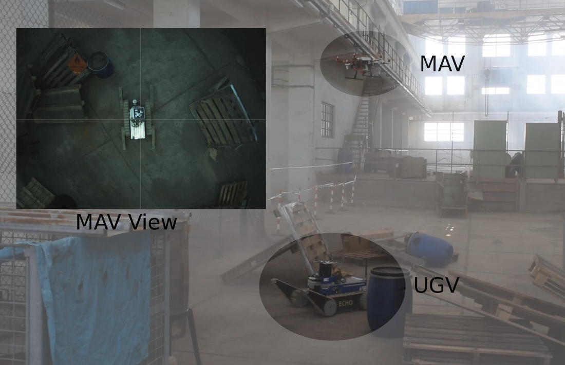
Rapid deployment and operation are key requirements in time critical application, such as Search and Rescue (SaR). Efficiently teleoperated ground robots can support first-responders in such situations. However, first-person view teleoperation is sub-optimal in difficult terrains, while a third-person perspective can drastically increase teleoperation performance. Here, we propose a Micro Aerial Vehicle (MAV)-based system that can autonomously provide third-person perspective to ground robots. While our approach is based on local visual servoing, it further leverages the global localization of several ground robots to seamlessly transfer between these ground robots in GPS-denied environments. Therewith one MAV can support multiple ground robots on a demand basis. Furthermore, our system enables different visual detection regimes, and enhanced operability, and return-home functionality. We evaluate our system in real-world SaR scenarios.
I Introduction
Effective teleoperation is a key requirement for many contemporary Unmanned Ground Vehicle (UGV) systems. Usually, these systems are teleoperated in a first-person perspective, using on-board cameras and further sensors of the robots. While this is sufficient in easy terrain, the teleoperation task can become cumbersome in challenging terrains, where narrow passages or obstacles need to be traversed. In these situation not only the overall progress of a mission can be compromised but also the integrity of the vehicle in use.
MAVs on the other hand offer rapid speeds and a higher point of view, giving them superior performance as flying cameras. However, often it is not sufficient to use MAVs alone in such scenarios as their operation times and payload are typically more constrained than of UGVs. Here, UGVs can complement the MAV capabilities with manipulators, and further sensors for close interaction with the environment.
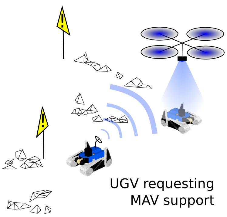
Therefore, the combination of the individual robots’ strengths in an integrated system can be a fruitful avenue [1, 2, 3, 4]. Recent works have shown that a third-person perspective can prove efficient to support robot operators in such scenarios [1, 5], e.g., by using MAVs as flying cameras. Unfortunately, these systems are limited to off-board computations, structured and well illuminated scenarios, single-UGV support, tag-based detection [6], and local-following only. Here, we extend our prior work [4] and propose an automatic system based on a MAV that can overcome these limitations and support multiple UGVs in difficult teleoperation tasks. In our system, the MAV serves as a flying camera that can autonomously follow a UGV and provide a third-person view, as illustrated in Fig. 1.
Our system is designed to operate in GPS-denied environments, and therefore we assume no external localization system. Therefore, the MAV localization is loosely coupled with the UGV localization, and can therewith support multiple UGVs. The MAV interfaces with the LiDAR-based global localization of the UGVs allowing for traveling among them on a demand basis. Visual-inertial sensing onboard the MAV allows it to navigate between multiple UGVs and assist teleoperation. Our system operates fully autonomous, freeing operators from the need to separately control the flying camera. The system has been tested in real-word experiments in challenging indoor SaR scenarios. To the best of our knowledge, this is the first system to integrate all these functionalities.
This paper presents the following contributions:
-
•
A system for relative localization, visual servoing, and control of MAV for third-person view teleoperation.
-
•
Feature-based detection of different UGV types.
- •
-
•
Experimental evaluation in challenging real-world SaR scenarios.
This paper is organized as follows; In Section II, we review the state of the art on MAV-UGV collaboration, visual servoing, and third-person view teleoperation. Section III describes our integrated system, and its evaluation is presented in Section IV. Finally, we conclude our findings in Section V.
II Related work
The topic of MAV-UGV cooperation has received increasing attention in the last decade with the advent of affordable MAVs and increased onboard processing power [7, 5, 1, 2, 3]. Many contemporary works focus on enhancing the UGV’s perception using MAVs [5, 8, 9, 1, 10, 2, 3, 11, 12]. A related functionality is to use MAVs for interaction, e.g., object picking and transportation [13, 4, 14]. Typically, the UGV and the MAV need to be co-localized and controlled in a shared reference frame [15]. This is commonly solved using visual servoing, i.e., visual detection between the robots and applying a suitable control regime [16].
The detection in visual servoing systems, is often based on special markers [5, 8, 7, 9, 1], simple visual color blob detection [4, 14, 11], or visual feature-based detection [17]. Special markers, e.g., Apriltags [6], are a well established technique for robust visual-marker detection, and have superseded LED-based detection in recent years [8]. In more general visual servoing cases, the UGV cannot be augmented with specific markers. Hence, visual detection is still needed in such cases.
Another option is to localize the robots in a common map without direct detection [12, 2, 3]. Here, both robots are equipped with additional LiDAR, or camera sensors for precise localization and collaborative mapping. However, Michael et al. [12] state that additional direct detection between the robots would be desirable for direct collaboration.
The control for visual servoing is mainly on trajectory or waypoint tracking. In recent years, the control problem for MAVs has been intensively investigated. A classic PID controller performs better than an LQ controller due to the model imperfections [18]. A nonlinear tracking controller often used is shown to have desirable closed loop properties with global stability [19]. To exert state and input constraints, Model Predictive Controller (MPC) has been introduced and employed to control the MAV, and it was further shown that Nonlinear MPC performs better than linear MPC in disturbance rejection and tracking performance [20].
Multiple works have shown that a third-person view can prove useful in teleoperation tasks [1, 21, 22]. While [21] use 3D maps as they could be build from on-board sensing of the UGV, [22] show the use of a MAV as an external camera for assisted manipulation. However, [22] focus on a static target, and [21] require additional 3D sensing on the UGV to render a third-person view from the local sensing. The most similar work to ours is [1]. Here, the authors focus on evaluating the assisted teleoperation by a MAV-based system in SaR scenarios. While the system integration and development has been simplified and limited in order to perform the user-studies. Some of those are off-board computing, single-UGV support, and simplified environmental conditions.
Cooperation between multiple UGVs and Unmanned Aerial Vehicle (UAV)s has been researched in the last decades. An early work of [23] studies the cooperation of two UGVs and one aerial robot regarding localization of the aerial robot by visually communicating and locating with the ground robot. Hsieh et al. [24] demonstrated multi-agent tasking and provided cooperative control strategies for search, identification, and localization of targets. The survey of [25] identifies several open problems on UGV/UAV cooperation including vehicle autonomy, and integrated control.
This paper focuses on lifting simplifications of the current state of the art by extending our previous work on MAV object detection and picking [4, 14], adding dedicated multi-UGV support, and visual-feature based object detection for MAV-assisted teleoperation. We use state of the art Nonlinear MPC on the MAV. Furthermore, we demonstrate the system in perceptually difficult indoor SaR scenarios and perform computations on-board the MAV which ensures safe operation in case of network failures.
III Third-person View Teleoperation
Here, we present our MAV assisted third-person view system for UGV teleoperation. The system is based on object detection, visual servoing, Visual Inertial Odometry (VIO), and interfacing with the UGVs’ global localization to operate in GPS-denied environments. A system overview is depicted in Fig. 2.
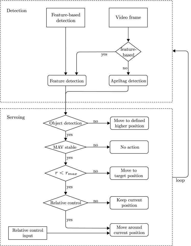
As illustrated in the upper part of Fig. 2, the detector uses either tag-based detection [6], or visual feature-based object detection, based on an initially captured image of the UGV [26].The detections are then sent to the visual servoing, which computes the MAV’s relative, and target poses, and applies the necessary control to the MAV for hovering above the UGV. Finally, upon successful relative localization of the MAV with respect to the UGV, the global frames of UGV and VIO are aligned for global localization of the MAV, and enabling transfer among multiple UGVs.
III-A Visual Servoing
The servoing strategy is agnostic to the used detection regime. Either the pose of the detected tag, or the pose of the smallest quadrilateral box containing the target object when using feature-based UGV detection are forwarded to the visual servoing algorithm. We represent transformations in SE3, consisting of position , and orientation in roll , pitch , and, yaw in quaternion form. The algorithm first estimates the relative pose between MAV and UGV in the camera frame .
Here, we only consider rotations in yaw. Rotations in pitch and roll are assumed negligible, since the MAV can only remain stable when it is stationary hovering over the UGV, and takes actions only in static hovering mode.
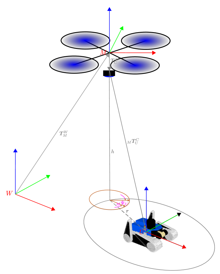
Besides relative localization, the MAV also localizes itself in the world using VIO, as implemented in [27]. The position controller receives commands in world coordinates. We therefore need to apply a transformation chain to the relative localization. The MAV’s pose is represented in the world frame . Thus, is then transformed into the world frame, using the VIO estimate , and the extrinsic calibration between MAV IMU and camera , forming the relative transformation between MAV and UGV in world coordinates, i.e.,
| (1) |
This is also illustrated in Fig. 3.
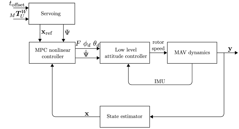
The localization result is then sent to an MPC [28] for position control. Here, the MPC acts to keep the MAV within a circle of radius in a height above the center of the UGV, and identical yaw orientation, i.e., . Furthermore, a user-controllable offset translation in UGV body coordinates can be added. The controller structure is shown in Fig. 4. The position command is handled by the MPC nonlinear controller to generate desired motion control. The optimization problem for the MPC is formulated as
| (2) |
in the time interval . Here, is the penalty on the state error, is the penalty on control input error and P is the terminal state error. The state vector represents the position, velocity, roll and pitch angle of the MAV and input vector consists of control input of roll, pitch angle and thrust force . The desired state and steady state input are denoted as and . Finally, the result is sent to a low level attitude controller to generate desired rotor speed control.
III-B Multi-UGV support
In our system, the UGVs are performing LiDAR-based 3D SLAM [29], enabling them to globally localize in a common frame. The SLAM system operates on a pose-graph basis, registering ICP LiDAR scan alignments, and odometry. Furthermore, open-loop drift is compensated upon loop-closures using ICP and a low drift assumption.
Upon start, we initialize all robots, including MAV in the origin of the world frame, yielding a shared reference frame. This common frame is maintained via LiDAR-based SLAM for the UGVs, i.e., estimating their pose and VIO for the MAV . The knowledge of the poses of UGVs in the world frame allow us to calculate the relative transform between two UGVs and . This enables robot-to-robot third-person-view transfers. Passed to the controller of the MAV, the MAV can transfer between multiple UGVs, before switching back to visual servoing.
One important characteristic of this hybrid system is different drift characteristics in the LiDAR-based localization and the VIO for UGV and MAV, respectively. In our system, we give higher confidence in the accuracy of LiDAR-based localization and therefore reset on transition events towards the UGV estimate, i.e.,
| (3) |
The relative drift between VIO and LiDAR-based SLAM are then compensated through the visual servoing.
The return-home functionality is realised with the same detection regime. When the MAV concludes its mission, the operator can request it to return from visual servoing above a UGV to a home position in the world frame, e.g., the starting point. The MAV will thus return to the home position using VIO and descend to the ground. If high accuracy is required upon landing, the home position can be equipped with a visual tag, such that the visual servoing will correct for odometry drift before landing.
IV Experiments
We evaluate our system in two different indoor experiments and record its performance. Our evaluation focuses on the visual servoing performance and the proposed multi-UGV interface and transfer with the MAV. We furthermore demonstrate the effectiveness of the third-person teleoperation in a realistic industrial SaR scenario. The benefits of third-person view teleoperation has been extensively evaluated and concluded in [1, 21, 22], and further evaluations are therefore outside the scope of this paper.
IV-A Experimental setup
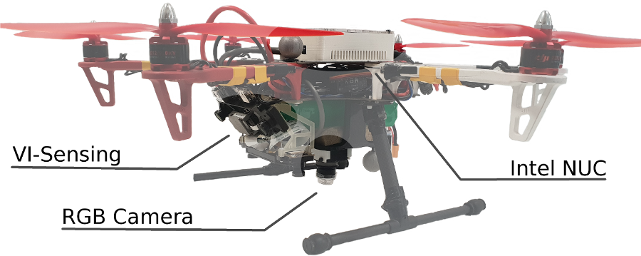
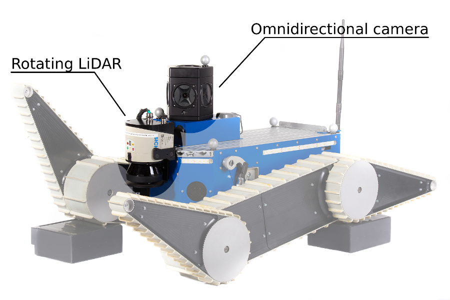
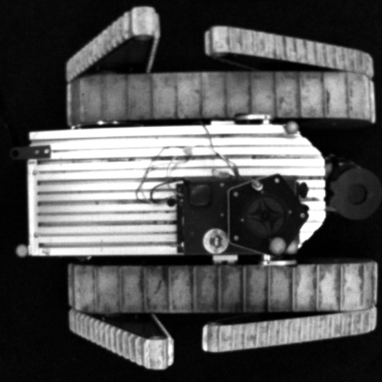
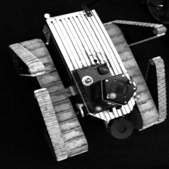
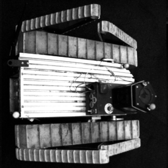
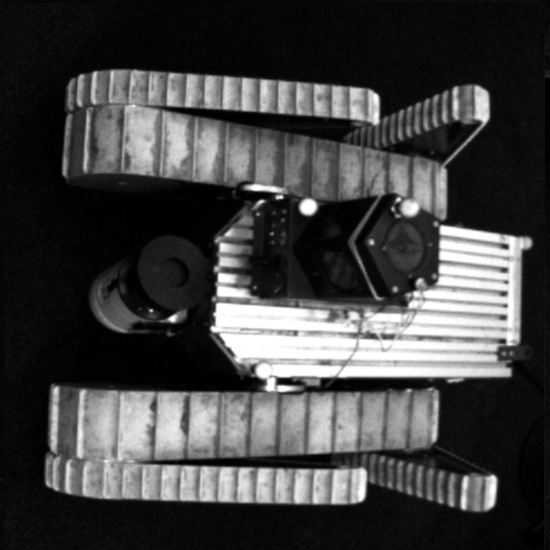
The MAV used in our experiments is a custom build hexacopter based on the DJI Flamewheel F550, and illustrated in Fig. 5(c). It is equipped with a downward facing Chameleon 3 camera with a resolution of 3.2 Megapixels @ which is used both for the visual servoing and providing the third-person view111For the tag-based, and the feature-based detection, we use the implementations from https://github.com/RIVeR-Lab/apriltags_ros and https://github.com/introlab/find-object respectively.. Furthermore, it is equipped with a variable set of one or two stereo-vision pairs integrated with an IMU for VIO. The stereo pairs are mounted 45∘ and 90∘ with respect to the horizontal. All processing is done onboard the MAV on an Intel Core i7-7567U CPU @ . The flight time of the MAV with an initially fully charged battery is approximately minutes. The UGV used for the LiDAR-based mapping is a tracked vehicle, equipped with encoders, IMU, and a sweeping LiDAR producing full 3D scans @ , as illustrated in Fig. 5(d). The first-person view video stream is produced by a Ladybug 360 Degree camera @ , allowing the user to have an omnidirectional view around the robot. The maximum speed of the UGV is , and is commonly operated at . All processing is done onboard using an Intel i7-4770T @ .
The Operator Control station is interfacing with the robots via WiFi using ROS and displays the video streams from the UGV. It also gives access to the MAV third-person view requesting function, and displaying of its video stream.
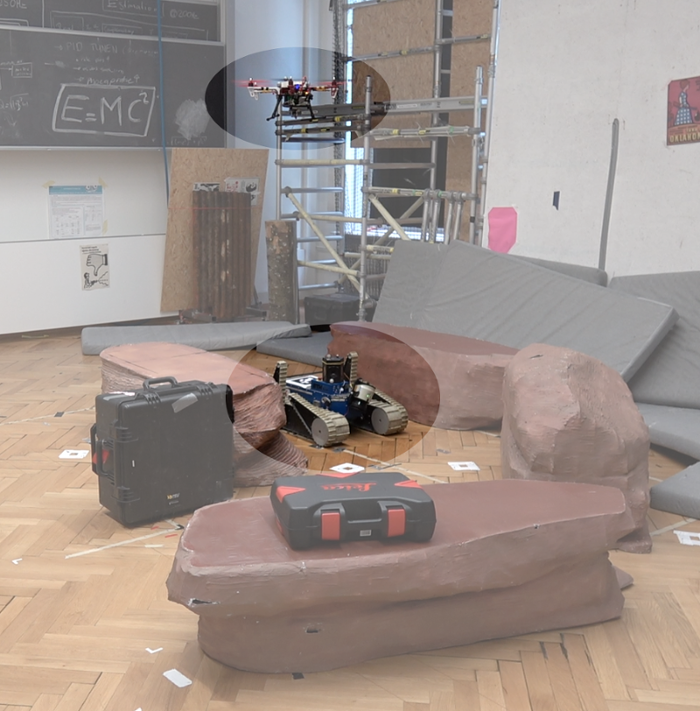
Firstly, we perform structured experiments in a mock-up environment with a ground-truth pose tracking system for all robots, see Fig. 5(b). We evaluate the effectiveness of the visual detection system under varying perceptual conditions, i.e., different payloads on robot, than on detection template, and inside / outside operation using the same detection template. Also, we verify the minimum altitude of the MAV for stable visual servoing.
Then, we map the room with our UGV, request the MAV between different locations, based on the LiDAR-based map, and evaluate the performance. Since, we presently have only one UGV available, we simulate the multi-UGV scenario, by building a first map with the UGV from the starting point, and then placing a visual target at its location. Then, we use the UGV to drive another way from the starting location and build a second map. The locations of the UGVs were chosen to maximize the distance between them in the experiment room, i.e., . Both maps are registered based on their initial alignment. We then let the MAV travel between the visual target that simulates the first UGV and the UGV’s location of the second run. In this experiment, we evaluate the request success, and the drift between the two pose estimations, i.e., VIO for the MAV, and LiDAR-based SLAM for the UGV.
Secondly, we test the full system in both the mock-up scenario, and a realistic disaster scenario within the TRADR project review in Mestre, Italy, see Fig. 5(a). The site consisted of a large decommissioned working hall, featuring various industrial installations, and obstacles on the ground. Here, we demonstrate the full functionality of requesting the MAV, transferring to the UGV and supporting teleoperation with a third-person view by automatic visual servoing.
IV-B Results
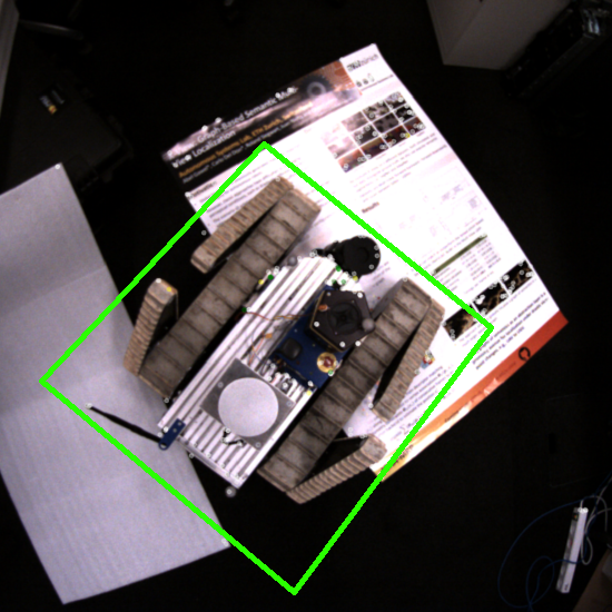
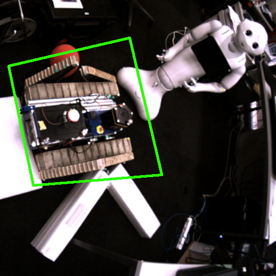
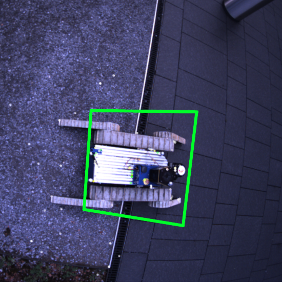
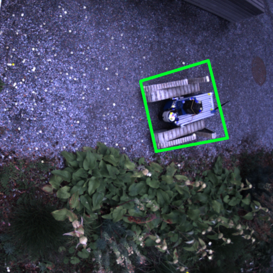
Given the hardware that we used in our experiments, an altitude of above the servoing target showed to be sufficient to follow the UGV in the proposed servoing mode. However, visual detection both using visual features and Apriltags also performed well at greater heights up to the greatest tested height of . While the Apriltag detection is very robust given visibility of the tag, also the visual feature based detection shows to work reliably. Both detection regimes run onboard in real-time. Given that the MAV stays within the height range and maximum radius , both receive at least one correct detection per second without false detections. Samples of the visual feature based detection are illustrated in Fig. 6. However, using feature-based detection, the pose of the robot cannot always be precisely estimated. Variations in the detected bounding box lead to these deviations, as also illustrated in Fig. 6 (bottom row: middle left, and middle right).
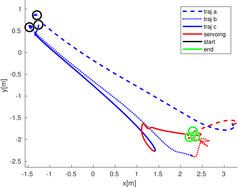
The experiment on repeated transfers between two targets showed satisfying performance. In series of transfers between the targets, the MAV was always able to detect the new target and return to visual servoing above it. We measured a displacement of the UGV locations with respect to the ground truth locations, and an average displacement in -coordinates between the MAV’s position estimate and the ground-truth of , with maximum displacements of up to . Furthermore, we evaluate the acceptable displacement from the target location. In our experimental set-up, the MAV is able to compensate for displacements of , i.e., four times the maximal error, from the target location through visual servoing, as illustrated in Fig. 8. Despite equal goal positions, the flown trajectories differ due to varying initializations of the VIO in the starting location, and drift behaviour during the maneuver execution.
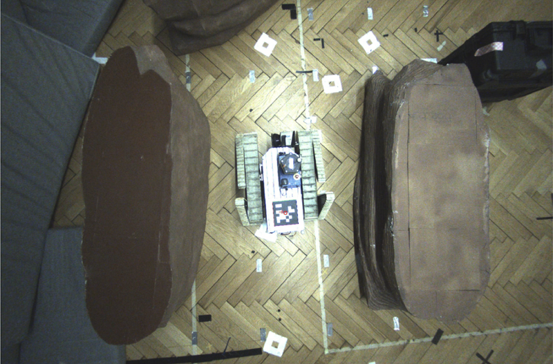
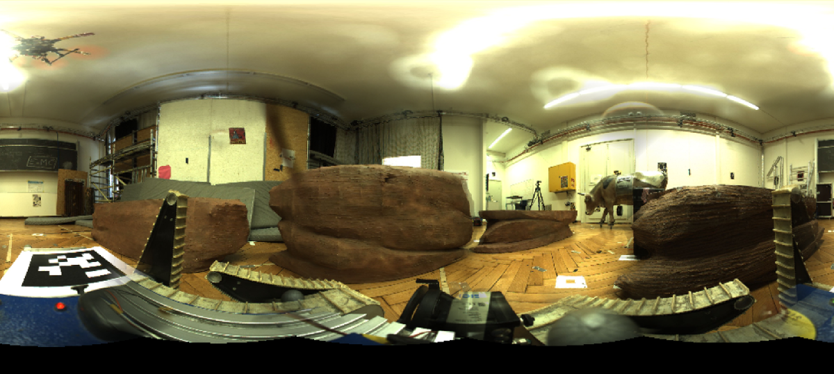
Also, we successfully perform the requesting of the MAV to a UGV, and guiding it through difficult passages by providing a third-person view. Exemplary views from MAV and UGV perspective are illustrated in Fig. 7.
Finally, the system shows to be easily controllable as no trained pilot is required to control the MAV. The system was controlled by several UGV pilots that were not trained in MAV piloting, and successfully completed the experiment parcours with the MAV autonomously following the UGV.
IV-C Discussion
The experimental results show that an interfacing between the localization systems of MAVs with UGVs, and integration with local systems, such as visual servoing can build an efficient real-time collaborative team of robots in GPS-denied environments. Several practical concerns have to be taken into account in designing such systems. Our choice for hovering the MAV in a fixed location within a large margin above the UGV is partly due to using a fixed downward facing camera for both visual servoing and providing the third-person view. Having a constant following of the UGV results in a unsteady image, rendering teleoperation cumbersome. Low tolerances on the location above the UGV can furthermore be difficult to accomplish by the MAV controller. Here, a camera equipped with a gimbal could give a steady image of the target for teleoperation, and enable lower margins in the hovering location, enabling a more steady image stream of the UGV. Furthermore, tight margins cannot be achieved when using visual feature-based detection, causing jumps in the detection.
While the drift in the LiDAR-based localization of the UGVs is negligible in the evaluated scales, the VIO is showing larger drifts. This is partly due to tuning our flight controller for aggressive flying maneuvers, leading to quick transfer times between targets. While our experiments are successful throughout for returning to visual servoing above the new target, less aggressive maneuvers could decrease the drift further. However, our present system can handle up to four times the maximum drift measured in the experiments.
Furthermore, we demonstrated our MAV system for transferring between multiple UGVs, but it is not limited to this. The visual feature based detection enables our system to be allocated further targets within the map during the mission, e.g., locations of interest for periodic inspection. Therefore, the task of the MAV can be extended to periodic inspection using the same building blocks. Another option, however not covered by this work, is the possibility to add active localization sensors such as RFID tags if the visual detection is challenged by occlusions or other perceptually difficult situations.
V Conclusion
In this paper we presented a system for effective collaborative sensing for MAVs and UGVs based on combining global and local localization in GPS-denied SaR environments. We show that we can effectively use an MAV as flying camera to support multiple UGV operators in teleoperation, by providing third-person views. The proposed functionality of global transferring between multiple targets shows to work reliably throughout our experiments. Our integration and evaluation reveals the constraints on each module and compromises to obtain a working reliable system. For instance, the hovering strategy to favor better detection and image quality for the teleoperation task given the use of the same camera for both objectives.
VI Acknowledgement
This work was supported by European Union’s Seventh Framework Program for research, technological development and demonstration under the TRADR project No. FP7-ICT-609763, and by the National Center of Competence in Research (NCCR) Robotics through the Swiss National Science Foundation. The authors would like to thank Rik Bähnemann, Marius Grimm, Alexander Millane, Helen Oleynikova, Dr. Zachary Taylor, and Renaud Dubé for their valuable collaboration and support.
References
- Saakes et al. [2013] D. Saakes, V. Choudhary, D. Sakamoto, M. Inami, and T. Lgarashi, “A teleoperating interface for ground vehicles using autonomous flying cameras,” in Artificial Reality and Telexistence (ICAT), 2013 23rd International Conference on. IEEE, 2013, pp. 13–19.
- Gawel et al. [2017a] A. Gawel, R. Dubé, H. Surmann, J. Nieto, R. Siegwart, and C. Cadena, “3d registration of aerial and ground robots for disaster response: An evaluation of features, descriptors, and transformation estimation,” in Safety, Security, and Rescue Robotics (SSRR), 2017 IEEE International Symposium on, 2017.
- Gawel et al. [2016] A. Gawel, T. Cieslewski, R. Dubé, M. Bosse, R. Siegwart, and J. Nieto, “Structure-based vision-laser matching,” in Intelligent Robots and Systems (IROS), 2016 IEEE/RSJ International Conference on. IEEE, 2016, pp. 182–188.
- Gawel et al. [2017b] A. Gawel, M. Kamel, T. Novkovic, J. Widauer, D. Schindler, B. P. von Altishofen, R. Siegwart, and J. Nieto, “Aerial picking and delivery of magnetic objects with mavs,” in Robotics and Automation (ICRA), 2017 IEEE International Conference on. IEEE, 2017, pp. 5746–5752.
- Cantelli et al. [2013] L. Cantelli, M. Mangiameli, C. D. Melita, and G. Muscato, “Uav/ugv cooperation for surveying operations in humanitarian demining,” in Safety, Security, and Rescue Robotics (SSRR), 2013 IEEE International symposium on. IEEE, 2013.
- Olson [2011] E. Olson, “AprilTag: A robust and flexible visual fiducial system,” in Proceedings of the IEEE International Conference on Robotics and Automation (ICRA). IEEE, May 2011, pp. 3400–3407.
- Rudol et al. [2008] P. Rudol, M. Wzorek, G. Conte, and P. Doherty, “Micro unmanned aerial vehicle visual servoing for cooperative indoor exploration,” in Aerospace Conference, 2008 IEEE. IEEE, 2008.
- Cantelli et al. [2017] L. Cantelli, P. Laudani, C. D. Melita, and G. Muscato, “Uav/ugv cooperation to improve navigation capabilities of a mobile robot in unstructured environments,” in Advances in Cooperative Robotics, 2017, pp. 217–224.
- Saska et al. [2012] M. Saska, T. Krajnik, and L. Pfeucil, “Cooperative uav-ugv autonomous indoor surveillance,” in Systems, Signals and Devices (SSD), 2012 9th International Multi-Conference on. IEEE, 2012.
- Claret et al. [2016] J.-A. Claret, I. Zaplana, and L. Basañez, “Teleoperating a mobile manipulator and a free-flying camera from a single haptic device,” in Safety, Security, and Rescue Robotics (SSRR), 2016 IEEE International Symposium on. IEEE, 2016, pp. 291–296.
- Hui et al. [2013] C. Hui, C. Yousheng, L. Xiaokun, and W. W. Shing, “Autonomous takeoff, tracking and landing of a uav on a moving ugv using onboard monocular vision,” in Control Conference (CCC), 2013 32nd Chinese. IEEE, 2013, pp. 5895–5901.
- Michael et al. [2014] N. Michael, S. Shen, K. Mohta, V. Kumar, K. Nagatani, Y. Okada, S. Kiribayashi, K. Otake, K. Yoshida, K. Ohno et al., “Collaborative mapping of an earthquake damaged building via ground and aerial robots,” in Field and Service Robotics. Springer, 2014, pp. 33–47.
- Bernard et al. [2011] M. Bernard, K. Kondak, I. Maza, and A. Ollero, “Autonomous transportation and deployment with aerial robots for search and rescue missions,” Journal of Field Robotics, vol. 28, no. 6, pp. 914–931, 2011.
- Bähnemann et al. [2017] R. Bähnemann, D. Schindler, M. Kamel, R. Siegwart, and J. Nieto, “A decentralized multi-agent unmanned aerial system to search, pick up, and relocate objects,” Safety, Security, and Rescue Robotics (SSRR), 2017 IEEE International Symposium on, 2017.
- Chaumette [2014] F. Chaumette, “Visual servoing,” in Computer Vision. Springer, 2014, pp. 869–874.
- Lee et al. [2012] D. Lee, T. Ryan, and H. J. Kim, “Autonomous landing of a vtol uav on a moving platform using image-based visual servoing,” in Robotics and Automation (ICRA), 2012 IEEE International Conference on. IEEE, 2012, pp. 971–976.
- Pestana et al. [2014] J. Pestana, J. L. Sanchez-Lopez, S. Saripalli, and P. Campoy, “Computer vision based general object following for gps-denied multirotor unmanned vehicles,” in American Control Conference (ACC), 2014. IEEE, 2014, pp. 1886–1891.
- Bouabdallah et al. [2004] S. Bouabdallah, A. Noth, and R. Siegwart, “Pid vs lqcontrol techniques applied to an indoor micro quadrotor,” in Intelligent Robots and Systems, 2004 IEEE/RSJ International Conference on. IEEE, 2004, pp. 2451–2456.
- Lee et al. [2010] T. Lee, M. Leoky, and N. H. McClamroch, “Geometric tracking control of a quadrotor uav on se(3),” in Decision and Control (CDC), 2010 49th IEEE Conference on. IEEE, 2010, pp. 5420–5425.
- Kamel et al. [2017a] M. Kamel, M. Burri, and R. Siegwart, “Linear vs nonlinear mpc for trajectory tracking applied to rotary wing micro aerial vehicles,” IFAC-PapersOnLine, vol. 50, no. 1, pp. 3463–3469, 2017.
- Burigat et al. [2017] S. Burigat, L. Chittaro, and R. Sioni, “Mobile three-dimensional maps for wayfinding in large and complex buildings: Empirical comparison of first-person versus third-person perspective,” IEEE Transactions on Human-Machine Systems, vol. 47, no. 6, pp. 1029–1039, 2017.
- Minaeian et al. [2016] S. Minaeian, J. Liu, and Y.-J. Son, “Vision-based target detection and localization via a team of cooperative uav and ugvs,” IEEE Transactions on systems, man, and cybernetics: systems, vol. 46, no. 7, pp. 1005–1016, 2016.
- Sukhatme et al. [2001] G. S. Sukhatme, J. F. Montgomery, and R. T. Vaughan, “Experiments with cooperative aerial-ground robots,” Robot Teams: From Diversity to Polymorphism, pp. 345–368, 2001.
- Hsieh et al. [2001] M. A. Hsieh, A. Cowley, J. F. Keller, L. Chaimowicz, B. Grocholsky, V. Kumar, C. J. Taylor, Y. Endo, R. C. Arkin, B. Jung, D. F. Wolf, G. S. Sukhatme, and D. C. MacKenzie, “Adaptive teams of autonomous aerial and ground robots for situational awareness,” Journal of Field Robotics, vol. 24, no. 11–12, pp. 991–1014, 2001.
- Waslander [2013] S. L. Waslander, “Unmanned aerial and ground vehicle teams: Recent work and open problems,” in Autonomous control systems and vehicles. Springer, 2013, pp. 21–36.
- Leutenegger et al. [2011] S. Leutenegger, M. Chli, and R. Y. Siegwart, “Brisk: Binary robust invariant scalable keypoints,” in Computer Vision (ICCV), 2011 IEEE International Conference on. IEEE, 2011, pp. 2548–2555.
- Bloesch et al. [2015] M. Bloesch, S. Omari, M. Hutter, and R. Siegwart, “Robust visual inertial odometry using a direct ekf-based approach,” in Intelligent Robots and Systems (IROS), 2015 IEEE/RSJ International Conference on. IEEE, 2015, pp. 298–304.
- Kamel et al. [2017b] M. Kamel, T. Stastny, K. Alexis, and R. Siegwart, “Model predictive control for trajectory tracking of unmanned aerial vehicles using robot operating system,” in Robot Operating System (ROS). Springer, 2017, pp. 3–39.
- Dubé et al. [2016] R. Dubé, A. Gawel, C. Cadena, R. Siegwart, L. Freda, and M. Gianni, “3d localization, mapping and path planning for search and rescue operations,” in Safety, Security, and Rescue Robotics (SSRR), 2016 IEEE International Symposium on. IEEE, 2016, pp. 272–273.
- MAV
- Micro Aerial Vehicle
- UAV
- Unmanned Aerial Vehicle
- UGV
- Unmanned Ground Vehicle
- TRADR
- “Long-Term Human-Robot Teaming for Robots Assisted Disaster Response”
- SaR
- Search and Rescue
- MPC
- Model Predictive Controller
- VIO
- Visual Inertial Odometry