Azimuthal modulation of electromagnetically induced transparency using structured light
Abstract
Recently a scheme has been proposed for detection of the structured light by measuring the transmission of a vortex beam through a cloud of cold rubidium atoms with energy levels of the -type configuration [N. Radwell et al., Phys. Rev. Lett. 114, 123603 (2015)]. This enables observation of regions of spatially dependent electromagnetically induced transparency (EIT). Here we suggest another scenario for detection of the structured light by measuring the absorption profile of a weak nonvortex probe beam in a highly resonant five-level combined tripod and (CTL) atom-light coupling setup. We demonstrate that due to the closed-loop structure of CTL scheme, the absorption of the probe beam depends on the azimuthal angle and orbital angular momentum (OAM) of the control vortex beams. This feature is missing in simple or tripod schemes, as there is no loop in such atom-light couplings. One can identify different regions of spatially structured transparency through measuring the absorption of probe field under different configurations of structured control light.
pacs:
42.50.−p; 42.50.Gy; 42.50.CtI Introduction
There has been a substantial interest in coherent control of the optical properties of the medium in the last decades Fleischhauer et al. (2005a); Andre et al. (2005); Fleischhauer and Lukin (2000). One remarkable manifestation of a coherently driven medium is the phenomenon of electromagnetically induced transparency (EIT) Harris (1997). EIT is a quantum interference effect where the destructive interference between probability amplitudes of two optical transitions leads to the elimination of absorption and an associated steep variation of the refractive index around the resonant frequency Harris et al. (1990); Boller et al. (1991); Harris (1997). This happens as a result of the dramatic modification of the optical response for a weak probe field when the medium is simultaneously exposed to another, strong laser field. Such a regime of coherent light-matter interaction has led to the discovery of a number of fascinating phenomena: slow and ultraslow light Hau et al. (1999); Budker et al. (1999), light storage and retrieval Phillips et al. (2001); Liu et al. (2001), stationary light Bajcsy et al. (2003) and giant optical nonlinearities Schmidt and Imamoglu (1996); Pack et al. (2006). It was also demonstrated that EIT allows for the coherent manipulation of individual photons and efficient conversion of their quantum states into long-lived atomic coherences Eisaman et al. (2005); Chaneliere et al. (2005). The latter is a desirable feature for all-optical quantum information processing and quantum memory applications Ma et al. (2017); Lukin (2003).
In its simplest form EIT requires only three atomic levels and two light beams in a suitable atomic medium with configuration geometry of the type Andre et al. (2005); Ma et al. (2017); Fleischhauer et al. (2005b). In general, however, EIT is not restricted to this simple scheme, but takes place also in more complex atomic configurations where multiple energy states interact with multiple laser fields McGloin et al. (2001); Paspalakis and Knight (2002a, b); McGloin (2003); Wang et al. (2004); Bhattacharyya et al. (2007); Hamedi et al. (2017); Unanyan et al. (2010); Fleischhauer and Juzeliūnas (2016); Lee et al. (2014). Such complex EIT systems possess a range of useful features, like multiple transparency windows, support of slow light at different frequencies, and the diversity in the optical response characteristics. Typically, the introduction of additional driving fields or atomic levels allows better flexibility and control over the EIT. For example, by applying a microwave field to the lower levels of the scheme, enhancement or suppression of EIT can be observed Li et al. (2009). On the other hand, by adding an extra optical field to the scheme the group velocity of a probe pulse can be effectively manipulated Agarwal et al. (2001). Despite numerous studies on EIT, there is still a considerable interest in developing more advanced atom-light coupling schemes and investigation of the associated new properties.
An increased attention has turned recently to the usage of the special optical beams in EIT, particularly optical vortices Akin et al. (2015). An optical vortex is a beam with nonzero orbital angular momentum (OAM), meaning that its optical phase is a function of azimuthal coordinate and the wavefront is helical Allen et al. (1992); Yao and Padgett (2011). Some important features of OAM in the EIT regime have been demonstrated including resonance narrowing Chanu and Natarajan (2013) or the robustness of stored OAM state to decoherence Pugatch et al. (2007), suggesting vortex usability in the EIT-related applications. Moreover, OAM serves as an additional degree of freedom for a photon and hence represents a system of a higher dimension for the high capacity information transmission. Quite recently, the OAM-based long distance communication over multi-kilometer ranges have been demonstrated Krenn et al. (2016), and quantum entanglement of photons carrying high order topological charges have been reported Fickler et al. (2016). Combining the increased information capacity of the vortex beams with the EIT-based possibilities of coherent photon manipulation and trapping, this concept becomes a promising approach for the quantum information science Veissier et al. (2013).
One may take advantage of such a combined OAM and EIT approach to study the characteristics of OAM in the atomic ensembles Ruseckas et al. (2011, 2013). To this end, a couple of recent studies have demonstrated how the coherent properties of EIT make it possible to identify the OAM information by producing spatially variable absorption patterns Han et al. (2012); Radwell et al. (2015). It was suggested to identify the OAM by converting its spatial phase information to the corresponding intensity distribution using a microwave field between the ground levels in the scheme Han et al. (2012). In a remarkable work by Radwell et al. Radwell et al. (2015), the formation of the spatially varying EIT was demonstrated using light beam with both azimuthally varying polarization and a phase structure. In this work the existence of a spatially varying dark state was shown at specific angles with the symmetry determined by the input light polarization. However, the proposal dealt with a simple three-level atom-light coupling scheme of the -type which has obvious limitations. Moreover, this study concentrated on situation where the incident probe beam carries the OAM.
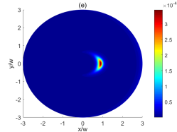
Here we suggest another scenario for the detection of structured light patterns and formation of spatially varying optical transparency based on a more complex combined tripod and (CTL) atom-light coupling scheme (see Fig. 1(a)). Note that the spatially varying optical transparency reported in Radwell et al. (2015) is achieved by exposing a three-level -type atomic scheme to a single light beam with an azimuthally varying polarization and phase structure. The left and right-handed circular polarization components form the probe and control fields for the EIT transition via a Hanle resonance Renzoni et al. (1997), resulting in an azimuthal variation of the dynamics of the atomic ensemble. On the other hand, here we consider a situation in which the incident probe beam does not have an optical vortex, whereas the control fields carry optical vortices. We demonstrate that due to the closed-loop structure of the CTL scheme, the probe absorption depends on the azimuthal angle and the OAM of the control vortex beams. This feature is missing in simple or tripod schemes as there is no loop in such atom-light couplings. In that case, even if the control fields carry optical vortices ( and being the azimuthal angle and OAM number, respectively), the probe field does not feel the effect induced by vortex control beams as the magnitude squared of control fields appears in expression for the probe susceptibility Paspalakis and Knight (2002a, b). We show that a more complex atomic setup made by a combination of two and tripod schemes can be utilized to overcome this downside enabling to measure the regions of optical transparency. Such a model may provide a promising approach to identify the OAM of control fields by mapping the spatially dependent absorption profile of the probe field.
II Model and formulation
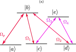
We consider a five-level CTL atom-light coupling scheme shown in Fig. 1(a). The scheme is made of a four-level tripod subsystem (consisting of atomic levels , , , and ) as well as a three-level subsystem (including atomic levels , , and ) coherently coupled to each other by a probe field and four control laser fields. The probe and control fields are assumed to co-propagate along the same direction. Four control laser fields represented by Rabi frequencies , and couple two excited states and via two different pathways and making a four-level closed-loop coherent coupling scheme described by the Hamiltonian ()
| (1) |
A weak probe field described by a Rabi frequency couples then the closed-loop subsystem to a ground level via the atomic transition . The destructive interference between different transition pathways induced by the control and probe beams can make the medium transparent for the resonant probe beam in a narrow frequency range due to the EIT Hamedi et al. (2017). The total Hamiltonian of the system involving all five atomic levels of the CTL level scheme is described by
| (2) |
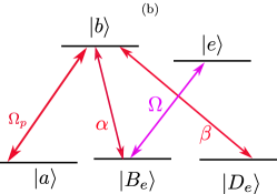
In a new basis, the Hamiltonian for the atomic four-level subsystem (1) can be expressed as Hamedi et al. (2017)
| (3) |
where
| (4) | ||||
| (5) |
are the internal dark and bright states for the -scheme made of the two ground states states and , as well as an excited states . In writing Eq. (3), we define
| (6) | ||||
| (7) |
and the total Rabi frequency
| (8) |
By changing the coefficients and one arrives at three different situations: i) both and are nonzero; ii) is zero; iii) is zero Hamedi et al. (2017). When both and are nonzero (), there exists a superposition state
| (9) |
which has no contribution from both bare excited states and . Assuming that the probe field is much weaker than the control fields, it follows from Eq. (9) that the superpositon state is approximately equal to , indicating that the ground state becomes a dark state and not interact with the light forming a transparency window around the zero probe detuning .
III Vortex dependent probe absorption
In the CTL scheme, the dynamics of the probe field and the atomic coherences can be described by the optical Bloch equations. The reduced optical Bloch equations in the new basis are
| (10) | ||||
| (11) | ||||
| (12) | ||||
| (13) |
where is the optical coherence corresponding to the probe transition of , while , or are the ground-state coherence between and , or . Note that we have assumed that the probe field is much weaker than the control ones. In that case most atomic population is in the ground state, and one can treat the probe field as a perturbation. All fast-oscillating exponential factors associated with central frequencies and wave vectors have been eliminated from the equations, and only the slowly-varying amplitudes are retained. Here we have defined the probe detuning as where is a central frequency of the probe field. The control fields are assumed to be on resonance. Two excited states and decay with rates and , respectively.
As it is known, the imaginary part of corresponds to the probe absorption. From the reduced OB equations (10)–(13) it is easy to obtain the steady-state solution to the density matrix element
| (14) |
where .
Having obtained the coherence term , the analytical solution for the probe absorption can be easily obtained, after some straightforward algebra
| (15) |
with
| (16) |
and
| (17) |
One can see that the probe absorption for the CTL system has now a term
| (18) |
entering to the parameter featured in Eq. (16), where
| (19) |
represents the quantum interference between the four control fields.
This indicates that if a single control field or a combination of several control fields carry an optical vortex () in the CTL scheme, the linear absorption of the probe field given by Eq (15) depends on the OAM of the control field(s) through the parameter . Note that this does not mean that the probe beam can acquire the OAM of control field(s) when propagating in such a medium. The incoming probe beam does not have any vortex initially at the beginning of the atomic medium. However, due to the closed-loop structure of the atomic system, the probe beam subsequently develops some OAM features by propagating in such a highly resonant medium, making the transverse profile of the probe beam spatially varying. This does not necessary mean that one arrives at a pure vortex beam. Although the probe field acquires some non-zero OAM components along with the zero OAM component, the intensity of the probe beam does not go to zero at some transverse point.
The origin of such sensitivity of the probe field to the OAM of the control fields originates from the fact that the CTL system is phase-dependent Hamedi et al. (2017). Such a phase sensitivity is contained in the parameter featured in Eq. (19). Therefore, the linear susceptibility and hence the probe absorption will depend on the azimuthal angle of the control fields carrying the OAM. This can be exploited to measure the regions of spatially varying transparency through measuring the linear absorption of probe field. In addition, it may provide a promising approach to identify the winding number of control fields by mapping the spatially dependent absorption profile of the probe field.
IV Azimuthal modulation of absorption profile
In last Section we demonstrated that the application of structured lights make the probe absorption profile given by Eq. (15) spatially dependent due to the quantum interference term . This indicates that by measuring the absorption profile of probe field we can determine the regions of optical transparency or absorption. Apparently, different cases of interaction of the atom with the vortex control beams result in different absorption profiles so that different patterns can be achieved for regions of spatially structured transparency. In what follows we investigate the spatially dependent EIT for the CTL system near the resonance (i. e., ) by considering different cases of structured control light. We assume and all parameters are scaled with which should be of the order of MHz, like, for example, in cesium (Cs) atoms. We will consider the following configurations with increasing number of vortex beams: a) only the control field carries an optical vortex, the other control fields and have no vortices; b) two control fields and are vortex beams; c) the control fields and carry optical vortices; d) two control fields and are vortex beams; e) three control fields , and are vortex beams; f) all four control fields carry optical vortices. The amplitude of a vortex beam is
| (20) |
where is an integer representing the vorticity, corresponds to the distance from the vortex core (cylindrical radius) and stands for the beam waist parameter.
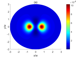
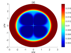
IV.0.1 Situation (a): single vortex beam
At first let us consider a situation where the control field carries an optical vortex , yet other control fields and have no vortices (Fig. 2(a)). Thus the Rabi-frequency of vortex beam is
| (21) |
where is the azimuthal angle, is an integer representing the vorticity of control field, while is defined by Eq. 20 with . The other nonvortex control field Rabi-frequencies are defined by
| (22) | ||||
| (23) | ||||
| (24) |
Under this situation, the quantum interference term defined by Eq. (19) takes the form
| (25) |
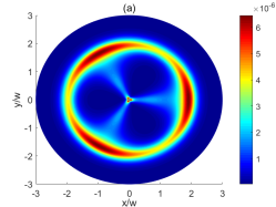
Figure 3 illustrates the absorption profile based on Eq. (15) for different vorticities . The bright structures represent the positions of low light transmission, while the blue areas correspond to the regions of optical transparency. As it can be seen, for an absorption maxima is immersed in regions of optical transparency (Fig. 3(a)). For larger numbers, the absorption profile displays a -fold symmetry distributed in regions of spatial EIT (Figs. 3(b)–(e)). Therefore, one can easily distinguish an unknown vorticity of a vortex control beam just by counting the bright structures appearing in the absorption profile of the probe field.
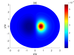
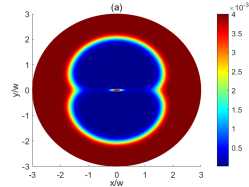
At the core of vortex beam when the intensity of control field is zero, the CTL scheme reduces to an M-type atom-light coupling configuration for which no loss is expected Li et al. (2005); Hong et al. (2012). Away from the vortex core when , the medium is transparent as long as Hamedi et al. (2017) (see also Eqs. (14) and (18)). However, for some specific spatial regions and depending on different vorticities the parameter in Eq. (18) may become zero. In this case Eq. (14) reduces to
| (26) |
This is the case when the five-level CTL scheme converts to the conventional -type atomic structure for which strong absorption is expected Hamedi et al. (2017). This is the origin of absorption maximums appearing in absorption profiles illustrated in Figs. 3(a)–(e). The -fold symmetry of absorption profile observed in Fig. 3 satisfies the predicted cosinusoidal variation of quantum interference term with a periodicity of given in Eq. (25).
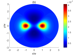
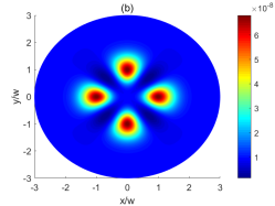
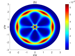
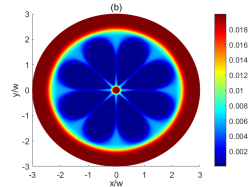
IV.0.2 Situation (b): two vortex beams and
We consider two control fields and as vortex beams (Fig. 2(b)):
| (27) | ||||
| (28) |
where and are defined by Eq. 20 with . Rabi frequencies of other two nonvortex beams do not depend on the azimuthal angle :
| (29) | ||||
| (30) |
In this case, the quantum interference term of Eq. (19) takes the form
| (31) |
In Fig. 4 we show the absorption profile when and are structured light. Let us first consider that the vortices are equal: . In this case, Eq. (31) reduces to
| (32) |
and the spatial profile of probe absorption displays a -fold symmetry (Figs. 4 (a)–(d)) satisfying the cosinusoidal behavior of quantum interference term featured in Eq. (32). The medium is transparent at the core of vortex beams as the five-level CTL scheme is now equivalent to a three-level -type system which is decoupled from the two level system involving the states and Hamedi et al. (2017).
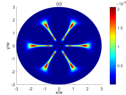
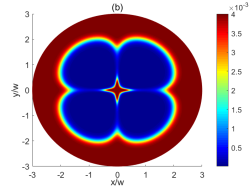
When the vortices are different , the number of absorption peaks becomes , and the symmetry of absorption profile obeys from the predicted cosinusoidal behavior of the parameter with a periodicity of , given in Eq. (31). For instance, for the case of different vortices and the number of symmetrical absorption peaks becomes seven as illustrated in Fig. 4(e).
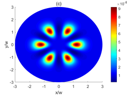
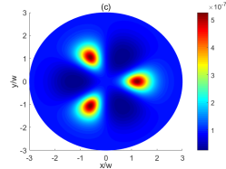
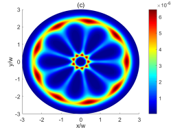
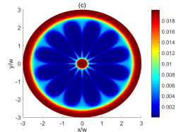
IV.0.3 Situation (c): two vortex beams and
In the situation, shown in Fig. 2(c), the control fields with Rabi frequencies and are assumed to carry optical vortices
| (33) | ||||
| (34) |
where and are defined by Eq. 20 with , yet other control beams are nonvortex beams,
| (35) | ||||
| (36) |
Equation. (19) then becomes
| (37) |
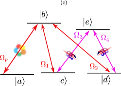
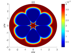
When , the system simplifies to a tripod atom-light coupling structure, hence, we expect optical transparency at the core of vortices Paspalakis and Knight (2002b) (see Fig. 5). For the opposite helicity optical vortices , the quantum interference term is the same as Eq. (32), yielding a -fold symmetry of structured transparency profile, as illustrated in Figs. 5 (a)–(d). When , Eq. (37) necessitates a symmetry of the absorption profile (Fig. 5 (e)).
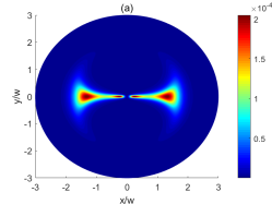
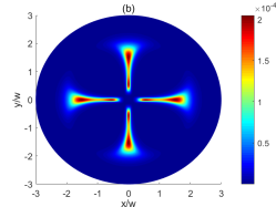
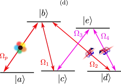
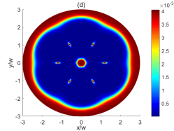
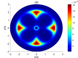
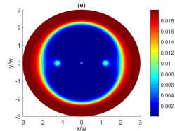
IV.0.4 Situation (d): two vortex beams and
Now we assume that the two control fields and are structured light (Fig. 2(e)),
| (38) | ||||
| (39) |
where and are defined by Eq. 20 with , and
| (40) | ||||
| (41) |
The quantum interference of Eq. (19) becomes
| (42) |
For the opposite helicity vortex beams , the quantum interference term changes to Eq. (32) and the absorption profile demonstrates again a - fold symmetry (Figs. 6(a)–(c)).
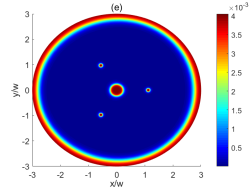
When the vortices are not the same , the symmetry of spatial absorption profile follows from Eq. 42, for example for and (Fig. 6(d)) and and (Fig. 6(e)), -fold and -fold symmetries are observed. Note that the core of absorption image now corresponds to regions of low light transmission as for this situation the medium becomes an absorptive -type medium Sheng et al. (2011); Yang et al. (2015) at the core of control vortex beams.
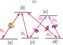
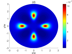
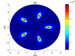
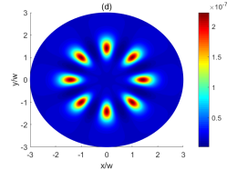
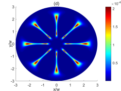
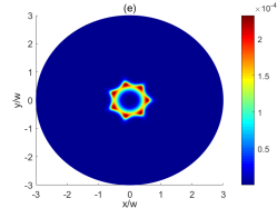
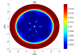
IV.0.5 Situation (e): three vortex beams , and
We consider three control fields , and as vortex beams (Fig. 2(d)),
| (43) | ||||
| (44) | ||||
| (45) |
with , and defined by Eq. 20 and . The nonvortex beam has the Rabi frequency
| (46) |
In this case, the quantum interference term of Eq. (19) reads
| (47) |
When two control beams and have the same vortices while they are of opposite helicity with the vortex beam (), the quantum interference term becomes
| (48) |
Obviously, the cosinusoidal behavior of given in Eq. (48) leads to a -fold symmetry of spatial distribution of absorption profile, as depicted in Figs. 7(a)–(c). The symmetry of patterns changes to -fold for (Figs. 7(d)–(e)). Note that the medium is now equivalent to a three-level scheme at the core of control vortex beams,resulting in an optical transparency for .
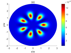
IV.0.6 Situation (f): all control fields are vortex beams
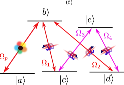
Finally, let us consider a situation when all control fields are assumed to be vortex beams (Fig. 2(f))
| (49) | ||||
| (50) | ||||
| (51) | ||||
| (52) |
with, , and defined by Eq. 20 where . For this situation the system reduces to a two-level absorptive medium at the core of optical vortices, therefore we expect to observe low light transmission in the absorption image of probe field when . The quantum interference term Eq. (19) changes to
| (53) |
When , Eq. 53 simplifies
| (54) |
and absorption profile shows a -fold symmetry, as illustrated in Figs. 8(a)–(c). For different optical vortices, Eq. 53 results in a -symmetry of absorption profile. For example, for , ,, we observe a -fold symmetry (Fig. 8(d)), while for , ,, the absorption profile exhibits a fold symmetry (Fig. 8(e)).
V Concluding Remarks
In conclusion, we have theoretically investigated the spatially structured optical transparency in a five-level CTL atom-light coupling scheme illuminated by a weak nonvortex probe beam as well as control laser fields of larger intensity which can carry OAMs. As a result of the closed-loop structure of CTL scheme, the linear susceptibility of the weak probe beam depends on the azimuthal angle and OAM of the control beams. Therefore, it is possible to obtain information about positions of low light transmission or optical transparency through measuring the resulting absorption spectra. Different situations where one or a combination of control fields are vortex beams are considered, and different symmetry situations for the absorption profile are obtained. It is shown that the the quantum interference parameter featured in Eq. (19) governs the symmetry of absorption profiles. In particular, the absorption image of probe field shows -, - -, and even -fold symmetries due to -, - - or -fold cosinusoidal behavior of the parameter , defined by Eq. (19). The spatially varying optical transparency may find potential applications in storage of high-dimensional optical information in phase dependent quantum memories.
A possible realistic experimental realization of the proposed combined tripod and setup can be implemented e.g. for the Cs atoms. The lower levels , and can be assigned to , and , respectively. Two excited states and can be attributed to and , respectively.
Acknowledgements.
This research was funded by the European Social Fund under grant No. 09.3.3-LMT-K-712-01-0051.References
- Fleischhauer et al. (2005a) M. Fleischhauer, A. Imamoglu, and J. P. Marangos, Rev. Mod. Phys. 77, 633 (2005a).
- Andre et al. (2005) A. Andre, M. D. Eisaman, R. L. Walsworth, A. S. Zibrov, and M. D. Lukin, J. Phys. B: At. Mol. Opt. Phys. 38, S589 (2005).
- Fleischhauer and Lukin (2000) M. Fleischhauer and M. D. Lukin, Phys. Rev. Lett. 84, 5094 (2000).
- Harris (1997) S. E. Harris, Phys. Today 50, 36 (1997).
- Harris et al. (1990) S. E. Harris, J. E. Field, and A. Imamoglu, Phys. Rev. Lett. 64, 1107 (1990).
- Boller et al. (1991) K.-J. Boller, A. Imamoglu, and S. E. Harris, Phys. Rev. Lett. 66, 2593 (1991).
- Hau et al. (1999) L. V. Hau, S. E. Harris, Z. Dutton, and C. H. Behroozi, Nature 397, 594 (1999).
- Budker et al. (1999) D. Budker, D. F. Kimball, S. M. Rochester, and V. V. Yashchuk, Phys. Rev. Lett. 83, 1767 (1999).
- Phillips et al. (2001) D. F. Phillips, A. Fleischhauer, A. Mair, R. L. Walsworth, and M. D. Lukin, Phys. Rev. Lett. 86, 783 (2001).
- Liu et al. (2001) C. Liu, Z. Dutton, C. H. Behroozi, and L. V. Hau, Nature 409, 490 (2001).
- Bajcsy et al. (2003) M. Bajcsy, A. S. Zibrov, and M. D. Lukin, Nature 426, 638 (2003).
- Schmidt and Imamoglu (1996) H. Schmidt and A. Imamoglu, Optics Letters 21, 1936 (1996).
- Pack et al. (2006) M. V. Pack, R. M. Camacho, and J. C. Howell, Phys. Rev. A 74, 013812 (2006).
- Eisaman et al. (2005) M. D. Eisaman, A. Andre, F. Massou, M. Fleischhauer, A. S. Zibrov, and M. D. Lukin, Nature 438, 837 (2005).
- Chaneliere et al. (2005) T. Chaneliere, D. N. Matsukevich, S. D. Jenkins, S.-Y. Lan, T. A. B. Kennedy, and A. Kuzmich, Nature 438, 833 (2005).
- Ma et al. (2017) L. Ma, O. Slattery, and X. Tang, J. Opt. 19, 043001 (2017).
- Lukin (2003) M. D. Lukin, Rev. Mod. Phys. 75, 457 (2003).
- Fleischhauer et al. (2005b) M. Fleischhauer, A. Imamoglu, and J. P. Marangos, Rev. Mod. Phys. 77, 633 (2005b).
- McGloin et al. (2001) D. McGloin, D. J. Fulton, and M. H. Dunn, Optics Commun. 190, 221 (2001).
- Paspalakis and Knight (2002a) E. Paspalakis and P. L. Knight, Phys. Rev. A 66, 015802 (2002a).
- Paspalakis and Knight (2002b) E. Paspalakis and P. L. Knight, J. Opt. B: Quantum Semiclass. Opt. 4, S372 (2002b).
- McGloin (2003) D. McGloin, J. Phys. B: At. Mol. Opt. Phys. 36, 2861 (2003).
- Wang et al. (2004) J. Wang, L. B. Kong, X. H. Tu, K. J. Jiang, K. Li, H. W. Xiong, Y. Zhu, and M. S. Zhan, Phys. Lett. A 328, 437 (2004).
- Bhattacharyya et al. (2007) D. Bhattacharyya, B. Ray, and P. N. Ghosh, J. Phys. B: At. Mol. Opt. Phys. 40, 4061 (2007).
- Hamedi et al. (2017) H. R. Hamedi, J. Ruseckas, and G. Juzeliūnas, J. Phys. B: At. Mol. Opt. Phys. 50, 185401 (2017).
- Unanyan et al. (2010) R. G. Unanyan, J. Otterbach, M. Fleischhauer, J. Ruseckas, V. Kudriašov, and G. Juzeliūnas, Phys. Rev. Lett. 105, 173603 (2010).
- Fleischhauer and Juzeliūnas (2016) M. Fleischhauer and G. Juzeliūnas, “Slow, stored and stationary light,” in Optics in Our Time, edited by M. D. Al-Amri, M. El-Gomati, and M. S. Zubairy (Springer International Publishing, Cham, 2016) pp. 359–383.
- Lee et al. (2014) M.-J. Lee, J. Ruseckas, C.-Y. Lee, V. Kudriasov, K.-F. Chang, H.-W. Cho, G. Juzeliūnas, and I. A. Yu, Nat. Commun. 5, 5542 (2014).
- Li et al. (2009) H. Li, V. A. Sautenkov, Y. V. Rostovtsev, G. R. Welch, P. R. Hemmer, and M. O. Scully, Phys. Rev. A 80, 023820 (2009).
- Agarwal et al. (2001) G. S. Agarwal, T. N. Dey, and S. Menon, Phys. Rev. A 64, 053809 (2001).
- Akin et al. (2015) T. G. Akin, S. P. Krzyzewski, A. M. Marino, and E. R. I. Abraham, Optics Commun. 339, 209 (2015).
- Allen et al. (1992) L. Allen, M. W. Beijersbergen, R. J. C. Spreeuw, and J. P. Woerdman, Phys. Rev. A 45, 8185 (1992).
- Yao and Padgett (2011) A. M. Yao and M. J. Padgett, Advances in Optics and Photonics 3, 161 (2011).
- Chanu and Natarajan (2013) S. R. Chanu and V. Natarajan, Optics Commun. 295, 150 (2013).
- Pugatch et al. (2007) R. Pugatch, M. Shuker, O. Firstenberg, A. Ron, and N. Davidson, Phys. Rev. Lett. 98, 203601 (2007).
- Krenn et al. (2016) M. Krenn, J. Handsteiner, M. Fink, R. Fickler, R. Ursin, M. Malik, and A. Zeilinger, Proc. Natl Acad. Sci. 113, 13648 (2016).
- Fickler et al. (2016) R. Fickler, G. Campbell, B. Buchler, P. K. Lam, and A. Zeilinger, Proc. Natl Acad. Sci. 113, 13642 (2016).
- Veissier et al. (2013) L. Veissier, A. Nicolas, L. Giner, D. Maxein, A. S. Sheremet, E. Giacobino, and J. Laurat, Optics Letters 38, 712 (2013).
- Ruseckas et al. (2011) J. Ruseckas, A. Mekys, and G. Juzeliūnas, Phys. Rev. A 83, 023812 (2011).
- Ruseckas et al. (2013) J. Ruseckas, V. Kudriašov, I. A. Yu, and G. Juzeliūnas, Phys. Rev. A 87, 053840 (2013).
- Han et al. (2012) L. Han, M. Cao, R. Liu, H. Liu, W. Guo, D. Wei, S. Gao, P. Zhang, H. Gao, and F. Li, Europhys. Lett. 99, 34003 (2012).
- Radwell et al. (2015) N. Radwell, T. W. Clark, B. Piccirillo, S. M. Barnett, and S. Franke-Arnold, Phys. Rev. Lett. 114, 123603 (2015).
- Renzoni et al. (1997) F. Renzoni, W. Maichen, L. Windholz, and E. Arimondo, Phys. Rev. A 55, 3710 (1997).
- Li et al. (2005) L. Li, H. Guo, F. Xiao, X. Peng, and X. Chen, Journal of the Optical Society of America B 22, 1309 (2005).
- Hong et al. (2012) Y. Hong, Y. Dong, Z. Mei, F. Bo, Z. Yan, and W. Jin-Hui, Chinese Phys. B 21, 114207 (2012).
- Sheng et al. (2011) J. Sheng, X. Yang, U. Khadka, , and M. Xiao, Optics Express 19, 17059 (2011).
- Yang et al. (2015) X. Yang, K. Ying, Y. Niu, and S. Gong, J. Opt. 17, 045505 (2015).