Wideband Time-Domain Digital Backpropagation via
Subband
Processing and Deep Learning
1 Introduction
Real-time digital backpropagation (DBP) based on the split-step Fourier method (SSFM) is widely considered to be impractical due to the complexity of the chromatic dispersion (CD) steps. To address this problem, finite impulse response (FIR) filters may be used instead of fast Fourier transforms (FFTs) to perform time-domain CD filtering3, 4, 5, 6, 7, 8, 9. Indeed, the FIR filters can be as short as taps per SSFM step, provided that the step size is sufficiently small (i.e., many steps are used) and the filters in all steps are jointly optimized8.
The complexity of time-domain DBP (TD-DBP) is dominated by the total number of CD filter taps in all steps. Recent work has focused on relatively narrowband signals (e.g., Gbaud in8 and Gbaud in7, 5, 6) for which the overall CD memory is low. Since the memory increases quadratically with bandwidth, it is not clear if TD-DBP can be scaled gracefully also to more wideband signals.
In this paper, we consider a -Gbaud signal where the delay spread per km amounts to symbol periods. It is shown that TD-DBP can still offer a good performance–complexity trade-off by leveraging digital subband processing. In particular, the group delay difference in different subbands can be compensated almost entirely using delay elements. A fractional delay filter is only needed after the last SSFM step.
2 Subband Processing and Related Work
Subband processing has been previously studied for both linear10, 11, 12, 13 and nonlinear14, 15, 16 impairment compensation. The idea is to split the received signal into parallel signals using a filter bank. Assuming a bandwidth reduction by , the delay spread per subband signal is reduced by . This can allow for significant complexity savings.
We consider a uniformly modulated filter bank as shown in Fig. 1. The subband signals are obtained by filtering a downconverted version of with a prototype filter , where is the frequency shift. The signals are then downsampled by and jointly processed. Finally, a synthesis filter bank reassembles the signal . Certain subbands may be inactive if they do not contain useful signal components. Active subbands are indexed symmetrically around the central subband according to .
Example 1: Consider a -Gbaud signal sampled at GHz. For subbands, most of the spectrum falls within the central subbands, see Fig. 1. Thus, one may set .


3 Proposed DSP Architecture
A theoretical foundation for DBP based on subband processing can be obtained by inserting the split-signal assumption into the NLSE. This leads to a set of coupled equations which can then be solved numerically. Our approach is based on the SSFM proposed in17. The method is essentially equivalent to the standard SSFM for each subband, except that all sampled intensity signals are jointly processed with a multiple-input multiple-output (MIMO) filter prior to the nonlinear phase rotation step. This accounts for cross-phase modulation (XPM) between subbands but not four-wave mixing (FWM) because no phase information is exchanged. The method can also be used for DBP of noncoherent subband signals, e.g., in wavelength division multiplexing scenarios with different local oscillators. This was done in 14.
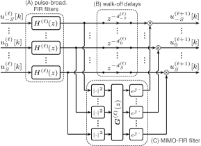
Fig. 2 shows the proposed architecture, which consists of the following three main components:
-
(A)
Short filters compensate for pulse broadening in each subband and step .
-
(B)
Delay elements are used to compensate the group delay difference in different subbands.
-
(C)
The MIMO filtering is performed in the time domain using sparse tensor decompositions.
Compared to17, 14, no FFT/IFFT pairs are used. In the following, the individual components (A)–(C) in Fig. 2 are described in more detail.
4 (A) Pulse-Broadening FIR Filters
The frequency response of an ideal CD compensation filter is where and is the propagation distance. Since the subband signals are downconverted relative to the carrier frequency, the filter responses have to be shifted as well. The ideal response for subband is
where with compensates the walk-off relative to the central subband, and . The filters correspond to and compensate for pulse broadening which is independent of . Thus, the same filter can be used in all subbands. Moreover, the filters are symmetric since is symmetric, allowing for a folded DSP implementation with real multiplications (RMs) assuming complex filter taps. Different filters are used in different steps (even if the step size is the same) to avoid accumulating truncation errors that arise from approximating with finite-length filters8.
5 (B) Walk-off Delays and SSFM Step Size
The group delay depends linearly on the propagation distance . The step size can thus be chosen such that for all is an integer multiple of the subband sampling interval :
| (1) |
where is the group delay difference in two neighboring subbands. Thus, as long as the step size is an integer multiple of , the walk-off can be compensated exactly using delay elements.
Example 2: For the parameters in Ex. 1, , and ps2/km, we have km.
It is clear that the transmission distance is not necessarily an integer multiple of . Therefore, a fractional delay filter is inserted after the last step to account for any remaining non-integer delay prior to the synthesis filter bank.
6 (C) MIMO-FIR Filter
Let be the -transform of the intensity signal after the filter in subband and step and define . The nonlinear phase shift is computed based on filtered intensity signals whose -transform is
| (2) |
where is an polynomial matrix. The order of the (real and nonsymmetric) MIMO filter, i.e., the largest polynomial degree in , is assumed to be equal to the maximum number of walk-off delay elements in step .
Example 3: For the parameters as before and a step size , the group delay difference of the outermost subbands corresponds to . Thus, the order of is .
7 Joint Filter Optimization via Deep Learning
“Unrolling” all SSFM steps in Fig. 2 leads to a multi-layer computation graph similar to a deep neural network7, 8. Thus, joint optimization of all filters can be achieved using tools from machine learning, in particular deep learning via stochastic gradient descent. The tunable parameters are
-
•
the prototype filters and ,
-
•
the filters for ,
-
•
the MIMO filters for ,
-
•
the fractional delay filters for .
The optimization is performed in TensorFlow using the Adam optimizer. The mean squared error between the transmitted and received data symbols is used as a loss function, assuming a matched filter and phase offset rotation after the subband processing. Initially, the prototype filters are raised-cosine filters, the filters are pre-optimized using least-squares methods8, and the filters are 8-tap Lagrange interpolation filters. The MIMO filters are randomly initialized.
A potential issue in terms of complexity is the large number of MIMO filter coefficients, e.g., the filter in Ex. 3 is a tensor with real coefficients. We assume that these tensors can be decomposed into a cascade of sparse tensors , where all have dimension and order . To encourage sparsity during training, we employ -norm regularization for all MIMO filters.
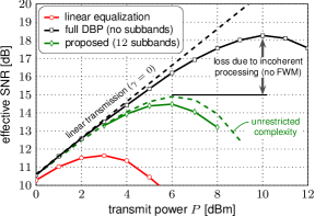
8 Results and Discussion
We consider a -Gbaud signal (root-raised cosine, roll-off, Gaussian symbols), km of fiber (dB/km, ps2/km, 1/W/km), and amplifiers with dB noise figure. Forward propagation is simulated using the standard SSFM with samples/symbols and logarithmic steps per span (StPS). Subband TD-DBP is performed with , , , and a uniform step size of km for the first steps (see Ex. 2). The last step size is km for a total of steps ( StPS on average).
The results after training are shown in Fig. 3. Our method achieves a dB SNR improvement over linear equalization. The loss with respect to full DBP ( samples/symbol, StPS) is mostly due to the incoherent subband processing. To illustrate this, we also show results assuming essentially unrestricted complexity (dashed line), where , , and frequency-domain filtering according to17 with StPS is used.
To quantify the complexity, we use RMs focusing on the pulse-broadening and MIMO filters which dominate the requirements. The results were obtained with -tap pulse-broadening filters () which can be implemented using RMs. For the MIMO filters, is used. The learned coefficients were thresholded, after which only out of total coefficients were nonzero. This gives RMs per subband and step on average, i.e., RMs in total. A similar analysis for frequency-domain overlap-and-add filtering is presented in 14. Following the same arguments, the number of RMs for our scenario is per subband and step with an optimized FFT size of . This is significantly more than required using TD-DBP.
9 Conclusions
We have proposed a novel DSP architecture for DBP based on subband processing. Our method uses short FIR filters for the CD compensation to achieve computational efficiency. It was shown that a proper step size choice can significantly simplify the walk-off compensation by using delay elements. Lastly, the complexity of the XPM MIMO filters proposed in17 can be reduced by applying sparse tensor decomposition.
10 Acknowledgements
This work is part of a project that has received funding from the European Union’s Horizon 2020 research and innovation programme under the Marie Skłodowska-Curie grant agreement No. 749798. The work was also supported in part by the National Science Foundation (NSF) under Grant No. 1609327. Any opinions, findings, recommendations, and conclusions expressed in this material are those of the authors and do not necessarily reflect the views of these sponsors.
References
- 1
- 2
- 3 L. Zhu et al., “Complementary FIR filter pair for distributed impairment compensation of WDM fiber transmission,” IEEE Photon. Technol. Lett. 21, 292–294 (2009).
- 4 G. Goldfarb and G. Li, “Efficient backward-propagation using wavelet-based filtering for fiber backward-propagation,” Opt. Express 17, 814–816 (2009).
- 5 C. Fougstedt et al., “Time-domain digital back propagation: Algorithm and finite-precision implementation aspects,” in Proc. OFC, (Los Angeles, CA, 2017).
- 6 C. Fougstedt et al., “Finite-precision optimization of time-domain digital back propagation by inter-symbol interference minimization,” in Proc. ECOC, (Gothenburg, Sweden, 2017).
- 7 C. Häger and H. D. Pfister, “Nonlinear interference mitigation via deep neural networks,” in Proc. OFC, (San Diego, CA, 2018).
- 8 ——, “Deep learning of the nonlinear Schrödinger equation in fiber-optic communications,” in Proc. ISIT, (Rome, Italy, 2018).
- 9 C. S. Martins et al., “Efficient time-domain DBP using random step-size and multi-band quantization,” in Proc. OFC, (San Diego, CA, 2018).
- 10 M. G. Taylor, “Compact digital dispersion compensation algorithms,” in Proc. OFC, (San Diego, CA, 2008).
- 11 K.-P. Ho, “Subband equaliser for chromatic dispersion of optical fibre,” Electronics Lett. 45, 1224–1226 (2009).
- 12 I. Slim et al., “Delayed single-tap frequency-domain chromatic-dispersion compensation,” IEEE Photon. Technol. Lett. 25, 167–170 (2013).
- 13 M. Nazarathy and A. Tolmachev, “Subbanded DSP architectures based on underdecimated filter banks for coherent OFDM receivers: Overview and recent advances,” IEEE Signal Processing Mag. 31, 70–81 (2014).
- 14 E. F. Mateo et al., “Efficient compensation of inter-channel nonlinear effects via digital backward propagation in WDM optical transmission,” Opt. Express 18, 15,144 (2010).
- 15 E. Ip et al., “Complexity versus performance tradeoff for fiber nonlinearity compensation using frequency-shaped, multi-subband backpropagation,” in Proc. OFC, (Los Angeles, CA, 2011).
- 16 T. Oyama et al., “Complexity reduction of perturbation-based nonlinear compensator by sub-band processing,” in Proc. OFC, (Los Angeles, CA, 2015).
- 17 J. Leibrich and W. Rosenkranz, “Efficient numerical simulation of multichannel WDM transmission systems limited by XPM,” IEEE Photon. Technol. Lett. 15, 395–397 (2003).
- 18