Tunable Nb superconducting resonators based upon a Ne-FIB-fabricated constriction nanoSQUID
Abstract
Hybrid superconducting–spin systems offer the potential to combine highly coherent atomic quantum systems with the scalability of superconducting circuits. To fully exploit this potential requires a high quality-factor microwave resonator, tunable in frequency and able to operate at magnetic fields optimal for the spin system. Such magnetic fields typically rule out conventional Al-based Josephson junction devices that have previously been used for tunable high- microwave resonators. The larger critical field of niobium (Nb) allows microwave resonators with large field resilience to be fabricated. Here, we demonstrate how constriction-type weak links, patterned in parallel into the central conductor of a Nb coplanar resonator using a neon focused ion beam (FIB), can be used to implement a frequency-tunable resonator. We study transmission through two such devices and show how they realise high quality factor, tunable, field resilient devices which hold promise for future applications coupling to spin systems.
I Introduction
A large and growing variety of spin systems have been coupled to superconducting resonators, including ensembles of non-interacting spins in silicon Bienfait et al. (2016), diamond Kubo et al. (2010) and other materials Probst et al. (2013), magnons in ferrimagnets Huebl et al. (2013) and chiral magnetic insulators Abdurakhimov et al. (2018), and individual spins in quantum dot devices Mi et al. (2017). Motivations for such studies include long-range coupling of spin qubits Grèzes et al. (2016), realisation and study of topological systems Larsen et al. (2015), long-lived microwave quantum memories for superconducting qubits Yan et al. (2016); Dunsworth et al. (2017), and the demonstration of microwave-to-optical conversion at the single-photon level Blum et al. (2015). Planar superconducting circuits provide a robust, well-studied Burnett et al. (2014) and scalable architecture Barends et al. (2014) for such hybrid systems, and superconducting resonators with -factors over 1 million have been achieved Megrant et al. (2012). However, for the majority of the applications described above, externally applied magnetic fields from 10 mT up to several 100 mT, or more, are required to bring the spin systems into a suitable regime of interest. Furthermore, control of the spin-resonator coupling is required, often on short timescales, in applications such as quantum memories, and may be achieved, for example, by frequency-tuning of the resonator.
Superconducting quantum interference devices (SQUIDs) act as flux-tunable inductors and have been successfully incorporated into resonators to provide frequency tunability Palacios-Laloy et al. (2008); Sandberg et al. (2008); Levenson-Falk et al. (2011). The SQUID inductance is tuned from its minimum to its maximum by a change of half a flux quantum in the flux threading the SQUID loop, thus altering the resonator frequency. This means that small local fields provided by on-chip flux lines are able to tune SQUID-embedded resonators on timescales of a few nanoseconds Sandberg et al. (2008). Technologies which use DC currents to tune the kinetic inductance and hence resonant frequency of resonators have also been developed Adamyan et al. (2016); Asfaw et al. (2017)and coupled to spin ensembles Kubo et al. (2010). Previous SQUID-tunable devices have been fabricated from aluminium with shadow-evaporated junctions Sandberg et al. (2008) or used Nb/Al/AlOx/Nb trilayer junctions Palacios-Laloy et al. (2008). Al devices may suffer from the low critical field of Al and are expected to have poor magnetic-field resilience. AlOx tunnel junctions may introduce extra losses to resonators and limit quality factors. An alternative technology is based on nanoSQUIDs Granata and Vettoliere (2016); Martínez-Pérez et al. (2017) formed by superconducting-nanowire-based constriction junctions; these have already been shown to possess exceptional field resilience Schwarz et al. (2013).
NanoSQUIDs are commonly fabricated Hao et al. (2009) by a Ga-based focused ion beam (FIB); however, this technique has been shown to induce loss into superconducting resonators Jenkins et al. (2014). Here, we use a neon FIB (a technique shown to be compatible with high quality superconducting resonators Burnett et al. (2017)) to create constrictions in the central conductor of a Nb superconducting co-planar resonator. These constrictions have a width of 50 nm and are placed in parallel such that they complete a superconducting loop between the current antinode of the resonator and the ground (Fig. 1). We study the microwave transmission of two such devices fabricated from Nb films of different quality as determined by measuring the quality of bare resonators fabricated from the same films. One such device includes a lumped element inductor which reduces the tunability of the resonator but may also be used to couple more strongly to spins in future experiments. We demonstrate that nanoSQUID-embedded resonators may realize high-quality, frequency-tunable and field-resilient resonators.
II Experimental
Co-planar resonators were fabricated by etching thin films of superconductor using a similar method to that described in Ref Burnett et al. (2017). Here Nb is used, instead of NbN, because of its longer coherence length of 38 nm Meservey and Schwartz (1969) which sets the lengthscale for the width of constrictions needed to make junctions — Nb thus allows 50 nm constrictions to be used, which is easier to achieve than the 20 nm constrictions required in NbN. Nb also has a lower kinetic inductance (hence lower impedance and larger zero-point current fluctuations), which could enable stronger magnetic coupling of the Nb resonator to spins. Nb films were deposited on Si substrates by DC magnetron sputtering from a 99.99%-pure elemental Nb target in argon. The pressure before deposition was 6 mbar and during deposition was 3.5 mbar. The sputter power was 200 W, with the deposition timed to produce a 50-nm-thick film.
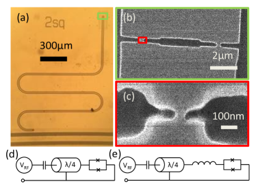
Two chips are fabricated from Nb films deposited according to the same recipe in separate sputter runs and labelled A and B. We discuss two resonators from each of these chips, one tunable and one bare resonator labelled Tune and Bare respectively. We refer to resonators by a combination of chip And resonator label e.g. ATune is the tunable resonator from chip A. chip A (B) has an area of 58 mm2 (44 mm2). Before deposition, chip B is dipped into HF for 10 s to remove a native oxide coating and then loaded into the sputter system and put under vacuum within 5-10 minutes. Quarter-wave (/4) resonators (see Fig. 1a) with an embedded superconducting loop at the grounded end of the resonator were patterned by electron beam lithography (EBL) (Fig. 1b) in the same lithography step as a microwave feed line. The resist pattern was transferred into the film by a reactive ion etch (RIE) process using a 2:1 ratio of SF6 to Ar, at 30 mbar and 30 W for 120 s. The RIE process additionally etches exposed Si to a depth of 500 nm, leaving areas with Nb raised above their surroundings. Resonators on chip B have a long constriction (100 m 1 m) embedded into the central conductor just before the SQUID. The narrow constriction create larger local fluctuating fields and increase the resonator coupling to spins in future devices Bienfait et al. (2016). The increased coupling comes at the cost of including a constriction which acts as a lumped element inductor reducing the inductance ratio between SQUID and resonator, which consequently reduces the resonator tunability.
The superconducting loop has two constrictions (see Fig. 1b and c): broad constrictions are defined in the initial EBL exposure and subsequently narrowed to 50 nm by Ne FIB milling, in which a beam of Ne ions, accelerated to 15 kV, mills through the Nb. A dose of 2 nCm-2 is used. Circuit diagrams of these devices are shown in Fig. 1 d (e) for Atune (BTune). On chip A, 21 out of 22 constrictions milled were still intact after narrowing to a dimension approaching the coherence length, suggesting a high yield for this part of the processing; see supplementary materials SI for statistical analysis on junction widths.
Resonators are measured at a temperature mK in a 3He cryostat with a heavily attenuated microwave in-line and a cryogenic high-electron-mobility transistor (HEMT) amplifier on the microwave out-line. The transmission of microwaves through the feed-line —to which the resonator is capacitively coupled— is measured using a Rohde & Schwarz ZNB8 vector network analyzer. Perpendicular magnetic fields are applied by a superconducting magnet connected to a precision current source (Keithley 2400 SourceMeter). Samples are enclosed in a brass box lined with Eccosorb CR-117, a microwave absorber, to reduce the number of quasiparticles excited by stray IR photons, which we have previously shown can have a significant effect on superconducting constrictions Burnett et al. (2017).
III Results
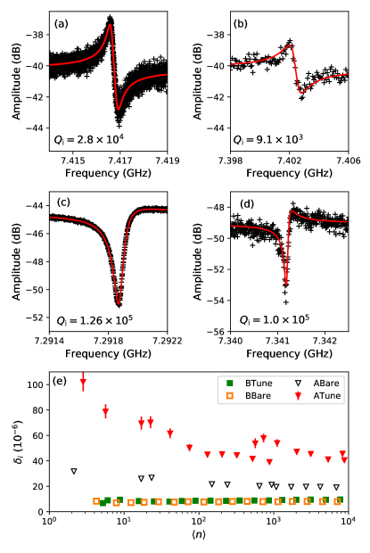
We first characterize the zero-field characteristics of the resonators on the two chips at the base temperature of the cryostat. In Fig. 2, we show the zero-field magnitude response of from ATune (Fig. 2 a) and BTune (Fig. 2 c) at an applied power of -106 dBm. Using a traceable fit routine Probst et al. (2015), based on fitting a circle to the resonance in the real–imaginary plane, we extract the resonator parameters (fits shown in red in Fig. 2). At an applied power of dBm ATune, ABare, BTune and BBare have internal quality factors , , and respectively (resonance notches of bare resonators are not shown). The biggest difference between zero-field quality factors is between the different films rather than between the bare and tunable resonators. This shows that at high drive power, the SQUIDs introduce minimal extra losses and that the losses are dominated by effects arising from the film quality. The asymmetry of the resonance of ATune (Fig. 2a, b) persists down to single-photon powers due to an impedance mismatch and this is fully captured by the fit routine. Fig. 2b, d shows that both ATune and BTune resonances are present at applied perpendicular fields approaching 0.5mT with resonance responses. We discuss resonator behaviour in an applied magnetic field later in the manuscript.
We measure the internal losses of all four resonators () as a function of the average photon number within the resonator (see Fig. 2 e). Resonators from film A show higher losses across all powers than resonators from film B irrespective of whether they are bare or tunable. Whilst ATune shows more losses than ABare and a greater increase in losses at low power, for film B the losses are approximately equal for BTune and BBare. We therefore attribute the difference in losses in film A to on-chip variation in film quality, as commonly seen in CPW resonators. Losses are dominated by losses associated with the film rather than losses introduced by the SQUID even in the single photon limit. The difference between films could be a result of the small recipe differences such as the HF dip for film B; however, the increased loss at high powers is indicative of increased conductor losses associated with the quality of superconducting films.
III.1 Tunability
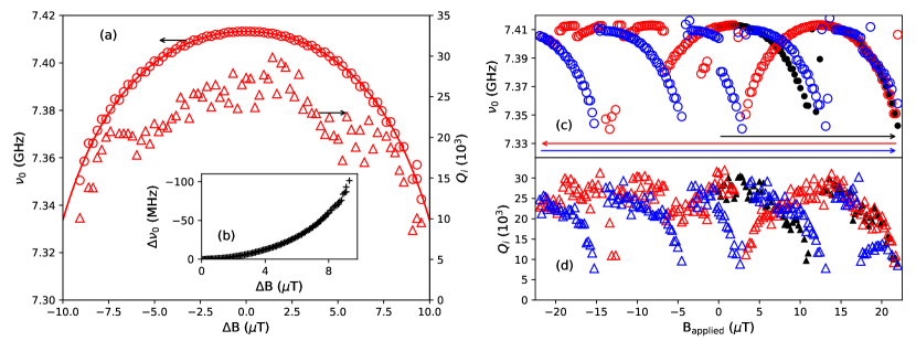
In order to study resonator tuning we examine ATune. Without a lumped element inductor, the tunable SQUID inductance is a greater fraction of the total inductance and so this resonator tunes more in frequency. We first study its behaviour in a small perpendicular magnetic field (T). Fig. 3 a shows a typical field sweep; this reveals the smooth tuning of the resonator towards lower frequencies as magnetic field amplitude is increased. The full range of frequency tuning is found to be 100 MHz, obtained by changing the applied perpendicular field by 10 T (see Fig. 3 b) 111Here, field has been changed in small (0.1 T) steps to approach maximal detuning whilst ensuring that the point of maximal detuning is not overshot before the sweep direction is reversed.. To analyse this behaviour, we start by assuming a Josephson-like sinusoidal current-phase relationship for the nano-constrictions since the length:width ratio of the constrictions shown in Fig. 1 c is approximately one Golubov et al. (2004). We therefore treat the superconducting loop as a DC-SQUID with a flux-tunable inductance Sandberg et al. (2008)
| (1) |
where is the zero-field critical current of the SQUID, is the frustration of the SQUID and is the flux quantum.
The total impedance of a transmission line terminated by a SQUID is given at frequency by
| (2) |
where is the length of the transmission line, is the impedance of the transmission line, the impedance of the SQUID and the speed of light in the transmission line where () is the capacitance (inductance) per unit length. is real at resonance and the resonant frequencies are therefore given by
| (3) |
which may be solved numerically. The fundamental resonant frequency may be expressed approximately [31] in terms of the total inductance and capacitance of the distributed resonator:
| (4) |
where is the inductance of the resonator excluding the SQUID, is the zero-field inductance of the SQUID. is the change of inductance of the SQUID with field which, from Eq. 1, is equal to . Assuming , an assumption which we examine further below, we can write
| (5) |
where and so that scales field to . The observed dependence of the resonator in Fig. 3 fits well with Eq. 5, allowing determination of and .
We next consider the relation between the field periodicity of the tuning behaviour and the flux quantum. SQUID behaviour is periodic in applied flux. The area of the SQUID loop in ATune is 0.3m2, so 10 T (the field required to maximally tune the resonator) corresponds to a flux . Assuming the tuning arises from the SQUID, the field required to maximally tune the resonator implies that the local flux density at the SQUID is much greater than the 10 T applied by the magnet. This indicates substantial flux focusing due to flux expulsion from the superconducting ground plane surrounding the resonators. We return to the topic of flux focusing later.
As ATune is tuned away from , is found to drop from its maximum value, 2.8104, to 1.0104 when maximally tuned. The same trend of decreasing with tuning is also seen in BTune. This phenomenon of decreasing with tuning has previously been observed and attributed to increasing thermal noise as the SQUID is tuned Palacios-Laloy et al. (2008) or increased dissipation caused by a sub-gap resistance Sandberg et al. (2008). An alternative explanation could be that dilute surface spins de Graaf et al. (2017) induce spectral broadening of the resonance lineshape by flux-noise-based frequency jitter in these flux-tunable resonators. However, even for the highest values of flux noise in Ref. 33, which correspond to 100, the corresponding frequency jitter would be too small to create sufficient spectral broadening to explain the drop in observed here. The source of these extra losses is the subject of ongoing work.
III.2 Hysteresis and Premature Switching
When tuning ATune over more than one period, as shown in Fig. 3c and d, a hysteretic behaviour is seen, similar to that previously reported in Al constriction SQUID resonators Levenson-Falk et al. (2011). In addition, frequency jumps are observed at values of tuning less than the maximum value (see for example the region between T and T). We attribute jumps at non-maximal tuning to flux trapping as the field is ramped up and down. The oscillations in the internal quality factor (Fig. 3d) follow the frequency tuning of the resonator, showing that the degradation in with magnetic field arises from the state of the SQUID and not from the properties of the resonator in a magnetic field.

The hysteretic tuning of the resonant frequency and internal quality factor may be explained by significant self-inductance of the superconducting SQUID loop. The SQUID has a characteristic parameter (where is the inductance of the loop and is the Josephson critical current). When , the SQUID behaviour becomes hysteretic with applied flux, as shown in Fig. 4a. The red path in Fig. 4b maps out the flux within the SQUID as the field is increased (assuming zero temperature, in the absence of fluctuations). At extremal points, the flux threading the SQUID exhibits discontinuous jumps as is ramped upwards, occurring periodically with a period of 2. At finite temperature, thermal fluctuations cause these jumps to occur at a temperature-dependent flux less than that at .
Using this 2 periodicity, we are able to calibrate local fields at our device and experimentally quantify flux focusing in these hysteretic devices. Jumps occur every 9.7 T (averaged over 4 consecutive jumps in Fig. 5), which corresponds to 0.016. Identifying the jumps as -periodic features, we infer a flux-focusing , where we have defined by . Significant flux focusing from superconducting ground planes has recently been investigated theoretically and experimentally in Ref. 35, where simulations gave . The extent of flux focusing is specific to device geometry; for example, features designed to trap flux can have large effects on .
The change in applied flux required to maximally tune the resonator frequency is determined by the value of the SQUID (see Fig. 4c). At finite temperature, the flux in the SQUID jumps before reaching the point of instability shown in Fig. 4, and so the experimentally measured jump positions provide a lower bound on . We thus infer that for our device. Using Eq. 1 and the fit parameter (which relates the inductance of the resonator and of the SQUID), we can calculate the expected tuning of the resonator in an applied magnetic field based on a sinusoidal current–phase relation (Fig. 4d). The smooth tuning shown in Fig. 3a (blue line in Fig. 4b,d) and jumps seen in Fig. 3c (red line in Fig. 4b,d) are qualitatively reproduced. The calculation, however, suggests that resonant frequencies should decrease significantly in the vicinity of hysteretic jumps due to the asymptote in at , whereas in practice these resonators tune by only of their untuned frequency. Numerical analysis Kim et al. (2015) based on Eq. 3 predicts such reduced tuning for resonators where the SQUID inductance or capacitance is a significant fraction of the total inductance or capacitance of the distributed resonator. We determine the untuned inductance of the SQUID to be approximately 10% of the total inductance of the distributed resonator (see supplementary materials SI for details), which in Ref. [36] is sufficient (even with small SQUID capacitance) to reduce the tuning of the resonator approaching to only around 30%. Additionally, asymmetry between junctions allows switching at smaller tuning than perfectly symmetric devices as the narrower junction becomes maximally biased (and hence switches) before the wider junction becomes maximally biased.
III.3 Magnetic field resilience
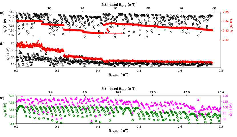
In Fig. 5, ATune (black markers), ABare (red markers) and BTune (green and magenta markers) are measured as the applied perpendicular magnetic field is increased from zero to 0.5 mT, which corresponds to a local field at the SQUID of 60 mT for chip A and 20 mT for chip B due to different flux focusing factors. The smaller size of chip B likely contributes to the smaller flux focusing factor.
The resonance responses and their fits at these fields are shown in Fig. 2b, c. Even at these perpendicular magnetic fields, the internal quality factor of ATune (BTune) is 103 () and the resonator remains tunable, demonstrating the field resilience of these devices. Indeed Fig. 5c shows that BTune retains a high quality factor right across the field range shown, even after tuning through 42 periods.
For ABare, and tune weakly and smoothly as the applied magnetic field is increased up to about 0.21 mT with the exception of abrupt drops in both and at four field values up to 0.2 mT (see Fig. 5). This step-like response of vs magnetic field is consistent with the formation of vortices on the superconducting resonator’s central conductor Nsanzineza and Plourde (2014). For ATune, modulates by a factor of about 5 with field as the resonator tunes (as previously shown in Fig. 3). In addition to the modulation with tuning, the maximum also drops with increasing applied field. The magnitude and field scale of this drop are similar to those of the bare resonator. The respective dependences for ATune and ABare are consistent with the maximum of the field-modulated in ATune being limited, as increases, by the same physics which causes the step-like reductions in for ABare. The similarity is even more clearly seen in , where the untuned resonant frequency of ATune jumps up at an applied field of 0.21 mT just as in the bare resonator. This suggests that not only does the nanoSQUID introduce minimal loss at zero applied field, the resonator’s field resilience is the limiting factor in the field performance of the device. This is also consistent with measurements of nanoSQUIDs fabricated from ultrathin niobium films successfully operating in parallel fields up to 7 T Chen et al. (2010). Our results are therefore promising for future generations of devices where SQUIDs are embedded within field-resilient resonators. Importantly, ATune operates at local fields comfortably above 30 mT (and BTune looks likely to also operate at such fields), the first clock transition of bismuth spins.
In the literature, resonator tuning is typically given in units of flux quanta. This means that there are no comparable results on field resilience of tunable resonators to which this device can be compared. Therefore, we believe that this study is the first report addressing the field resilience of tunable resonators.
IV Conclusions
In conclusion, we have embedded constriction nanoSQUIDs in Nb resonators, and shown that this device geometry results in a frequency tunable resonator with 100 MHz of tuning demonstrated in a 7.42 GHz resonator. We fabricate these devices from two Nb chips and show that the untuned quality factor of these resonators is limited by the bare resonator technology rather than embedding the SQUID, up to internal quality factors of — the highest quality factor SQUID-tunable resonator reported to date. These results are realised in two different resonators where one has high quality and the other is more tunable, however there is no fundamental trade-off being made between quality and tunability in these devices. By comparing the quality factors of tunable and bare resonators we demonstrate that the quality is determined by the superconducting films. The tunability differs due to different device geometries. We show that even these high quality factors are resonator-limited both at zero-field and applied perpendicular magnetic fields up to 0.5 mT and for resonator photon number from down to single photons at zero field. These resonators remain tunable at applied perpendicular fields of 0.5 mT and retain an untuned quality factor . The devices presented here compare favourably with the highest quality tunable resonators previously reported Vissers et al. (2015). Those resonators tune due to kinetic inductance shifts from DC currents and achieve high-power quality factors of ; there are no reports of low power operation.
A number of modifications to the device and measurement setup may straightforwardly be made to improve field resilience, specifically: operating the device in parallel fields (which tune spins to the clock transition without applying large fields to the resonator), modifying the device design by the addition of anti-dots Bothner et al. (2011), patterning the whole ground-plane Graaf et al. (2012) and/or the use of resonator designs inherently more robust to external field Samkharadze et al. (2016); Bothner et al. (2011); Graaf et al. (2012). The nanoSQUIDs allow us to measure the local magnetic field around the resonators and we find that the local fields are 30–120 time greater than the applied fields meaning these modifications should straightforwardly significantly improve field resilience.
These resonators hold great promise for future hybrid quantum system applications. For example, a tunable resonator operating at 27mT coupled to Bi spins in Si could address spins at their clock transition. The resonator could be tuned into resonance with the spins, and ESR pulse sequences applied, before the resonator is tuned away from the spins in frequency, allowing the long-coherence-time spins to store quantum information, unperturbed by the resonators.
V Acknowledgements
The authors thank E. J. Romans, A. Blois, S. Probst, P. Bertet, C. W. Zollitsch for useful discussions. This project has received funding from the European Union s Horizon 2020 research and innovation programme under the Marie Sklodowska-Curie grant agreement No 705713 QUINTESSENS (E. D.-F.), the European Community’s Seventh Framework Programme through grant agreement No. 279781 (ASCENT) (J.M.), Carl Zeiss Semiconductor Manufacturing (O. W. K.) and the U.K. Engineering and Physical Sciences Research Council, Grant Numbers EP/J017329/1 (J. C. F.), EP/K024701/1 and EP/H005544/1 (O. W. K. and P. A. W.), EP/P510270/1 (O. W. K).
References
- Bienfait et al. (2016) A Bienfait, JJ Pla, Y Kubo, X Zhou, M Stern, CC Lo, CD Weis, T Schenkel, D Vion, D Esteve, JJL Morton, and P Bertet, Controlling spin relaxation with a cavity, Nature 531, 74 (2016).
- Kubo et al. (2010) Y Kubo, FR Ong, Patrice Bertet, Denis Vion, V Jacques, D Zheng, A Dréau, J-F Roch, Alexia Auffèves, Fedor Jelezko, Wrachtrup J, MF Barthe, P Bergonzo, and D Esteve, Strong coupling of a spin ensemble to a superconducting resonator, Physical Review Letters 105, 140502 (2010).
- Probst et al. (2013) S Probst, H Rotzinger, S Wünsch, P Jung, M Jerger, M Siegel, AV Ustinov, and PA Bushev, Anisotropic rare-earth spin ensemble strongly coupled to a superconducting resonator, Physical Review Letters 110, 157001 (2013).
- Huebl et al. (2013) H Huebl, CW Zollitsch, J Lotze, F Hocke, M Greifenstein, A Marx, R Gross, and STB Goennenwein, High cooperativity in coupled microwave resonator ferrimagnetic insulator hybrids, Physical Review Letters 111, 127003 (2013).
- Abdurakhimov et al. (2018) LV Abdurakhimov, S Khan, NA Panjwani, JD Breeze, S Seki, Y Tokura, JJL Morton, and H Kurebayashi, Strong coupling between magnons in a chiral magnetic insulator and microwave cavity photons, arXiv preprint arXiv:1802.07113 (2018).
- Mi et al. (2017) Xiao Mi, JV Cady, DM Zajac, PW Deelman, and JR Petta, Strong coupling of a single electron in silicon to a microwave photon, Science 355, 156–158 (2017).
- Grèzes et al. (2016) C Grèzes, Y Kubo, B Julsgaard, T Umeda, J Isoya, H Sumiya, H Abe, S Onoda, T Ohshima, K Nakamura, I Diniz, A Auffeves, V Jacques, J-F Roch, D Vion, D Esteve, K Moelmer, and P Bertet, Towards a spin-ensemble quantum memory for superconducting qubits, Comptes Rendus Physique 17, 693–704 (2016).
- Larsen et al. (2015) TW Larsen, KD Petersson, F Kuemmeth, TS Jespersen, P Krogstrup, J Nygård, and CM Marcus, Semiconductor-nanowire-based superconducting qubit, Phyiscal Review Letters 115, 127001 (2015).
- Yan et al. (2016) F Yan, S Gustavsson, A Kamal, J Birenbaum, AP Sears, D Hover, TJ Gudmundsen, D Rosenberg, G Samach, S Weber, JL Yoder, TP Orlando, J Clarke, AJ Kerman, and WD Oliver, The flux qubit revisited to enhance coherence and reproducibility, Nature Communications 7, 12964 (2016).
- Dunsworth et al. (2017) A Dunsworth, A Megrant, C Quintana, Z Chen, R Barends, B Burkett, B Foxen, Y Chen, B Chiaro, A Fowler, R Graff, E Jeffrey, J Kelly, E Lucero, JY Mutus, M Neeley, C Neill, P Roushan, D Sank, A Vainsencher, J Wenner, TC White, and JM Martinis, Characterization and reduction of capacitive loss induced by sub-micron josephson junction fabrication in superconducting qubits, Applied Physics Letters 111, 022601 (2017).
- Blum et al. (2015) S Blum, C O’Brien, N Lauk, P Bushev, M Fleischhauer, and G Morigi, Interfacing microwave qubits and optical photons via spin ensembles, Phyiscal Review A 91, 033834 (2015).
- Burnett et al. (2014) J Burnett, L Faoro, I Wisby, VL Gurtovoi, AV Chernykh, GM Mikhailov, VA Tulin, R Shaikhaidarov, V Antonov, PJ Meeson, AY Tzalenchuk, and T Lindström, Evidence for interacting two-level systems from the 1/f noise of a superconducting resonator, Nature Communications 5, 4119 (2014).
- Barends et al. (2014) R Barends, J Kelly, A Megrant, A Veitia, D Sank, E Jeffrey, TC White, J Mutus, AG Fowler, B Campbell, Y Chen, Z Chen, B Chiaro, A Dunsworth, C Neill, P O’Malley, P Roushan, A Vainsencher, J Wenner, AN Korotkov, Cleland AN, and JM Martinis, Superconducting quantum circuits at the surface code threshold for fault tolerance, Nature 508, 500–503 (2014).
- Megrant et al. (2012) A Megrant, C Neill, R Barends, B Chiaro, Yu Chen, L Feigl, J Kelly, Erik Lucero, Matteo Mariantoni, PJJ O’Malley, D Sank, A Vainsencher, J Wenner, TC White, Y Yin, J Zhao, Palmstrøm CJ, John M Martinis, and AN Cleland, Planar superconducting resonators with internal quality factors above one million, Applied Physics Letters 100, 113510 (2012).
- Palacios-Laloy et al. (2008) A Palacios-Laloy, F Nguyen, F Mallet, P Bertet, D Vion, and D Esteve, Tunable resonators for quantum circuits, Journal of Low Temperature Physics 151, 1034–1042 (2008).
- Sandberg et al. (2008) M Sandberg, CM Wilson, F Persson, T Bauch, G Johansson, V Shumeiko, T Duty, and P Delsing, Tuning the field in a microwave resonator faster than the photon lifetime, Applied Physics Letters 92, 203501 (2008).
- Levenson-Falk et al. (2011) EM Levenson-Falk, R Vijay, and I Siddiqi, Nonlinear microwave response of aluminum weak-link josephson oscillators, Applied Physics Letters 98, 3115 (2011).
- Adamyan et al. (2016) AA Adamyan, SE Kubatkin, and AV Danilov, Tunable superconducting microstrip resonators, Applied Physics Letters 108, 172601 (2016).
- Asfaw et al. (2017) AT Asfaw, AJ Sigillito, AM Tyryshkin, T Schenkel, and SA Lyon, Multi-frequency spin manipulation using rapidly tunable superconducting coplanar waveguide microresonators, Applied Physics Letters 111, 032601 (2017).
- Granata and Vettoliere (2016) C Granata and A Vettoliere, Nano superconducting quantum interference device: A powerful tool for nanoscale investigations, Physics Reports 614, 1–69 (2016).
- Martínez-Pérez et al. (2017) MJ Martínez-Pérez, R Kleiner, and D Koelle, NanoSQUIDs Applied to the Investigation of Small Magnetic Systems, in The Oxford Handbook of Small Superconductors (OUP, 2017).
- Schwarz et al. (2013) T Schwarz, J Nagel, R Wölbing, M Kemmler, R Kleiner, and D Koelle, Low-noise nano superconducting quantum interference device operating in tesla magnetic fields, ACS Nano 7, 844–850 (2013).
- Hao et al. (2009) L Hao, D C Cox, and J C Gallop, Characteristics of focused ion beam nanoscale josephson devices, Superconductor Science and Technology 22, 064011 (2009).
- Jenkins et al. (2014) MD Jenkins, U Naether, M Ciria, J Sesé, J Atkinson, C Sánchez-Azqueta, E del Barco, J Majer, D Zueco, and F Luis, Nanoscale constrictions in superconducting coplanar waveguide resonators, Applied Physics Letters 105, 162601 (2014).
- Burnett et al. (2017) J Burnett, J Sagar, OW Kennedy, PA Warburton, and JC Fenton, Low-loss superconducting nanowire circuits using a neon focused ion beam, Physical Review Applied 8, 014039 (2017).
- Meservey and Schwartz (1969) R Meservey and BB Schwartz, Equilibrium properties: Comparison of experimental results with predictions of the BCS theory, Tech. Rep. (Massachusetts Inst. of Tech., Cambridge, 1969).
- (27) See Supplemental Material at … for details on further statistics on junction dimensions, measurements on additional devices and calculations of resonator and SQUID inductance. .
- Probst et al. (2015) S Probst, FB Song, PA Bushev, AV Ustinov, and M Weides, Efficient and robust analysis of complex scattering data under noise in microwave resonators, Review of Scientific Instruments 86, 024706 (2015).
- Note (1) Here, field has been changed in small (0.1 T) steps to approach maximal detuning whilst ensuring that the point of maximal detuning is not overshot before the sweep direction is reversed.
- Golubov et al. (2004) AA Golubov, MY Kupriyanov, and E Il’Ichev, The current-phase relation in josephson junctions, Reviews of modern physics 76, 411 (2004).
- Jones et al. (2013) PJ Jones, JAM Huhtamäki, J Salmilehto, KY Tan, and M Möttönen, Tunable electromagnetic environment for superconducting quantum bits, Scientific Reports 3, 1987 (2013).
- de Graaf et al. (2017) SE de Graaf, AA Adamyan, T Lindström, D Erts, SE Kubatkin, AYa Tzalenchuk, and AV Danilov, Direct Identification of Dilute Surface Spins on : Origin of Flux Noise in Quantum Circuits, Phyiscal Review Letters 118, 057703 (2017).
- Ithier et al. (2005) G Ithier, E Collin, P Joyez, PJ Meeson, D Vion, D Esteve, F Chiarello, A Shnirman, Y Makhlin, J Schriefl, and G Schön, Decoherence in a superconducting quantum bit circuit, Phyiscal Review B 72, 134519 (2005).
- Tinkham (2004) M Tinkham, Introduction to superconductivity (Courier Corporation, 2004).
- Bothner et al. (2017) Daniel Bothner, Dominik Wiedmaier, Benedikt Ferdinand, Reinhold Kleiner, and Dieter Koelle, Improving superconducting resonators in magnetic fields by reduced field focussing and engineered flux screening, Physical Review Applied 8, 034025 (2017).
- Kim et al. (2015) Eun-jong Kim, JR Johansson, and Franco Nori, Circuit analog of quadratic optomechanics, Physical Review A 91, 033835 (2015).
- Nsanzineza and Plourde (2014) I. Nsanzineza and B. L. T. Plourde, Trapping a single vortex and reducing quasiparticles in a superconducting resonator, Phyiscal Review Letters 113, 117002 (2014).
- Chen et al. (2010) Lei Chen, Wolfgang Wernsdorfer, Christos Lampropoulos, George Christou, and Irinel Chiorescu, On-chip SQUID measurements in the presence of high magnetic fields, Nanotechnology 21, 405504 (2010).
- Vissers et al. (2015) Michael R Vissers, Johannes Hubmayr, Martin Sandberg, Saptarshi Chaudhuri, Clint Bockstiegel, and Jiansong Gao, Frequency-tunable superconducting resonators via nonlinear kinetic inductance, Applied Physics Letters 107, 062601 (2015).
- Bothner et al. (2011) D Bothner, T Gaber, M Kemmler, D Koelle, and R Kleiner, Improving the performance of superconducting microwave resonators in magnetic fields, Applied Physics Letters 98, 102504 (2011).
- Graaf et al. (2012) SE de Graaf, AV Danilov, Astghik Adamyan, Thilo Bauch, and SE Kubatkin, Magnetic field resilient superconducting fractal resonators for coupling to free spins, Journal of Applied Physics 112, 123905 (2012).
- Samkharadze et al. (2016) N Samkharadze, A Bruno, P Scarlino, G Zheng, DP DiVincenzo, L DiCarlo, and LMK Vandersypen, High-kinetic-inductance superconducting nanowire resonators for circuit qed in a magnetic field, Physical Review Applied 5, 044004 (2016).