Over-the-Air Time Synchronization for URLLC: Requirements, Challenges and Possible Enablers
Abstract
Ultra-reliable and low-latency communications (URLLC) is an emerging feature in 5G and beyond wireless systems, which is introduced to support stringent latency and reliability requirements of mission-critical industrial applications. In many potential applications, multiple sensors/actuators collaborate and require isochronous operation with strict and bounded jitter, e.g., . To this end, network time synchronization becomes crucial for real-time and isochronous communication between a controller and the sensors/actuators. In this paper, we look at different applications in factory automation and smart grids to reveal the requirements of device-level time synchronization and the challenges in extending the high-granularity timing information to the devices. Also, we identify the potential over-the-air synchronization mechanisms in 5G radio interface, and discuss the needed enhancements to meet the jitter constraints of time-sensitive URLLC applications.
I Introduction
In 5G and beyond wireless systems, ultra-reliable and low-latency communications (URLLC) feature is focused on time-sensitive applications originating for vertical industries such as industrial automation, smart grids, tactile internet, automotive and more. There can be many use cases within a single industry while each use case presents a different set of requirements and challenges. For instance in industrial automation, factory automation is one of the most challenging use case for URLLC that requires deterministic communication with bounded reliability and latency. In addition, factory automation often entails real-time interactions among multiple entities, and ultra-tight synchronization of the entities with a common time reference is need to complete manufacturing. As there are many existing industrial wired and wireless systems [1], 5G radio access requires a new time synchronization service for enabling URLLC in heterogeneous industrial setups.
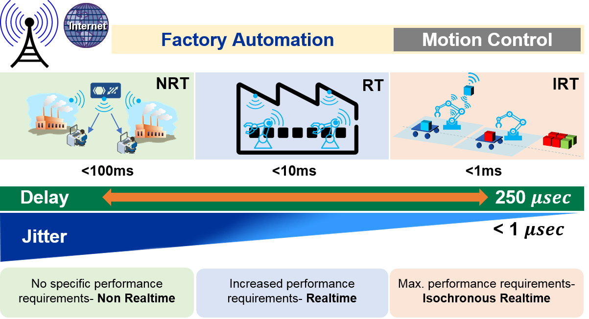
In factory automation, when classifying applications regarding their timeliness and reliability requirements, there can be three main application classes; i) non real-time (NRT) or soft real-time, ii) hard real-time (RT), and iii) isochronous real-time (IRT) as illustrated in Fig. 1. Most of the applications in process automation belong to NRT or soft real-time class. Whereas the discrete manufacturing applications, which rely on robotics and belt conveyers for assembly, picking, welding and palletizing, execute tasks in a timely and sequential manner [2]. These jobs involve tightly synchronized real-time cooperation among multiple robots and the production line. To generalize, discrete manufacturing applications are a part of hard RT or IRT class; that is, given deadlines must be met strictly or deadlines must be satisfied along with the constraints on jitter. In this regard, IEEE 802.1 time-sensitive networking (TSN) standards specify strict performance requirements: cycle time, reliability and jitter i.e., allowed variations in delay.
To satisfy the needed determinism and synchronism in industrial automation, 5G URLLC requires innovative solutions. Several radio access solutions are under consideration to meet the latency and reliability requirements (e.g., see [3, 4]). However, RT and IRT communication with tight jitter constraint requires accurate time instants on a common time base at the device level. In a factory floor, the devices might belong to different base stations (BS) or even to different domains in case of coexisting industrial networks. To get a common time reference for the devices would require over-the-air (OTA) synchronization mechanisms beyond timing advance-based frame alignment between UEs and BS. While, OTA synchronization procedures for LTE-TDD and radio coordination in small cells are limited to synchronization of BSs only [5]. To enable time synchronization for the devices, a recent LTE URLLC work item includes that the synchronization shall be standardized for LTE Rel-15 [6].
In this article, we highlight the drivers and challenges of ultra-tight time synchronization in factory automation and smart grids. We identify the opportunities in the LTE air interface to enable OTA synchronization solutions. In particular, we summarize how these signaling parameters can be enhanced and grouped together to extend high-granularity timing information to the devices.
II Preliminaries
II-A Oscillator, Clock, Synchronization, Accuracy, Jitter etc.
Synchronization types. ITU-T G.8260 defines three types of synchronization:
-
•
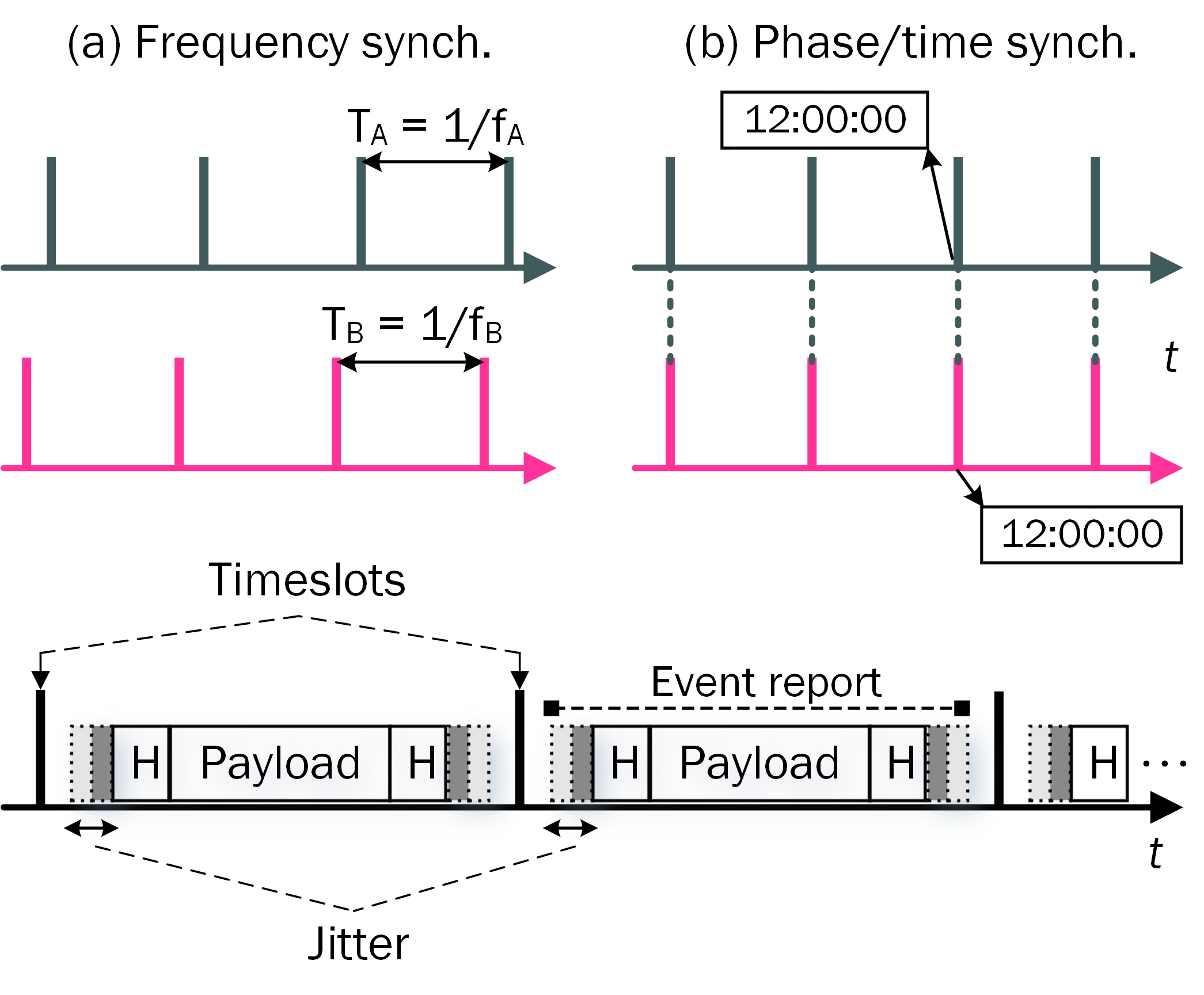
Frequency: two systems are frequency synchronized when their significant instants occur at the same rate.
-
•
Phase: in phase synchronized systems, the rising edges occur at the same time, e.g., the point in time when the time slot of a frame is to be generated.
-
•
Time: time synchronization is the distribution of an absolute time reference to a set of real-time clocks. The synchronized clocks have a common epoch timescale. Note that distribution of time synchronization is a way of achieving phase synchronization.
The synchronization types are illustrated in Fig. 2. As we focus on time-aware URLLC applications, the further discussion is confined to time synchronization.
What causes time de-synchronization? A device maintains the sense of time–a clock–by counting the pulses of an internal crystal oscillator [7]. But, there is an inherent inaccuracy in frequency (causing clock skew) and phase of the crystal oscillator. The inaccuracy is influenced by the operating conditions and aging (resulting in clock drift). As a result, the devices deviate from a reference clock after a synchronization epoch [8].
Jitter. Implies the packet delay variations from defined ideal position in time (Fig. 2). Many closed-loop control applications are intolerant to such delay variations.
II-B Time Synchronization in Industrial Networks
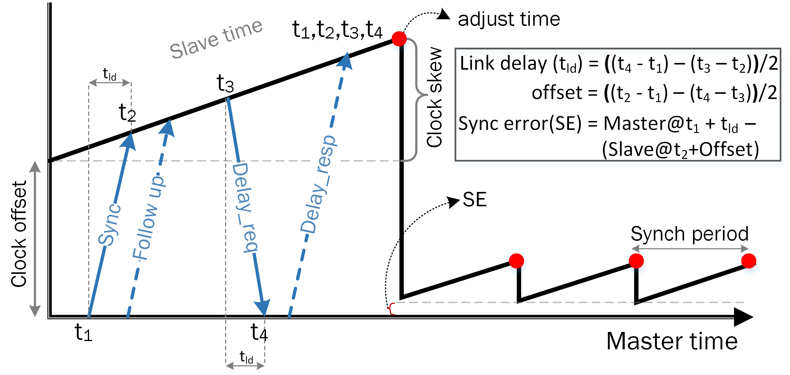
Networked distributed measurement and control systems (e.g., bus systems and factory automation setups) are reliant on IEEE 1588 precision time protocol (PTP) [9] for real-time and isochronous transmissions. IEEE 1588 is a master-slave protocol designed to synchronize real-time clocks in the order of sub-microseconds in packet-based networks. Fig.3 shows the synchronization procedure, which is based on the timestamping of the exchanged signaling messages to find time offset of a device from the master clock.
Ethernet-based automation networks, PROFINET and IEEE 802.1 TSN, use IEEE 1588 variants (PTP profile) to ensure determinism. The 802.1 TSN task group [10] is developing standards to support time-sensitive applications, for industries like factory automation and automotive, over IEEE 802 networks. TSN contains a series of standards related to ultra reliability, low latency and resource management aspects while TSN 802.1AS is the standard for transport of precise timing and synchronization [11]. Note that Wi-Fi TimeSync also includes an extension of 802.1AS [12].
III Drivers for Ultra-Tight Synchronization and Requirements
Two important use cases of URLLC are industrial factory automation and smart grids [13]. These use cases have strict jitter requirements among devices as we discuss next.
III-A Industrial Factory Automation or Automation Control
In factory automation, closed-loop control applications–robot manufacturing, round table production, machine tools, packaging and printing etc.–are the main URLLC targets. In these applications, the need for ultra-tight synchronization is driven by real-time and time-slotted communication, and isochronous task execution.
Real-time communication. A typical closed-loop control cycle consists of a downlink transaction to a set of sensors periodically, which is followed by uplink responses by the sensors to the controller. The control events are executed within a cycle time and may occur isochronously. Cycle time is the time from the transmission of a command by the controller to the reception of its response from the devices. TSN [11] specifies stringent end-to-end latency and reliability constraints on each transaction i.e., it must be completed within a cycle time with reliability. Furthermore, a jitter constraint of is imposed on the delivery of responses which requires better than synchronization accuracy among devices. These requirements are also endorsed by 3GPP [13]. Any violation of latency and jitter in control commands can damage the production line and cause the safety issues.
Multi-robot cooperation–isochronous real-time. In motion control applications–mobilizing a fleet of tractors, symmetrical welding and polishing in the automobile production line–a group of robots collaborate to execute meticulously sequenced functions. A critical requirement to carry out these cooperative actions is synchronous task execution, which requires accurate time base across the collaborating entities. Therefore, when a controller sends a command to the robots to act at a specific time instant (isochronously), the robots should act/respond in less than . A lag in action may cause damages or inefficient production.
Time-slotted communication. To transport packets with bounded delays in RT traffic, time-slotted communication is an effective mechanism. Existing industrial wired and wireless networks implement a variant of time-slotted communication. It requires perfect time synchronization as any timing error leads to the overlap of time slots among the devices, which disrupts the communication reliability.
In monitoring applications, the time information must be embedded into the sensory data for operations such as data fusion. Thus, the collaborating sensors must be synchronized.
III-B Smart Grids
The traditional power grid is rapidly evolving to a smart grid through the automation of control and monitoring functions. To support this evolution, a cost-effective wireless communication infrastructure with wide-area coverage and high performance is needed. 5G offers the needed coverage while the performance requirements are application dependent, hence, needing further study. Three main application areas are fault protection, control, and monitoring and diagnostics [14].
Fault protection. High-speed communication of measurements between the two points of a transmission line can detect a fault using a line differential protection solution [14]. In line differential protection, two relay devices periodically sample the electric current in a section of distribution or transmission line, and exchange this information with each other. In case of a fault, the relays differ in measurements and can trigger a trip command to the breaker. Fault protection has the most stringent performance requirement: reliability and latency . In addition, the protection algorithm is effective if the relays are tightly synchronized (i.e., ).
Control and grid automation. In evolving power grids, with high penetration of renewable resources at various power output, we need new control and optimization mechanisms at both the transmission and distribution levels. The key control challenge is to match power-supply and -demand within acceptable voltage and frequency regulations. It demands for innovative centralized or decentralized control strategies based on fine-grained information of measured electrical values (e.g., voltage, power, frequency) of the load and the source. The difference in control actions impose different reliability and latency requirements. However, the performance requirements for control tasks are relaxed as compared to fault protection; reliability and latency while time synchronization accuracy is also less critical.
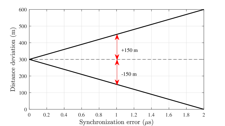
Monitoring and diagnostics. Wide-area monitoring and diagnostics requires ultra-tight synchronization. For instance, the phasor measurement units (PMU) in electricity distribution systems, deployed along the electricity line, are used for measuring the electrical value for fault detection. When a fault occurs, the fault location generates two electric waves towards the both ends. The two PMUs, acting as UEs, at both end of the electricity line detect the waves by the change in monitored parameters and record the time of detection. A monitoring system can estimate the fault location based on the reported time information given that the PMUs are perfectly synchronized. In most cases, synchronization accuracy of less than is required to keep the uncertainty in fault location below (see Fig. 4). While, the reliability and latency requirements are relaxed for the monitoring; and .
IV Challenges
IV-A Heterogeneity of Industrial Networks/Standards
URLLC can satisfy the requirements of most of the process and factory automation applications. However, it can not replace the existing industrial wired (e.g., industrial field bus, Ethernet of plant automation (EPA), Powerlink, Profinet) and wireless (e.g., WirelessHART, ISA 100.11a, WIA-PA111Wireless Networks for Industrial Automation-Process Automation: targeting reliability and latency. , WIA-FA222Wireless Networks for Industrial Automation-Factory Automation: fulfills reliability and latency. ) communication systems completely, at once or in a short time. Two main reasons behind this are: 1) updating the complete communication infrastructure is not cost-effective, 2) lack of trust and/or unsuitability of replacing the existing wired system in critical manufacturing cells with wireless systems. As a result, a coexistence between the traditional wired/wireless networks and URLLC is a likely scenario that would give a heterogeneous character to industrial networks.
Synchronization requisites. Owing to different requirements of industrial applications and different precision, resolution and stability of clocks running on the field devices, there are various existing synchronization solutions [9]. For the current coexisting wired-wireless networks, 802.1 AS-2011 [11] offers accurate time synchronization. If the devices from heterogeneous domains (wired, traditional wireless and URLLC) need to collaborate and complete the production, cross-domain synchronization among heterogeneous industrial networks will be essential.
Relative vs absolute time synchronization. For real-time communication, each industrial control entity should maintain a local clock to execute received commands at deterministic time instants. It works well under relative synchronization of the nodes with the controller. However, when multiple devices from different domains must operate concurrently, an absolute time synchronization among the devices will be mandatory. Hence, it is crucial that the devices are synchronized to an absolute time reference (e.g., UTC time) to perform coordinated operations.
Synchronization cases. The need of absolute time base at UEs arises from following situations.
-
•
URLLC domain: In a URLLC network, it is plausible that the devices connected to different BSs may require absolute time synchronization to execute an operation synchronously. Therefore, to establish and maintain synchronization among the devices, the BSs must also be synchronized.
-
•
Heterogeneous domain: The time-sensitive devices might also belong to heterogeneous domains. For instance, an old wired device might need to perform a task synchronously with a new wireless device. As a result, it is not sufficient for the devices to synchronize with their respective controllers.
Accordingly the network synchronization architecture in a heterogeneous setup, must support synchronization among devices associated to i) a single BS, ii) different BSs, and iii) different domains (e.g., URLLC domain and local domain comprising traditional industrial networks.)
IV-B Time Synchronization in Smart Grids
In today’s smart grids, wired communication is often used for the applications discussed in Sec. III-B. The synchronization among the measurement and control units, within a substation, is often maintained using IEEE 1588 or similar protocols. These protocols distribute the reference time, often acquired from GPS clocks, to the devices. To replace the wired infrastructure with 5G URLLC, a 5G network-based synchronization solution is required where only BSs may need to acquire time from GPS clocks. A built-in timing service of the wireless infrastructure can be cost-effective and it can avoid GPS vulnerabilities (e.g., jamming, signal reception). However, the challenge is to establish synchronization at the device level, which thus far is available to the BS level with limited accuracy (see Sec. IV-D).
IV-C GPS for Reference Time
GPS can align bases stations to a common time reference, however, GPS signal is not always available in e.g., indoor deployments, places with high constructions around and bad weather. The additional cost for GPS-based solution is also of a concern. For instance, in indoor industrial settings, the GPS antenna must be installed outdoors to ensure proper signal reception. Moreover, a feeder cable from the antenna to the receiver is required, along with an amplifier if the feeder cable is too long. To avoid GPS based solution, 5G network need to be upgraded to distribute the reference time to BSs. In addition, 5G network can be considered stable, adaptive and scalable as compared to wired/GPS solutions. However, the challenge is to devise OTA synchronization mechanisms to synchronization UEs to an absolute time through BS such that the devices are synchronized with each other.
IV-D Limitations of OTA Synchronization Solutions in LTE
| Application | Phase/Time Sync. | Note |
| LTE-FDD | N/A | - |
| LTE-TDD | cell radius | |
| cell radius | ||
| LTE-MBMS | intercell time difference | |
| LTE-Advanced | e.g., eICIC, CoMP444Coordinated multipoint (CoMP) and enhanced intercell interference coordination (eICIC) are interference coordination mechanisms. CoMP includes: joint transmission/reception, coordinated beamforming, dynamic point selection, and dynamic point blanking. | |
In LTE, the distribution of accurate timing reference is limited up to radio BS level for LTE-TDD to avoid interference among adjacent cells. Meanwhile, the small cell deployments and the benefits of radio coordination features therein is now increasing the demands for accurate synchronization of BSs. Examples of radio coordination features are enhanced intercell interference coordination (eICIC) and coordinated multipoint (CoMP). Table 3 summarize the synchronization needs in LTE.
Radio interface based synchronization. The current solutions, avoiding GPS- or backhaul network-based solutions, are focused on radio interface based synchronization (RIBS)-based OTA mechanisms. In particular, the first solution uses network listening of the reference signals from neighboring BSs [15]. However, the accuracy target is and the impact of propagation delay on synchronization accuracy is not considered. As the new interference coordination features in small cells require high synchronization accuracy, new RIBS-based solutions for intercell synchronization are under consideration in [16], e.g.,
-
•
Exchanging the reference signals (like IEEE 1588) between the neighboring base stations, which allow to calculate the propagation delay.
-
•
Listening of reference signals from neighboring BSs by a target small cell, and compensating the propagation delay measured by a UE using timing advance (TA) while assuming negligible propagation delay between the UE and the target small cell.
Implications for URLLC. The current activities in 3GPP are limited to intercell time synchronization while the tightest synchronization target among the base stations is . The industrial automation and smart grid applications require the same order of jitter however among the collaborating UEs. If the UEs belong to the same BS, we need an OTA synchronization mechanism that can accurately synchronize UEs to the BS. However, achieving synchronization among UEs is challenging if collaborating UEs belong to different BSs. This is because the time alignment error between the base stations and the expected error in OTA synchronization procedure to distribute time to UEs will add up. Therefore, for URLLC applications, the synchronization among BSs must be tight to achieve better synchronization at the device level.
V Enablers for OTA Synchronization
In this section, we explore the existing signaling parameters in LTE that could be potential enablers of achieving ultra-tight synchronization for URLLC. Also, we discuss how these features could lead to a new synchronization architecture.
V-A 3GPP and OTA Time Synchronization
TA Enhancement. Timing advance (TA) advances or retards the uplink transmissions of UEs in time relative to the distance-dependent propagation delay from the serving BS. A BS estimates the UE-BS propagation delay and issues TA updates to the UE in order to ensure that the uplink transmissions of all UEs are synchronized. In this way, the uplink collisions due to changing propagation delays are mitigated.
TA negotiation occurs during network access and connected states. At network access, TA value is estimated at BS from the network access request sent by UE. If the request is successful, the BS sends a TA command in random access response with value where . The TA command directs the UE to transmit its uplink frame by multiples of seconds, i.e., , before the start of the corresponding downlink frame, where is the sampling period. In connected state, TA is negotiated with periodic MAC control messages–to maintain BS-UE connection–which adjust the uplink timing of a UE relative to its current timing. It is value i.e., while each command adjusts the UE’s current uplink timing by seconds. The frequency of TA command is configurable as {500, 750, 1280, 1920, 2560, 5120, 10240}, which corresponds to the maximum number of subframes sent in between two TAs. As the subframes are consecutive and each subframe is , the timer duration can be interpreted as the number of milliseconds and offers a trade-off between the accuracy of transmissions’ alignment and the network load.
Note that is the basic unit of time in LTE, which is equal to . Due to discrete nature of TA (multiple of ), the propagation delay adjustment at UE is subject to an error of –half of the TA step. In addition, the delay estimation error at the BS is also affected by the multipath propagation especially in harsh channel conditions. The error could be large if the wrong TA bin is selected due to random error. Therefore, TA enhancement is required to get better synchronization accuracy.
SIB16 Enhancement. System information (SI) is an essential aspect of LTE air interface, which is transmitted by BS over broadcast control channel (BCCH) [17]. SI is comprised of a static and dynamic parts termed as master information block (MIB) and system information blocks (SIB), respectively. MIB contains frequently transmitted essential parameters needed to acquire cell information such as system bandwidth, system frame number, and physical hybrid-ARQ indicator channel configuration. It is carried on BCH transport channel and transmitted by physical broadcast channel (PBCH) every . All SIBs except SIB1 are scheduled dynamically. SIB1 contains information including; cell access restrictions, cell selection information and scheduling of other SIBS. Unlike MIB, SIBs are carried on DL-SH and transmitted on physical downlink shared channel (PDSCH). SIB1 configures the SI-window length and transmission periodicity of the SI messages. Although SIB1 is transmitted with a fixed schedule of , the resource allocation of PDSCH carrying all SIBs is dynamic. The resource allocation of PDSCH transmissions is indicated by downlink control information message, which is transmitted on physical downlink control channel (PDCCH).
In time-aware applications, a UE can get a common time reference (UTC and GPS) contained in SIB16. However, time information in SIB16 has limited granularity (i.e., ). To enable high accuracy synchronization service for URLLC applications, the granularity of SIB16 needs to be enhanced to or level.
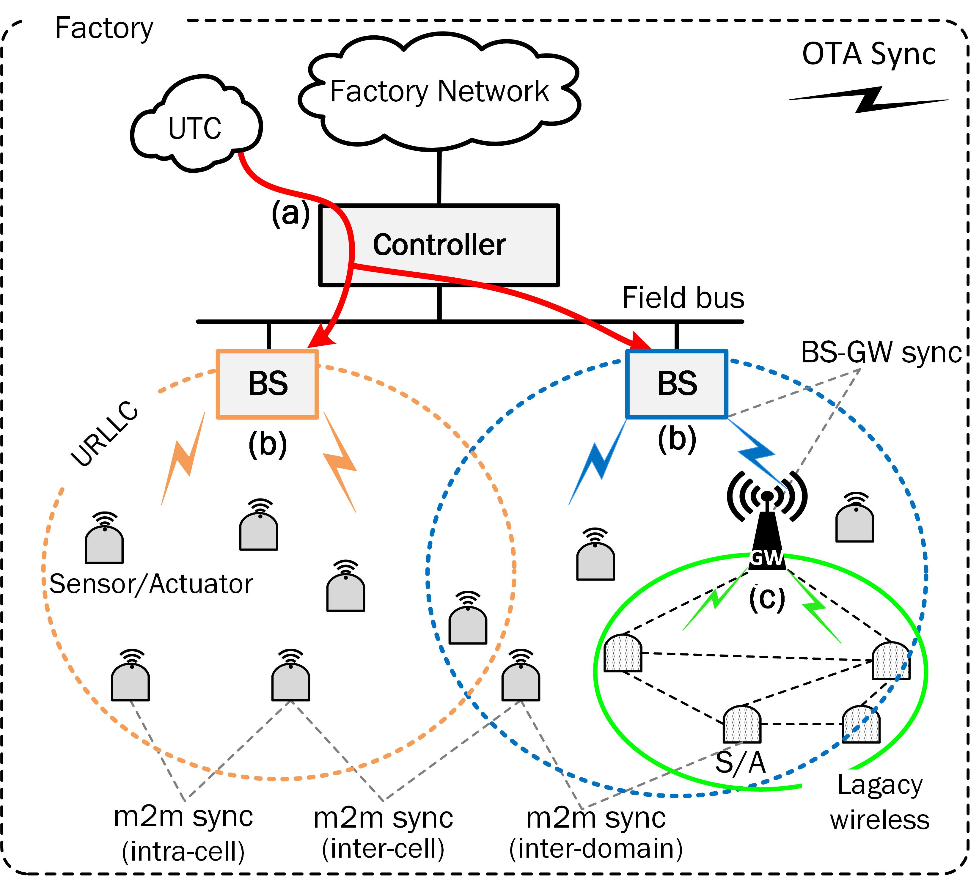
V-B New Synchronization Architecture
Considering emerging heterogeneity of industrial networks, a new ultra-tight synchronization architecture should provide: a) a flexible infrastructure for reference time, b) the absolute synchronization among devices. The 5G base stations can be used to provide time reference inside the URLLC domain and to the devices accessed via gateway. In this respect, each base station acts as a master clock while UEs/GWs as slave clocks. An example of such architecture is depicted in Fig. 5, where the flow of time reference in an heterogeneous industrial network setting is as follows:
-
•
Base stations acquire the reference time from a common source and act as master clocks for their associated devices.
-
•
GW/URLLC devices acquire the reference time from base stations using OTA time synchronization procedure. While the GW acts as a master clock to its local domain and distributes time to the devices.
Accordingly, with already discussed signaling options in LTE, a few OTA synchronization enablers for URLLC are:
TA + SIB16. By mitigating the UEs-to-BS propagation delay based on TA, UEs can only establish a relative synchronization with the BS. Moreover, the indication of UTC time to the devices via SIB16 will suffer a loss in synchronization accuracy due to distance-dependent propagation delay. Therefore, the distribution of high-granularity UTC time with TA-based time offset adjustment can be a possible enabler to synchronize UEs to an absolute time reference.
However, multiple factors can still disrupt the synchronization accuracy: for instance, 1) the dynamic resource allocation for the transmission of SIB16 will add an uncertainty in UE-to-BS time-offset. To tackle it, either the timestamping of SIB16 must take place just before its transmission or the delay in the resource allocation must be statistically characterized and handled, 2) TA is only an approximation of propagation time. The statistical errors in TA must be estimated and analyzed under the impact of industrial wireless channels.
RIBS for UEs. Inspired by the RIBS based synchronization of small cells, a UE-BS synchronization scheme can be designed based on the exchange of uplink/downlink timestamped reference signals. In comparison with TA+SIB16 scheme, this solution allows to calculate the effect of propagation delay in UE-BS time offset. Note that the reference signals could be the existing ones, however, must not conflict with the reference signals used in RIBS.
Dedicated RRC signaling. A bi-directional exchange of timing information between the UEs and the BS, as in IEEE 1588, can be another enabling solution to obtain time synchronization at the UEs. If properly exercised, the reference clock at the BS can be accurately distributed to the devices without an additional propagation delay estimator. To achieve this, the timing information can be exchanged via dedicated radio resource control (RRC) signaling. Considering the security concerns in industrial automation, the RRC signaling with integrity protection will also ensure that the timing information is reliable and not altered with fake time by an adversary.
However, the exchange of time information over dynamically scheduled RRC messages can directly affect the accuracy of time distribution. Therefore, the timestaming procedure of RRC messages must be scrutinized and/or these messages must be categorized as time critical to enable prioritized handling. Adversely, adding dedicated signaling for synchronization can result in an increase in the network load.
VI Conclusions
In summary, ultra-tight synchronization can be considered as the third axis of URLLC-model when targeting time-critical applications. Two important URLLC use cases, industrial automation and smart grids, demand accurate synchronization of the devices with an absolute reference time. As 5G URLLC will not replace the existing industrial bus systems completely, new interfaces with the existing wired/wireless systems are required. The new interfaces must be designed carefully as an additional interface normally causes additional latency and jitter problems. Based on the existing signaling parameters in 5G radio interface and their enhancements, a certain level of device-level synchronization accuracy can be achieved. However, non-dedicated allocation of signaling resources can still lead to a time uncertainty that must be scrutinized. Therefore, a careful design of a synchronization service is required to avoid network congestion and to keep the device cost/complexity reasonable yet ensuring device-level synchronism.
References
- [1] A. Frotzscher et al., “Requirements and current solutions of wireless communication in industrial automation,” in IEEE ICC, Jun. 2014, pp. 67–72.
- [2] J. Åkerberg, M. Gidlund, and M. Björkman, “Future research challenges in wireless sensor and actuator networks targeting industrial automation,” in IEEE INDIN, Jul. 2011, pp. 410–415.
- [3] M. Bennis, M. Debbah, and H. V. Poor, “Ultra-reliable and low-latency wireless communication: Tail, risk and scale,” CoRR, 2018. [Online]. Available: http://arxiv.org/abs/1801.01270
- [4] J. Sachs, G. Wikstrom, T. Dudda, R. Baldemair, and K. Kittichokechai, “5G radio network design for ultra-reliable low-latency communication,” IEEE Network, vol. 32, no. 2, pp. 24–31, Mar. 2018.
- [5] D. Bladsjö, M. Hogan, and S. Ruffini, “Synchronization aspects in LTE small cells,” IEEE Commun. Mag., vol. 51, no. 9, pp. 70–77, 2013.
- [6] 3GPP RP-172845, “Revised Work item on Ultra Reliable Low Latency Communication for LTE,” Dec. 2017.
- [7] H. Yiğitler, A. Mahmood, R. Virrankoski, and R. Jäntti, “Recursive clock skew estimation for wireless sensor networks using reference broadcasts,” IET WSS, vol. 2, no. 4, pp. 338–350, Dec. 2012.
- [8] A. Mahmood and R. Jäntti, “Time synchronization accuracy in real-time wireless sensor networks,” in IEEE MICC, Dec. 2009, pp. 652–657.
- [9] IEEE Std 1588-2008, “IEEE std. for a precision clock synchronization protocol for networked measurement and control systems,” Jul. 2008.
- [10] “IEEE 802.1 TSN Task Group,” [Online]. Available: http://www.ieee802.org/1/pages/tsn.html. [Accessed: 2018-06-06].
- [11] IEEE Std 802.1AS-2011, “IEEE std. for local and metropolitan area networks - timing and synchronization for time-sensitive applications in bridged local area networks,” Mar. 2011.
- [12] “Wi-Fi TimeSync,” [Online]. Available: https://www.wi-fi.org/discover-wi-fi/wi-fi-timesync. [Accessed: 2018-06-06].
- [13] 3GPP TR 22.804, “Technical Specification Group Services and System Aspects; Study on Communication for Automation in Vertical Domains,” Dec. 2017.
- [14] G. Bag, L. Thrybom, and P. Hovila, “Challenges and opportunities of 5G in power grids,” CIRED - Open Access Proceedings Journal, vol. 2017, no. 1, pp. 2145–2148, 2017.
- [15] 3GPP TS 36.872, “Technical Specification Group Radio Access Network;Small cell enhancements for E-UTRA and E-UTRAN,” Dec. 2013.
- [16] 3GPP TR 36.898, “Technical Specification Group Radio Access Network;Network Assistance for Network Synchronization,” Jan. 2017.
- [17] 3GPP TS 36.331, “Technical Specification Group Radio Access Network; Evolved Universal Terrestrial Radio Access (E-UTRA); Radio Resource Control (RRC); Protocol specification,” Jan. 2018.