Bending of Biomimetic Scale Covered Beams Under Discrete Non-periodic Engagement
Abstract
Covering elastic substrates with stiff biomimetic scales significantly alters the bending behavior via scales engagement. This engagement is the dominant source of nonlinearity in small deflection regime. As deformation proceeds, an initially linear bending response gives way to progressive stiffening and thereafter a geometrically dictated ‘locked’ configuration. However, investigation of this system has been carried out until date using assumption of periodic engagement even after scales contact. This is true only under the most ideal loading conditions or if the scales are extremely dense akin to a continuum assumption on the scales. However, this is not true for a practical system where scales are more discrete and where loading can alter periodicity of engagement. We address this nonlinear problem for the first time in small deflection and rotation regime. Our combined modeling and numerical analysis show that relaxing periodicity better represents the geometry of discrete scales engagement and mechanics of the beam under general loading conditions and allows us to revisit the nonlinear behavior. We report significant differences from predictions of periodic models in terms of predicting the behavior of scales after engagement. These include the difference in the angular displacement of scales, normal force magnitudes along the length, moment curvature relationship as well as a distinct nature of the locking behavior. Therefore, non-periodicity is an important yet unexplored feature of this problem, which leads to insights, absent in previous investigations. This opens way for developing the structure-property-architecture framework for design and optimization of these topologically leveraged solids.
keywords:
Biomimetic , nonlinear elasticity , fish scales , locking
1 Introduction
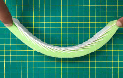
Biological structures have inspired synthetic materials with unparalleled performances such as ultra-lightweight design [1, 2, 3, 4], tunable elasticity [5, 6, 7, 8, 9], and negative poisson’s ratio [10, 11, 12, 13, 14]. Among biological structures, scales had appeared in the earliest stages of evolution of complex multicellular life [15] and continued their existence in spite of millions of years of evolutionary pressures. This has made scales a naturally high performance material with hybrid and multiscale response to various loads [16, 17, 18, 19, 20, 21, 22, 23]. For instance, scale covered organisms have inspired dermal armors fabricated using a soft substrate with plate-like ceramics embedded on the top layer [24]. This design showed that overlapping of scales provides flexibility, damage tolerance, and more importantly resistance to puncture. Similarly, armadillo scales have also been used as a source of inspiration for designing flexible armor fabricated using hexagonal glass plates placed on an elastomer substrate [25]. This type of synthetic armors also yielded a good resistance to puncture as well as flexibility. In addition, the development of flexible armor has also been implemented on fabrics [24, 26]. However, in addition to material response of the scales themselves, the scales serve as topological modifications to the underlying substrate. This ‘structural’ as opposed to the purely material aspect of scales reveals an entirely different regime of response encompassing interesting nonlinear behavior. In this case, typically scales are attached to a low dimensional flexible substrate such as a beam or a plate. In such cases, in contrast to armor like ‘local’ loading, scale arrangement influences global deformation behavior such as bending as the biomimetic scale beam shown in Fig. 1. For such scaly substrates, mechanical behavior depends critically on the kinematics of scale sliding.
In this context, particularly, scaly structures subjected to a pure bending moment have been intensively investigated due to their practical and theoretical importance in isolating kinematics and developing moment curvature relationships. For instance, in one of the earliest studies, the mechanism of deformation of a fish scale structure (with the assumption of deformable scales) was investigated where the authors demonstrated the strain-stiffening response in the structure [27]. Further work on deformable scales followed investigated stretch and buckling response of teleost fish structures [19]. To address the mechanics of two-dimensional scaly composite shells, a computational approach was proposed [28] to establish the relationship between structure and the mechanical response. The authors studied the structure under both bending and twisting types of loading. These studies clearly showed that stiffer scales at a low angle are desirable for maximum performance. Taking this route and simplifying such a high contrast system (stiff scales and soft substrates) with rigid scales helps isolate the role of scale kinematics on the mechanical nonlinearity. This simplified assumption leads to closed form analytical relationships connecting the kinematics to the mechanics. In this context, the kinematics and mechanics of a one-dimensional scaly beam, assuming rigid scales, have been addressed [29]. In this work, the authors assumed frictionless self-contact between scales. Their results revealed the existence of a three different regimes of mechanical response - linear, non-linear, and locking phase. The effect of friction in sliding kinematics of scales has then been further studied in [30]. The study revealed that friction does not alter the overall nature of behavior although it advanced the locking envelopes further. Further follow up studies which outlined the envelopes of validitity of the analytical models for rigid scale system were also carried out using extensive finite element (FE) analysis [31]. Furthermore, composite architecture with scales only embedded on the top layer of a soft substrate (imitating elasmoid fish scales) have been presented to account for the deformation mechanism due to compressive loading [32, 33]. In their work, the authors found that volume fraction of the embedded plate like scales has a prime role in changing the stiffness of an elastomer structure.
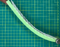
These prior investigations underscore the growing importance of using scales as topological additives on substrates. In order to fully develop the structure-property-architecture paradigm for this class of hybrid materials, models are of critical importance. This is because they do not only reveal and quantify the mechanism of nonlinear behavior but also indispensable for design and optimization of the architecture. Therefore, it is imperative that models accurately reflect salient aspects of the system. Thus far, all models have relied on the assumption of preserving periodicity throughout scales engagement. This assumption allows the isolation of a fundamental representative volume element (RVE), after which periodic boundary conditions are applied and a global derivative is affected to obtain the mechanical behavior [19, 27, 29, 30]. However, in any realistic structural application such post-engagement periodicity is seldom observed either at a global or local level beyond the simplest of the loading cases such as pure bending (see Fig. 1). Periodicity of engagement can be broken by simply applying different boundary and loading conditions. For instance, a cantilevered beam would not exhibit periodicity associated with pure bending. This is approximately shown in the contrasting geometries post engagement between Fig. 1 and 1. In fact, the density of scales needed to maintain even local periodicity for such cases is considerable and typically not observed in real systems which have discrete scales distribution. More importantly, an enormously dense scale system begins to mask the tunable nonlinearity specific to scale sliding due to the material constriction effect between the scales [29, 32]. Last but not the least, even for global periodicity, the number of scales in real structures are often not sufficient to justify a continuous distribution.
In spite of these known limitations, existing models still rely on periodic frameworks which cannot be directly applied or even extended to the non-periodic cases such as the case of a cantilever beam illustrated in Fig. 1. Therefore, it is imperative that investigation be based on more accurate models which could address the lack of periodicity and discrete nature of the scales. This work presents a more general theory of stiff scale covered elastic substrate to establish the kinematics and mechanics of a one-dimensional scaly beam using scale-by-scale interaction approach obviating the need for global or local periodicity. The theory is first applied to structures that undergo a uniform bending which are compared with results in literature [29]. The model is then validated using FE-based numerical studies to show the accuracy of our theory. Kinematics and mechanics of non-uniform bending structures will also be presented for the cases of simply supported and cantilever beams. The analytical results show a perfect match with FE results which prove that no other mechanical assumptions are needed to explain previous discrepancies.
2 Materials and Methods
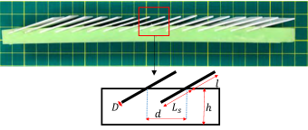
Geometry: The geometry of the system in the reference configuration is illustrated in Fig. 2. A periodic arrangement in the reference configuration is apparent. The underlying substrate is assumed to be a uniform beam of length . The length of the scale is assumed to be where is the exposed part of the scale and is the embedded part. The thickness of the scale is considered to be and the beam thickness is . It is further assumed that and , an assumption commonly made indicating scales thin are confined to the top of the substrate. We denote the ratio of scale length to separation as where is the distance between the scales. The scales start with an initial scale angle measured with respect to the beam centerline and rotates to an angle as the engagement proceeds.
.
Materials: A typical scaly biomimetic system features scales which are much stiffer than the underlying substrate. This study targets a system which could be comprised of a silicone based substrate of modulus MPa and poisson’s ratio and PLA plastic for scales with GPa. Clearly the moduli are widely divergent for these materials which allows for treating the scales as rigid as long as locking conditions are not realized [19, 31]. The strains are assumed to remain small and the beam can be approximated by the Euler-Bernoulli assumptions. A further un-stretchable constraint on the beam is imposed.
Kinematics: The periodicity after contact is a typically strong constraint and will be readily violated via boundary and loading conditions for a practical system. An example of this is the case of non-uniform bending such as cantilever or distributed loading. Local periodicity, however, could be maintained for very high density of scales but that would transition this system to a more composite and coating type systems dictated by material constrictions [32].
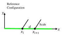
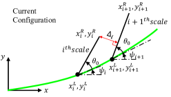
In order to address the breakdown of periodicity, a scale-by-scale discrete approach is introduced in this work. It is assumed that in the reference configuration, the position of the scale on the substrate is given by . A general material point on the substrate in the reference flat state is denoted by . This is shown in Fig. 3. The current configuration of the scale is quantified by the coordinates which are the left and right ends of the scale as shown in Fig. 3. In the case of pure bending, the typical measure of deformation is the curvature. However, for more general loading case an alternative way to devise deformation is presented in this paper using a shape function and its normalized amplitude which determines the extent of load. Therefore, in the current configuration, the material point now occupies a vertical position . In practice, is a unit less constant which depends on the load, beam geometry and substrate material. In pure bending, moment causes a substrate to deform into an arc. In small deflection, this arc will follow the form with the instantaneous curvature where is the length of the beam, is the bending moment, and is the flexural rigidity of the beam [34]. We non-dimensionalize the curvature with the beam thickness to get . On the other hand, the deflection of a simply supported beam of flexural rigidity and uniform loading has the form . In this case, . Finally a cantilever beam with point load at the tip deforms according to the function which makes [34].
With the assumption of unstretchability, a scale level geometry, shown in Fig. 3, emerges before engagement commences. From this geometry, we can write for any scale, before engagement:
| (1) | ||||
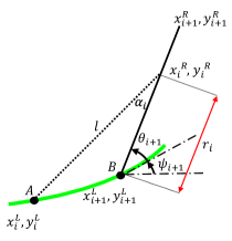
Where is the initial inclination angle of the scale and is the inclination angle of the beam at the base of the scale. This geometry will undergo further change as engagement proceeds. The scales engagement can be tracked using the distance parameter of the right extremity of the scale to the subsequent scale as shown in Fig. 3. This distance parameter can be written as [35]:
| (2) |
Where is the total number of scales. As becomes zero, engagement condition is met.
To illustrate the effect of geometry change after engagement, two sequential scales and at a general point of engagement is taken. This is shown in Fig. 4. At this point, scale is engaged with scale . After engagement, the geometry is constrained. The kinematics is governed by Eq. (1) with replaced with . Moreover, and are both unknown, which makes the geometry statically indeterminate. To resolve this impasse, an additional constraining condition utilizing the normal reaction moment balance between scales after engagement would be required. The scale rotation is modeled (similar to previous work [27, 29]) as a linear torsional spring which rotates about a fixed point. The spring constant is known to follow the analytical expression where is the modulus of elasticity of the substrate and , are constants with values , respectively [29]. However, using a new set of finite element (FE) simulations, was found to a more accurate value of 0.86 to specifically account for small initial inclination angles . In the case that scale is itself not engaged to , there are four unknowns which are , , , and . In order to obtain these unknowns, four constraining conditions would be required. These conditions are: the fixed length of the scale due to rigidity, the vanishing distance parameter due to contact, and the moment balance at the base of the and scale using the free body diagram illustrated in Fig. 4. Thus, the following equations emerge:
| (3) |
| (4) |
| (5) |
The constraining condition using the balance of the moment at the base of the scales is slightly more involved. For the case of engagement of only two scales, balancing the moment about points and , Fig. 4 yields
| (6) |
Where and with . The fourth equation is now
| (7) |
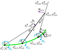
The four highly nonlinear Eqs. (3) through (5) and (7) must be solved numerically to obtain , , , and . Now extending this to a more general case of scales being engaged, the total number of unknowns would be: scale angles, , , coordinates of the right end of the scales , . Note that the coordinate requirements is reduced by one because the last scale undergoes no further engagements. This leads to a total of unknowns. The total number of equations include the equations which correspond to constraint on the length of the scales and which are based on the geometry of engagement of each scales excluding the last one. This yields a total of equations. Finally, an additional equation is generated through the moment balance at the base at the last (far right) scale. Thus we now have a system of unknowns and as many equations. Thus, balancing the moment about points and , Fig. 4, yields the following equation which can be utilized for finding the normal force between any two consecutive scales (except the case when or , for which Eq. (6) must be used):
| (8) |
Following the general procedure mentioned above, we can calculate the positions of all scales using a numerical solver such as available in commercial code MATLAB to maintain equilibrium at every step of deformation of the underlying substrate. Note that the angle of the right most scale will progressively decrease after engagement until it reaches an approximately zero angle. Accordingly, becomes known and the unknowns are only , , and . The structure now becomes statically determinate. Eqs. (3) through (5) can then be simplified to uniquely determine the position of the scale. After simplification, Eqs. (3) through (5) yield the following quadratic equation:
| (9) |
Equation. (9) has only one unknown and gives the right coordinate of the scale. From this equation, one can obtain as
| (10) |
and finally is calculated via Eq. (3). Note that Eqs. (3), (9), and (10) are only utilized for finding the equilibrium configuration of the scales once the far right scale has reached an approximately zero inclination angle.
Mechanics: To better understand the mechanics of a scaly structure, one can envisage that the bending mode is a combination of substrate bending and scales rotation. In other words, the structure stores energy during bending mode via the deflection of the beam and rotation of scales that is modeled as a linear torsional spring as described above [27, 29]. Thereafter, the mechanics of these structures is approached by employing the principle of minimization the total potential energy. We can write the total potential energy as . Here is the strain energy of the underlying beam, is the strain energy due to the rotation of scales, and is the work done by the applied load and is the Heaviside step function to track engagement. Since the deflection of the beam follows the form , the energetic principle is equivalent to finding that minimizes the potential energy through setting its first derivative to zero. This leads to the following variational energetic equation . In general, the deflection will be characterized by the following two steps. First, we adopt for the case of a virgin beam under appropriate loading conditions [34]. Once is acquired, the second step becomes finding an equivalent load that balances the increase in the energy due to scales interaction.
For the case of uniform bending, the work done by an applied moment is while the total energy stored in the system + The moment-curvature relationship can be then expressed as:
| (11) |
Here is numerically evaluated for all the rotation angles of scales and their corresponding curvature. This relationship is equivalent to the one derived in earlier studies [27, 29].
Non-uniform bending is illustrated through the examples of simply supported and cantilevered beams. For the case of a simply supported beam subject to a uniform distributed load , the work done can be written as The amplitude is and therefore the deflection of the midpoint of the virgin beam can be expressed as [34]. After engagement, the midpoint deflection will have the same formula. However, will be replaced with which is an equivalent load that provides the same midpoint deflection of a virgin beam including the effect of scales interaction. The equivalent load can be written as:
| (12) |
For simplicity, the midpoint deflection after the engagement of scales is written as .
Similarly, the work done in a cantilever beam due to a point load applied at the tip is . Therefore, the tip deflection is while [34]. The interaction of scales will make increase in order to obtain an equivalent deflection in the case of having un-scaly substrate. This load is expressed in Eq. (13), and it is the alternative to to find the tip deflection after the interaction of scales begins.
| (13) |
It is worth noting that the concept presented here can be applied to scaly structures with general types of loading and boundary conditions. Furthermore, to verify the kinematics and mechanics results of the three examples illustrated in this paper, finite element (FE) simulations using a commercially available code ABAQUS (Dassault systemes) were carried out. Several constraints were imposed on the models including rigid scales, surface-to-surface frictionless contact, and proper boundary conditions based on each example. Sufficient mesh density was used to ensure convergence in the results obtained.
3 Results and Discussion
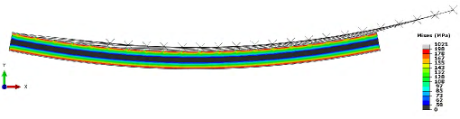
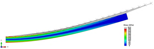
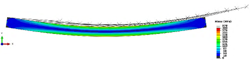
The regime where periodicity of scales engagement is preserved is first studied to compare with previous analysis. This is only observed when a scaly beam is uniformly bent, which is the case of applying a pure bending moment, and can be clearly seen in the von-Mises stress plots in the FE results shown in Fig. 5. The figure illustrates a uniform bending of a scaly beam consisting of scales in which the instant of engagement occurs at the same angle of curvature . However, beyond this limited case of uniform bending, it is clear that periodic engagement of scales in no longer valid as illustrated by the non-uniformity of the von-Mises stress contours. This is the case for non-uniform bending of the underlying substrate such as a cantilevered scaly beam, Fig. 5, and the case of uniform loading on a simply supported scaly beam, Fig. 5.
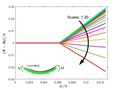
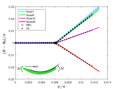
The previously developed analytical formulation of the kinematics can be used to study the scale angles for uniform bending. Such calculations reveal the extent of periodic engagement of scales by tracking the motion of all the scales in the structure with a total of scales with overlap ratio . The results are illustrated in Fig. 6 in which the angular displacement of the scales is plotted versus the rotation of the underlying substrate . The plots indicate same angles for all scales (horizontal line) until engagement curvature is reached, after which scales begin to change angles due to scale sliding. However, an important distinction arises from previous studies even for this case. Here, the scales angles begin to differ from each other violating periodicity. The scales are numbered starting from the left side as shown in the inset. The scales on the left of the mid-point (scale number ) increase in angle as expected from previous periodic theory. However, scales on the right of this point begin to decrease in angle. The verification of these predictions are carried out with FE simulations of an identical system for a few select scales (in this case selected randomly as number ,,, and ) and depicted in Fig. 6. The figure also compares this model with periodicity assumption used in the literature. Clearly, the current model shows an excellent match with the FE simulations for the kinematics.
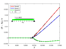
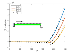
Non-periodic engagement of scales was also observed when the underlying substrate undergoes a non-constant curvature deformation. This makes periodicity impossible from the outset requiring using the presented analytical formulation. First, a simply supported beam subject to a uniform loading is studied. In this case, since quantifies the amplitude of the deflection of the beam and serves as proxy to curvature of previous plots. The results shown in Fig. 6 illustrates scale rotation angles with for select scales ,, and for brevity. The developed model once again gives excellent match with FE results. Note that the scales angles variation with deformation is not necessarily linear. Even more interestingly, a symmetry in the loading and boundary conditions did not lead to any symmetrical behavior in the scales kinematics. Clearly, the scale ‘handedness’, i.e. inclination of the scale played a crucial role in this symmetry breaking. Furthermore, scales engagement begins in the positions that possess higher curvature as the substrate continuously deforms. In the simply supported scaly beam, scales start engaging from the middle and then continue outwards from the center of the beam toward the edges. Additionally, the results show that the angle of scales placed near the right edge of the beam reduces until it touches the subsequent scale and thereafter starts increasing.
The other example presented to study scales angles of non-uniform bending is the deformation of a scaly cantilever type beam with a point load applied at the tip. The scales angles are plotted versus , and the results are depicted in Fig. 6. The figure clearly shows the non-periodicity of scales engagement. The asymmetry in the structure provides an increase in the scales angles after the engagement with a subsequent scale. It is noticeable that a cantilever scaly beam requires a small in order for scales to engage early unlike the case of a simply supported scaly beam. Higher will require much higher deformation to engage making the substrate stretch, which is neglected in the developed model. This seems to be the reason for the slight deviation in the results when comparing with FE. This could be an important factor for higher angle scales, although they are not typically considered to be as useful due to late engagement.
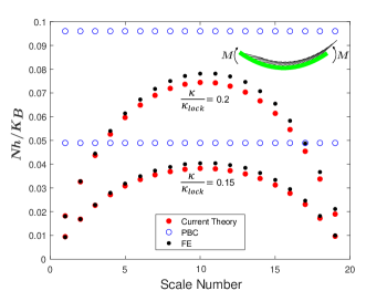
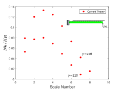
These results also forces a re-discussion on the limits of nonlinearity i.e. locking behavior (bending rigidity sharply increases due to transition from substrate to stiff scale bending) at which the sliding of the scales would eventually stop [27, 29]. For periodic engagement of rigid scales, a relationship that relates the locking angle of the scale to the substrate unit cell rotation was derived earlier [29]. This formula was derived based on studying the kinematics of a single RVE due to imposition of periodicity. The periodicity of the geometry makes any further motion geometrically impossible. The normal force (see Fig. 4 ) at this point is singular and same for all scales. However, in practical cases this point is never reached due to scale deformation or frictional effects even for minor coefficients of frictions [30]. In the current problem, the lack of periodicity precludes a kinematic lock. However, considering the critical importance of the normal reaction force, locking could be reformulated on the basis of normal reaction force. The normal force can be determined employing Eqs. (6) and (8) and plotted for all embedded scales in Figs. 7 through 7. Normal force will not be constant due to lack of periodicity. In fact, calculations in this paper reveals that the normal force which has been previously assumed to be the same for all scales when a scaly structure undergoes a uniform bending is not always true. The normal force in the results is normalized by the product of height of the beam and the spring constant . For the case of uniform bending, the theory developed above revealed that the non-dimensional normal force follows a parabolic shape, which indicates that the structure begins locking from the middle of the beam. Fig. 7, compares the normalized reaction forces utilizing the developed theory (Eqs. (6) and (8)) and the previous work with FE for the cases of 0.15 and 0.2 for pure bending. The was calculated following the formula . The figure also compares the constant normal reaction arising from the periodicity assumption at any given curvature. However, in reality this is not the case even for pure bending with maximum normal force in the middle which then decreases near the edges as shown in FE simulations, Fig. 7. This phenomenon is accurately predicted by the currently developed theory. The periodic theory also over predicts the normal reaction, which is also corrected in this work. However, for periodic contact, an ideal case for locking is a kinematic limit although it is likely that the spike in normal reaction in the middle of the mid prevents locking far earlier than kinematic prediction via deformation or friction (which would no longer remain negligible).
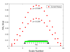
The theory also demonstrates that locking in symmetric scaly structures begins at the middle of the structure, and that is true even for the case of non-uniform bending of a simply supported beam subject to a uniform loading as depicted in Fig. 7. The figure illustrates the normalized reaction force between the scales for the two cases of and . On the contrary, the current results show that non-symmetric scaly beams will start locking near the edge that is exposed to the highest curvature. The results of tracking the force between scales in the cantilever scaly beam is shown in Fig. 7 for two cases of and . Finally, the presented theory demonstrated that locking would not take place globally in the structure, but in a more gentle progressive fashion.
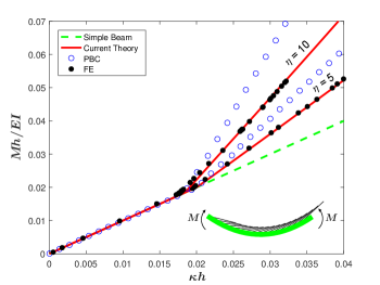
Turning now to mechanics to calculate load-displacement like characteristic, the developed model results in an excellent match between our results and those of FE simulations for all these cases. In the next examples, the results of the mechanical behavior of scaly beams have been normalized by the height of the beam. Figure. 8 depicts the non-dimensionalized moment-curvature relationship and illustrates how the overlap ratio plays a crucial role in stiffening the structure. The results are plots of the moment curvature for two cases of and . Our current theory exhibits an excellent match with the computational models, correcting previously reported deviations completely. This shows that simply allowing for non-periodicity is sufficient to capture most of the small deformation nonlinear mechanics of these substrates.
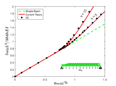
Additionally, the normalized mid-deflection of a simply supported scaly structure was plotted versus the solution obtained from the linear theory of the deflection of beams [34], and the results are shown in Fig. 8. Again, an addition in the stiffness of the underlying substrate requires higher , which can be increased by either increasing or decreasing . Note that lowering between scales may delay the engagement of scales unlike increasing , a direct conclusion from the vanishing distance parameter. The figure also exhibits a good match with the results obtained from FE.
For the cantilever beam, not much difference was found from the virgin beam for in contrast to the simply supported beam. This is because the curvature was not large enough to engage sufficient number of scales. Therefore, for cantilever simulation was utilized to effect an appreciable stiffness gain, Fig. 8. It is worth noting that even for the case of this higher , not all embedded scales has been engaged due to the low curvature near the tip of the cantilever scaly beam. The results shown in Fig. 8 show an excellent match between our theoretical model and computational results.
4 Conclusions
This paper presents an accurate and validated model for biomimetic scale based system relaxing the previous periodicity assumptions which would not be physical for a realistic system. This is a significant step towards developing the structure-property-architecture framework for topologically leveraged solids such as these opening way to better integration with additive manufacturing and possible topology optimization. The model introduces a new and more accurate way to predict the mechanical properties of the scale covered substrates. The analytical predictions for three test cases have been derived and thoroughly validated with finite element calculations. It was found that non-periodic post engagement behavior cannot be neglected as the errors could be significant. In the same vein, incorporating periodicity eliminated most of the discrepancies of the previous models completely thereby showing no further source of inaccuracies in the previous models. Using non-periodic general theory allows us to interpret locking more accurately since the original formulation depends on a simultaneous, locked position. It was found that locking in symmetric scaly structures begins at the middle of the structure and continues outward towards the edges. On the other hand, for the case of non-symmetric scaly beams, locking starts near the edge that is exposed to the highest curvature. Symmetric structures require less of an overlapping ratio than non-symmetric structures in order to gain a noticeable stiffness. This is important for a number of applications such as substrate design, soft robotic gripper, deployable structures etc. which would exhibit complex non-periodic and discrete type mechanics.
References
References
- [1] A. Hadadi, Understanding the effect of amide and amine groups on the structural and thermal properties of biomaterials as a function of ionic liquids, Ph.D. thesis, Rutgers University-Camden Graduate School (2017).
- [2] H. Bai, F. Walsh, B. Gludovatz, B. Delattre, C. Huang, Y. Chen, A. P. Tomsia, R. O. Ritchie, Bioinspired hydroxyapatite/poly (methyl methacrylate) composite with a nacre-mimetic architecture by a bidirectional freezing method, Advanced Materials 28 (1) (2016) 50–56.
- [3] J. Xiong, R. Mines, R. Ghosh, A. Vaziri, L. Ma, A. Ohrndorf, H.-J. Christ, L. Wu, Advanced micro-lattice materials, Advanced Engineering Materials 17 (9) (2015) 1253–1264.
- [4] K. Kendall, Thin-film peeling-the elastic term, Journal of Physics D: Applied Physics 8 (13) (1975) 1449.
- [5] D. Aydin, I. Louban, N. Perschmann, J. Blümmel, T. Lohmüller, E. A. Cavalcanti-Adam, T. L. Haas, H. Walczak, H. Kessler, R. Fiammengo, et al., Polymeric substrates with tunable elasticity and nanoscopically controlled biomolecule presentation, Langmuir 26 (19) (2010) 15472–15480.
- [6] K. Bootsma, M. M. Fitzgerald, B. Free, E. Dimbath, J. Conjerti, G. Reese, D. Konkolewicz, J. A. Berberich, J. L. Sparks, 3d printing of an interpenetrating network hydrogel material with tunable viscoelastic properties, Journal of the mechanical behavior of biomedical materials 70 (2017) 84–94.
- [7] M. Haque, G. Kamita, T. Kurokawa, K. Tsujii, J. P. Gong, et al., Unidirectional alignment of lamellar bilayer in hydrogel: One-dimensional swelling, anisotropic modulus, and stress/strain tunable structural color, Advanced Materials 22 (45) (2010) 5110–5114.
- [8] M. Kolle, A. Lethbridge, M. Kreysing, J. J. Baumberg, J. Aizenberg, P. Vukusic, Bio-inspired band-gap tunable elastic optical multilayer fibers, Advanced materials 25 (15) (2013) 2239–2245.
- [9] A. R. Studart, Biological and bioinspired composites with spatially tunable heterogeneous architectures, Advanced Functional Materials 23 (36) (2013) 4423–4436.
- [10] R. H. Baughman, S. Stafström, C. Cui, S. O. Dantas, Materials with negative compressibilities in one or more dimensions, Science 279 (5356) (1998) 1522–1524.
- [11] A. Ikai, Introduction to basic mechanics, in: The World of Nano-Biomechanics (Second Edition), Elsevier, 2017, pp. 17–34.
- [12] R. Lakes, Foam structures with a negative poisson’s ratio, Science (1987) 1038–1040.
- [13] R. S. Lakes, Negative-poisson’s-ratio materials: Auxetic solids, Annual Review of Materials Research 47 (2017) 63–81.
- [14] S. Xu, A. Mitra, S. Migues, J. Mayfield, M. Shinall, B. Derek, D. Linley, S. Russell, Self-shifting neutral axis and negative poisson’s ratio in hierarchical structured natural composites: Bamboo, in: Mechanics of Biological Systems and Materials, Volume 6, Springer, 2017, pp. 67–73.
- [15] B. J. Bruet, J. Song, M. C. Boyce, C. Ortiz, Materials design principles of ancient fish armour, Nature materials 7 (9) (2008) 748.
- [16] W. Chen, H. Zhang, Y. Huang, W. Wang, A fish scale based hierarchical lamellar porous carbon material obtained using a natural template for high performance electrochemical capacitors, Journal of Materials Chemistry 20 (23) (2010) 4773–4775.
- [17] T. Ikoma, H. Kobayashi, J. Tanaka, D. Walsh, S. Mann, Microstructure, mechanical, and biomimetic properties of fish scales from pagrus major, Journal of structural biology 142 (3) (2003) 327–333.
- [18] C. C. Lin, R. Ritch, S. M. Lin, M.-H. Ni, Y.-C. Chang, Y. L. Lu, H. J. Lai, F.-H. Lin, A new fish scale-derived scaffold for corneal regeneration, Eur Cell Mater 19 (2010) 50–57.
- [19] F. J. Vernerey, F. Barthelat, Skin and scales of teleost fish: Simple structure but high performance and multiple functions, Journal of the Mechanics and Physics of Solids 68 (2014) 66–76.
- [20] U. G. Wegst, H. Bai, E. Saiz, A. P. Tomsia, R. O. Ritchie, Bioinspired structural materials, Nature materials 14 (1) (2015) 23.
- [21] D. Zhu, L. Szewciw, F. Vernerey, F. Barthelat, Puncture resistance of the scaled skin from striped bass: collective mechanisms and inspiration for new flexible armor designs, Journal of the mechanical behavior of biomedical materials 24 (2013) 30–40.
- [22] M. Nelms, W. Hodo, A. Rajendran, Bioinspired layered composite principles of biomineralized fish scale, in: Blast Mitigation Strategies in Marine Composite and Sandwich Structures, Springer, 2018, pp. 397–421.
- [23] L. Szewciw, D. Zhu, F. Barthelat, The nonlinear flexural response of a whole teleost fish: Contribution of scales and skin, Journal of the mechanical behavior of biomedical materials 76 (2017) 97–103.
- [24] R. Martini, F. Barthelat, Stretch-and-release fabrication, testing and optimization of a flexible ceramic armor inspired from fish scales, Bioinspiration & biomimetics 11 (6) (2016) 066001.
- [25] R. K. Chintapalli, M. Mirkhalaf, A. K. Dastjerdi, F. Barthelat, Fabrication, testing and modeling of a new flexible armor inspired from natural fish scales and osteoderms, Bioinspiration & biomimetics 9 (3) (2014) 036005.
- [26] A. Lin, Design of flexible puncture resistant gloves inspired by natural dermal armors, Ph.D. thesis, University of Washington (2017).
- [27] F. J. Vernerey, F. Barthelat, On the mechanics of fishscale structures, International Journal of Solids and Structures 47 (17) (2010) 2268–2275.
- [28] F. J. Vernerey, K. Musiket, F. Barthelat, Mechanics of fish skin: A computational approach for bio-inspired flexible composites, International Journal of Solids and Structures 51 (1) (2014) 274–283.
- [29] R. Ghosh, H. Ebrahimi, A. Vaziri, Contact kinematics of biomimetic scales, Applied Physics Letters 105 (23) (2014) 233701.
- [30] R. Ghosh, H. Ebrahimi, A. Vaziri, Frictional effects in biomimetic scales engagement, EPL (Europhysics Letters) 113 (3) (2016) 34003.
- [31] R. Ghosh, H. Ebrahimi, A. Vaziri, Non-ideal effects in bending response of soft substrates covered with biomimetic scales, Journal of the mechanical behavior of biomedical materials 72 (2017) 1–5.
- [32] A. Browning, C. Ortiz, M. C. Boyce, Mechanics of composite elasmoid fish scale assemblies and their bioinspired analogues, Journal of the mechanical behavior of biomedical materials 19 (2013) 75–86.
- [33] S. Rudykh, M. C. Boyce, Analysis of elasmoid fish imbricated layered scale-tissue systems and their bio-inspired analogues at finite strains and bending, The IMA Journal of Applied Mathematics 79 (5) (2014) 830–847.
- [34] R. G. Budynas, J. K. Nisbett, et al., Shigley’s mechanical engineering design, Vol. 8, McGraw-Hill New York, 2008.
- [35] G. Thomas, R. Finney, Calculus and analytic geometry, 1996.