In Vivo WBAN Communication: Design and Implementation
The emerging in vivo communication and networking system is a prospective component in advancing healthcare delivery and empowering the development of new applications and services. In vivo communications is based on networked cyber-physical systems of embedded devices to allow rapid, correct and cost-effective responses under various conditions. This chapter presents the existing research which investigates the state of art of the in vivo communication. It focuses on characterizing and modeling the in vivo wireless channel and contrasting it with the other familiar channels. MIMO in vivo is also of cencern in this chapter since it significantly enhances the performance gain and data rates. Furthermore, this chapter addresses in vivo nano-communication which is presented for medical applications to provide fast and accurate disease diagnosis and treatment. Such communication paradigm is capable of operating inside the human body in real time and will be of great benefit for medical monitoring and medical implant communications. Consequently, propagation at the Terahertz (THz) frequency must be well understood as it is considered the most promising band for electromagnetic nano-communication models.
Keywords- In vivo communication, MIMO in vivo, nano-communication, THz frequency, WBAN.
1 Introduction
Wireless Body Area Networks (WBANs) are a new generation of Wireless Sensor Networks (WSNs) dedicated for healthcare monitoring applications. The aim of these applications is to ensure continuous monitoring of the patients’ vital parameters, while giving them the freedom of moving thereby resulting in an enhanced quality of healthcare [1]. In fact, a WBAN is a network of wearable computing devices operating on, in, or around the body. It consists of a group of tiny nodes that are equipped with biomedical sensors, motion detectors, and wireless communication devices which incoporates techniques similar to those implemetated in wireless systems [2, 3, 4, 5, 6, 7, 8, 9, 10, 11, 12, 13, 14]. Actually, advanced healthcare delivery relies on both body surface and internal sensors since they reduce the invasiveness of a number of medical procedures[15]. Electrocardiogram (ECG), electroencephalography (EEG), body temperature, pulse oximetry (SpO2), and blood pressure are evolving as long-term monitoring sensors for emergency and risk patients [16].
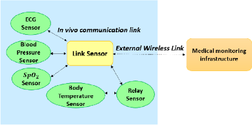
One attractive feature of the emerging Internet of Things is to consider in vivo networking for WBANs as an important application platform that facilitates continuous wirelessly-enabled healthcare [17]. Internal health monitoring [18], internal drug administration [19], and minimally invasive surgery [20] are examples of the pool of applications that require communication from in vivo sensors to body surface nodes. However, the study of in vivo wireless transmission, from inside the body to external transceivers is still at its early stages. Fig. 1 shows a modified network organization for interconnecting the biomedical sensors. The data is basically not directly transferred from the biomedical sensors to the hospital infrastructure. Indeed, sensors send their data via a suitable low-power and low-rate in vivo communication link to the central link sensor (located on the body like all other sensors). Any of the sensors may act as a relay between the desired and the central link sensor if a direct connection is limited. An external wireless link enables the data exchange between the central link sensor and the external hospital infrastructure [16].
Wireless in vivo communication creates a wirelessly-networked cyber-physical system of embedded devices. Such systems utilize real-time data to enable rapid, correct as well as cost-conscious responses for surgical, diagnostic, and emergency circumstances [15]. The crucial element that should be carefully regarded when referring to in vivo communications is modeling the in vivo wireless channel. The ability to understand the characteristics of the in vivo channel is fundamental to achieve optimum processing and design effective protocols that enable the arrangement of WBANs inside the human body [15].
This chapter surveys the existing research which investigates the state-of-art of the in vivo communication. It also focuses on characterizing and modeling the in vivo wireless channel and contrasting this channel with the other familiar ones. MIMO in vivo is also of interest since it significantly enhances the performance gain and data rates. Finally, this chapter introduces in vivo nano-communication as a novel communication paradigm. The rest of the chapter is organized as follows. In Section II, we present the state-of-art of in vivo communication. Conducted research on in vivo channel characterization is provided in Section III. The MIMO in vivo system is described in Section IV. In vivo nano-communication is addressed in Section V. Finally, we draw our conclusions and summarize the paper in Section VI.
2 State-of-art of In Vivo Communication
In vivo communication is a genuine signal transmission field which utilizes the human body as a transmission medium for electrical signals [21, 22, 23]. The body becomes a vital component of the transmission system. Electrical current induction into the human tissue is enabled through sophisticated transceivers while smart data transmission is provided by advanced encoding and compression. Fig. 2 shows the main components of an in vivo communication link.
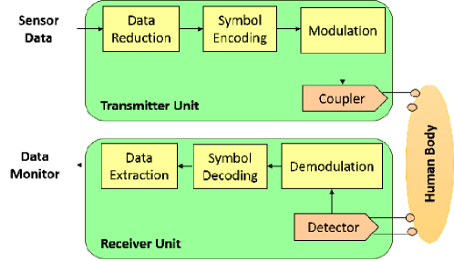
A transmitter unit permits sensor data to be compressed and encoded. It then conveys the data by a current-controlled coupler unit. The human body acts as the transmission channel. Electrical signals are coupled into the human tissue and distributed over multiple body regions. On the other hand, the receiver unit is composed of an analog detector unit that amplifies the induced signal and digital entities for data demodulation, decoding, and extraction [16].
Developing body transmission systems have shown the viability of transmitting electrical signals through the human body. Nonetheless, detailed characteristics of the human body are lacking so far. Not a lot is known about the impact of human tissue on electrical signal transmission. Actually, for advanced transceiver designs, the effects and limits of the tissue have to be cautiously taken into consideration [16][24]. The main requirements of an in vivo system include low power, low latency, less complexity, robustness to jamming, reliability, and size compactness [25]. In vivo communication is involved in a wide array of practical medical usages. For instance, in vivo sensors are utilized in health monitoring applications in order to keep track of glucose and blood pressure levels. In vivo actuators are also important for implanted insulin pumps as well as bladder controllers. Moreover, in vivo technology is involved in both medical nanorobotic device communication and in therapeutic nanoparticles employed in malignant tumor elimination processes. Such distinctive communication can add an effective contribution in the development of Prosthetics including artificial retina, cochlear implants and brain pacemakers for patients with Parkinsons disease.
2.1 Human Body Model
Research into in vivo communications primarily used the ANSYS HFSS [26] Human Body Model software to conduct the simulations. This software is a high-performance full-wave electromagnetic (EM) field simulator which enables the complete electromagnetic fields prediction and visualization. Hence, important parameters such as S-Parameters, resonant frequency, and radiation characteristics of antennas can be computed and plotted. The human body is modeled as an adult male body with more than 300 parts of muscles, bones and organs, having a geometric accuracy of 1 mm and realistic frequency dependent material parameters. The original body model only has the parameters from 10 Hz to 10 GHz. However, the maximum operating frequency is increased to 100 GHz by manually adding the values of the parameters to the datasets [27].
2.2 System Level Setup
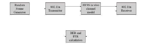
To evaluate the Bit Error Rate (BER) performance of the in vivo communication, an OFDM-based (IEEE 802.11n) wireless transceiver model operating at 2.4 GHz is setup. This model implies varying different Modulation and Coding Schemes (MCS) index values as well as bit rates in Agilent SystemVue for various in vivo channel setups in HFSS. The system block diagram is shown in Fig. 3 [28].
3 In Vivo Channel Modeling and Characterization
The in vivo channel is a novel paradigm in the field of wireless propagation; thus, it is very different when compared to other frequently analyzed wireless environments such as cellular, Wireless Local Area Network (WLAN), and deep space [2]. Fig. 4 illustrates the classic multi path channel and the in vivo multipath channel.
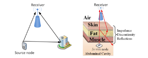
Basically, in an in vivo channel, the electromagnetic wave passes through various dissimilar media that have different electrical properties, as depicted in Fig. 4. This leads to the reduction in the wave propagation speed in some organs and the stimulation of significant time dispersion that differs with each organ and body tissue [28]. This is coupled with attenuation due absorption by the different layers result in the degradation of the quality of the transmitted signal in the in vivo channel.
The authors in [16] compare the characteristics of wireless technologies including the WLAN, Bluetooth, Zig-bee, and active Radio Frequency Identification (RFID) as shown in Table 1. Their aim is to seek a novel transmission technique for in vivo communication which focuses on transmission power below 1mW, data rates of 64 kbit/s, and the possibility for miniaturization to integrate the transceiver modules into band-aids and implantable pills.
| Technology | Frequency | Data Rate | Transmission Power | Size |
| WLAN | 2.4/5.1 GHz | 54 Mbit/s | 100 mW | PC card |
| Bluetooth | 2.4 GHz | 723.1 kbit/s | 1 mW | PCB module |
| Zigbee | 864 MHz | 20 kbit/s | 10 mW | PCB module |
| Active RFID | 134 kHz | 128 bit/s | <1 mW | pill |
| In vivo communication | <1 MHz | >64 kbit/s | <1 mW | band-aid/pill |
In addition, since the in vivo antennas are radiating into a complex lossy medium, the radiating near fields will strongly couple to the lossy environment. This signifies that the radiated power relies on both the radial and angular positions; hence, the near field effect has to be always taken into account when functioning in an in vivo environment [29]. The electric and magnetic fields behave differently in the radiating near field compared to the far field. Therefore, the wireless channel inside the body necessitates different link equations [30]. It must be noted as well that both the delay spread and multi-path scattering of a cellular network are not directly applicable to near-field channels inside the body. The reason behind this is the fact that the wavelength of the signal is much longer than the propagation environment in the near field [31].
The authors in [15] used an accurate human body to investigate the variation in signal loss at different radio frequencies as a function of position around the body. They noticed significant variations in the Received Signal Strength (RSS) which occur with changing positions of the external receive antenna at a fixed position from the internal antenna [15]. Nevertheless, their research did not take into account the basic characterization of the in vivo channel. In [25], the authors used an immersive visualization environment to characterize RF propagation from medical implants. Based on 3-D electromagnetic simulations, an empirical path loss (PL) model is developed in [32] to identify losses in homogeneous human tissues. In [33, 34, 35, 36], the authors carried out numerical and experimental investigations of biotelemetry radio channels and wave attenuation in human subjects with ingested wireless implants.
Modeling the in vivo wireless channel including building a phenomenological path loss model is one of the major research goals in this field. A profound understanding of the channel characteristics is required for defining the channel constraints and the subsequent systems’ constraints of a transceiver design [16].
3.1 Path Loss
Path loss in in vivo channels can be investigated using either a Hertzian dipole antenna or a monopole antenna. The authors in [31] carried out their study based on Hertzian dipole in which path loss is examined with minimal antenna effects. The length of the Hertzian dipole is so small resulting in little interaction with its surrounding environment. The path loss can be calculated as
| (1) |
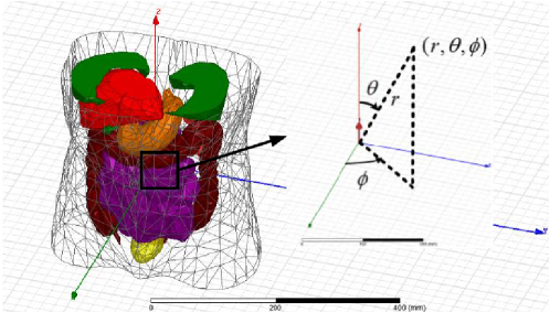
where represents the distance from the origin, i.e. the radius in spherical coordinates, is the azimuth angle and is the polar angle. is the the magnitude of the electric field at the measuring point and is the magnitude of electric field at the origin.
Due to the fact that the in vivo environment is an inhomogeneous medium, it is mandatory to measure the path loss in the spherical coordinate system [31]. The setup of this approach is depicted in Fig. 5 which includes the truncated human body, the Hertzian dipole, and the spherical coordinate system.
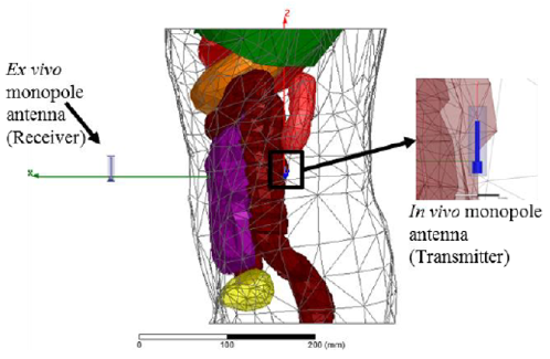
The authors in [15] carried out their study based on monopole antenna. Actually, monopoles are good choice of practical antennas since they are small in size, simple and omnidirectional. The path loss can be measured by scattering parameters (S parameters) that describe the input-output relationship between ports (or terminals) in an electrical system [15]. According to Fig. 6, if we set Port 1 on transmit antenna and Port 2 on receive antenna, then represents the power gain of Port 1 to Port 2, that is
| (2) |
where is the received power and is the transmitted power. Therefore, we calculate the path loss by the formula below
| (3) |
Based on the simulations presented in [31], it can be observed that there is a substantial difference in the behaviors of the path loss between the in vivo and free space environment. In fact, significant attenuation occurs inside the body resulting in an in vivo path loss that can be up to 45 dB greater than the free space path loss. Fluctuations in the out-of-body region is experienced by the in vivo path loss. On the other hand, free space path loss increases smoothly. The inhomogeneous medium results as well in angular dependent path loss [31].
3.2 Comparison of Ex Vivo and In Vivo Channels
The different characteristics between ex vivo and in vivo channels are summarized in [31] as shown in Table 2.
| Features | Ex vivo | In vivo | |||||
|---|---|---|---|---|---|---|---|
| Physical Wave Propagtion |
|
|
|||||
| Attenuation and Path Loss |
|
|
|||||
| Dispersion | Multipath delays-time dispersion |
|
|||||
| Directionality | Propagation essentially uniform |
|
|||||
| Near Field Communication | Deterministic near-field region around the antenna |
|
|||||
| Power Limitations | Average and Peak | Plus specific absorption rate (SAR) | |||||
| Shadowing | Follows a log normal distribution | To be determinted | |||||
| Multipath Fading | Flat fading and frequency selective fading | To be determinted | |||||
| Antenna Gains | Constant |
|
|||||
| Wavelength | The speed of light in free space divided by frequency |
|
4 MIMO In Vivo
Due to the lossy nature of the in vivo medium, attaining high data rates with reliable performance is considered a challenge [17]. The reason behind this is that the in vivo antenna performance may be affected by near-field coupling as mentioned earlier and the signals level will be limited by a specified Specific Absorption Rate (SAR) levels. The SAR is a measurement of how much power is absorbed per unit mass of conductive material, in our case, the human organs [37]. This measurement is limited by the Federal Communications Commission (FCC) which in turns limits the transmission power [37].
4.1 Capacity of MIMO In Vivo
The MIMO in vivo system capacity is the upper theoretical performance limit that can be achieved in practical systems, and can provide insight into how well the system can perform theoretically and give guidance on how to optimize the MIMO in vivo system [28]. The achievable transmission rates in the in vivo environment have been simulated using a model based on the IEEE 802.11n standard [38] because this OFDM-based standard supports up to 4 spatial streams (4x4 MIMO). Owing to the form factor constraint inside the human body, current studies are restricted to 2x2 MIMO.
The OFDM system can be modeled as:
| (4) |
where denote the received signal, transmitted signal, and white Gaussian noise with power density of respectively at OFDM subcarrier . The symbol is the total number of subcarriers configured in the system to carry data. The complex frequency channel response matrix at subcarrier is denoted by .
The SVD (Singular Value Decomposition) of is given as:
| (5) |
where , are unitary matrices, and is the nonnegative diagonal matrix whose diagonal elements are singular values of , , respectively.
The system capacity for subcarrier is [39]:
| (6) |
where is the total transmit signal power of the two transmitter antennas, is the configured system bandwidth in , and denotes expectation. In this chapter, only time-invariant Gaussian channels will be considered. Hence, the expectation in the capacity calculation will be ignored.
The total system capacity is calculated as:
| (7) |
where is the duration of each OFDM symbol, is the total number of subcarriers available in bandwidth , and is the guard interval.
4.2 Results of MIMO In Vivo
The authors in [28] analyzed the Bit Error Rate for a MIMO in vivo system. By comparing their results to a SISO in vivo, it was evident that significant performance gains can be achieved when using a MIMO in vivo. This setup allows maximum SAR levels to be met which results in the possibility of achieving target data rates up to 100 Mbps if the distance between the transmit (Tx) and receive (Rx) antennas is within 9.5 cm [37]. Fig. 7 below demonstrates the simulation setup that shows the locations of the MIMO antennas. Two Tx antennas are placed inside the abdomen while two Rx antennas are placed at different locations inside the body at the same planar height [28].
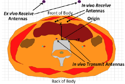
The antennas used in Fig. 7 are monopole antennas designed to operate at the 2.4 GHz ISM band in their respective medium which is either free space for the ex vivo antennas or the internal body for the in vivo antennas [28]. For the in vivo case, the monopole’s performance and radiation pattern varies with position and orientation inside the body; therefore, the performance of the in vivo antenna is strongly dependent on the antenna type [15][29].
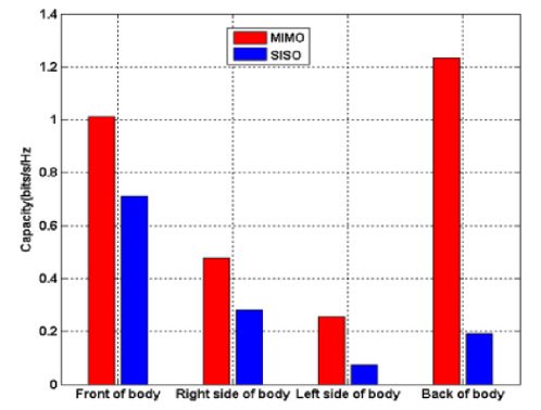
Further, in [17], it was proved that not only MIMO in vivo can achieve better performance in comparison to SISO systems but also considerably better system capacity can be observed when Rx antennas are placed at the side of the body. Fig. 8 compares the in vivo system capacity for front, right side, left side, and back of the body. In addition, it was noticed that in order to meet high data rate requirements of up to 100 Mbps with a distance between the Tx and Rx antennas greater than 12 cm for a 20 MHz channel, relay or other similar cooperative networked communications are necessary to be introduced into the WBAN network [17].
4.3 Applications of MIMO In Vivo
One prospective application for MIMO in vivo communications is the MARVEL (Miniature Anchored Remote Videoscope for Expedited Laparoscopy) [40]. MARVEL is a wireless research platform for advancing MIS (Minimally Invasive Surgery) that necessitates high bit rates ( - Mbps) for high-definition video transmission with low latency during surgery [41] .
5 In Vivo Nano-communication
Nanotechnology opens the door towards a new communication paradigm that introduces a variety of novel tools. This technology enables engineers to design and manufacture nanoscale electronic devices and systems with substantially new properties [42]. These devices cover radio frequencies in the Terahertz (THz) range and beyond, up to optical frequencies. The interconnections of nanodevices build up into nanonetworks enabling a plethora of potential applications in the biomedical, industrial, environmental and military fields.
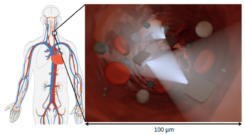
In vivo nanosensing systems [43], which can operate inside the human body in real time, have been recently proposed as a way to provide faster and more accurate disease diagnosis and treatment than traditional technologies based on in vitro medical devices. However, the sensing range of each nanosensor is limited to its close nano-environment; thus, many nanosensors are needed to cover significant regions or volumes. Moreover, an external device and user interaction are necessary to read the actual measurement. By means of such communication, nanosensors will be able to overcome their limitations and expand their applications [44]. Indeed, nanosensors will be able to transmit their information in a multi-hop fashion to a gateway or sink, react to instructions from a command center, or coordinate between them in case that a joint response to an event or remote command is needed. For instance, Fig. 9 shows several in vivo nanosensors that communicate as they travel through a blood vessel.
A number of challenges exist in the creation of in vivo nanosensor networks, which range from the development of nano-antennas for in vivo operation to the characterization of the intra-body channel environment from the nanosensor perspective [45].
In order to develop in vivo wireless nanosensor networks (iWNSNs), plasmonic nano-antennas for intra-body communication must be utilized [46]. In addition, a new view on intra-body channel modeling must be presented. In traditional channel models, the human body is modeled as a layered material with different permeabilities and permittivities. However, from the nanosensor perspective, and when operating at very high frequencies, the body is a collection of different elements (cells, organelles and proteins, among others), with different geometry and arrangement, as well as different electrical and optical properties. Further, coupling and interference effects among multiple nanosensors must be investigated and utilized at the basis of novel protocols for iWNSNs. The very high density of nanosensors in the envisioned applications results in non-negligible interference effects as well as electromagnetic coupling among nano-devices [45].
The future vision of in vivo networks entails the distribution of nano-machines that will patrol in the body, take measurements wherever necessary, and send collected data to the outside [47]. As a result, the development process and the operation of these devices invoke careful measures and high requirements. Moreover, it is important to understand in-body propagation at THz, since it is regarded as the most promising band for electromagnetic paradigm of nano-communication. Actually, the THz Band (0.1- 10 THz) is envisioned as a key technology that satisfies the increasing demand for higher speed wireless communication. THz communication alleviates the spectrum scarcity and capacity limitations of current wireless systems, and hence enables new applications both in classical networking domains as well as in novel nanoscale communication paradigms. Nevertheless, a number communication challenges exist when operating at the THz frequency such as propagation modeling, capacity analysis, modulation schemes, and other physical and link layer design metrics [47].
6 Conclusion
This chapter provided an overview of the in vivo communication and networking. The overview focuses on the state of art of the in vivo communication, the in vivo channel modeling and characterization, and the concept of MIMO in vivo. The chapter also addresses in vivo nano communication which is considered a novel communication paradigm that is going to revolutionize the concept of wireless body area networks. However, several challenges exist which open the door towards further research in this genuine field.
References
- [1] P. Honeine, F. Mourad, M. Kallas, H. Snoussi, H. Amoud, and C. Francis, “Wireless sensor networks in biomedical: Body area networks,” in Systems, Signal Processing and their Applications (WOSSPA), 2011 7th International Workshop on, May 2011, pp. 388–391.
- [2] D. Cypher, N. Chevrollier, N. Montavont, and N. Golmie, “Prevailing over wires in healthcare environments: benefits and challenges,” Communications Magazine, IEEE, vol. 44, no. 4, pp. 56–63, April 2006.
- [3] R. M. Shubair and H. Elayan, “In vivo wireless body communications: State-of-the-art and future directions,” in Antennas & Propagation Conference (LAPC), 2015 Loughborough. IEEE, 2015, pp. 1–5.
- [4] R. M. Shubair, “Robust adaptive beamforming using LMS algorithm with SMI initialization,” in 2005 IEEE Antennas and Propagation Society International Symposium, vol. 4A, Jul. 2005, pp. 2–5 vol. 4A.
- [5] R. M. Shubair and W. Jessmi, “Performance analysis of SMI adaptive beamforming arrays for smart antenna systems,” in 2005 IEEE Antennas and Propagation Society International Symposium, vol. 1B, 2005, pp. 311–314 vol. 1B.
- [6] M. S. Khan, A. D. Capobianco, S. M. Asif, D. E. Anagnostou, R. M. Shubair, and B. D. Braaten, “A Compact CSRR-Enabled UWB Diversity Antenna,” IEEE Antennas and Wireless Propagation Letters, vol. 16, pp. 808–812, 2017.
- [7] F. A. Belhoul, R. M. Shubair, and M. E. Ai-Mualla, “Modelling and performance analysis of DOA estimation in adaptive signal processing arrays,” in 10th IEEE International Conference on Electronics, Circuits and Systems, 2003. ICECS 2003. Proceedings of the 2003, vol. 1, Dec. 2003, pp. 340–343 Vol.1.
- [8] R. M. Shubair and A. Al-Merri, “Robust algorithms for direction finding and adaptive beamforming: performance and optimization,” in The 2004 47th Midwest Symposium on Circuits and Systems, 2004. MWSCAS ’04, vol. 2, Jul. 2004, pp. II–589–II–592 vol.2.
- [9] R. M. Shubair and Y. L. Chow, “A closed-form solution of vertical dipole antennas above a dielectric half-space,” IEEE Transactions on Antennas and Propagation, vol. 41, no. 12, pp. 1737–1741, Dec. 1993.
- [10] A. Omar and R. Shubair, “UWB coplanar waveguide-fed-coplanar strips spiral antenna,” in 2016 10th European Conference on Antennas and Propagation (EuCAP), Apr. 2016, pp. 1–2.
- [11] E. Al-Ardi, R. Shubair, and M. Al-Mualla, “Direction of arrival estimation in a multipath environment: An overview and a new contribution,” in ACES, vol. 21, 2006.
- [12] G. Nwalozie, V. Okorogu, S. Maduadichie, and A. Adenola, “A simple comparative evaluation of adaptive beam forming algorithms,” International Journal of Engineering and Innovative Technology (IJEIT), vol. 2, no. 7, 2013.
- [13] M. A. Al-Nuaimi, R. M. Shubair, and K. O. Al-Midfa, “Direction of arrival estimation in wireless mobile communications using minimum variance distortionless response,” in Second International Conference on Innovations in Information Technology (IIT’05), 2005, pp. 1–5.
- [14] M. Bakhar and D. P. Hunagund, “Eigen structure based direction of arrival estimation algorithms for smart antenna systems,” IJCSNS International Journal of Computer Science and Network Security, vol. 9, no. 11, pp. 96–100, 2009.
- [15] T. Ketterl, G. Arrobo, A. Sahin, T. Tillman, H. Arslan, and R. Gitlin, “In vivo wireless communication channels,” in Wireless and Microwave Technology Conference (WAMICON), 2012 IEEE 13th Annual, April 2012, pp. 1–3.
- [16] M. S. Wegmüller et al., “Intra-body communication for biomedical sensor networks,” Ph.D. dissertation, Diss., Eidgenössische Technische Hochschule ETH Zürich, Nr. 17323, 2007, 2007.
- [17] C. He, Y. Liu, T. Ketterl, G. Arrobo, and R. Gitlin, “Performance evaluation for mimo in vivo wban systems,” in RF and Wireless Technologies for Biomedical and Healthcare Applications (IMWS-Bio), 2014 IEEE MTT-S International Microwave Workshop Series on, Dec 2014, pp. 1–3.
- [18] E. Piel, A. Gonzalez-Sanchez, H.-G. Gross, and A. van Gemund, “Spectrum-based health monitoring for self-adaptive systems,” in Self-Adaptive and Self-Organizing Systems (SASO), 2011 Fifth IEEE International Conference on, Oct 2011, pp. 99–108.
- [19] E. Chow, B. Beier, Y. Ouyang, W. Chappell, and P. Irazoqui, “High frequency transcutaneous transmission using stents configured as a dipole radiator for cardiovascular implantable devices,” in Microwave Symposium Digest, 2009. MTT ’09. IEEE MTT-S International, June 2009, pp. 1317–1320.
- [20] Y. Sun, A. Anderson, C. Castro, B. Lin, R. Gitlin, S. Ross, and A. Rosemurgy, “Virtually transparent epidermal imagery for laparo-endoscopic single-site surgery,” in Engineering in Medicine and Biology Society, EMBC, 2011 Annual International Conference of the IEEE, Aug 2011, pp. 2107–2110.
- [21] T. G. Zimmerman, “Personal area networks (pan): near-field intra-body communication,” Master of Science in Media Arts and Sciences, Massachussetts Institute of Technology, 1995.
- [22] H. Elayan, R. M. Shubair, J. M. Jornet, and P. Johari, “Terahertz channel model and link budget analysis for intrabody nanoscale communication,” IEEE transactions on nanobioscience, vol. 16, no. 6, pp. 491–503, 2017.
- [23] H. Elayan, R. M. Shubair, and A. Kiourti, “Wireless sensors for medical applications: Current status and future challenges,” in Antennas and Propagation (EUCAP), 2017 11th European Conference on. IEEE, 2017, pp. 2478–2482.
- [24] D. Lindsey, E. McKee, M. Hull, and S. Howell, “A new technique for transmission of signals from implantable transducers,” Biomedical Engineering, IEEE Transactions on, vol. 45, no. 5, pp. 614–619, May 1998.
- [25] K. Sayrafian-Pou, W.-B. Yang, J. Hagedorn, J. Terrill, K. Yekeh Yazdandoost, and K. Hamaguchi, “Channel models for medical implant communication,” International Journal of Wireless Information Networks, vol. 17, no. 3-4, pp. 105–112, 2010. [Online]. Available: http://dx.doi.org/10.1007/s10776-010-0124-y
- [26] Ansoft, “ANSYS HFSS, 3D Full-wave Electromagnetic Field Simulation.” [Online]. Available: http://www.ansoft.com/products/hf/hfss/
- [27] C. Gabriel and S. Gabriel, “Compilation of the dielectric properties of body tissues at rf and microwave frequencies.” KING’S COLL LONDON (UNITED KINGDOM) DEPT OF, Tech. Rep., 1996.
- [28] C. He, Y. Liu, T. Ketterl, G. Arrobo, and R. Gitlin, “Mimo in vivo,” in Wireless and Microwave Technology Conference (WAMICON), 2014 IEEE 15th Annual, June 2014, pp. 1–4.
- [29] A. Skrivervik, “Implantable antennas: The challenge of efficiency,” in Antennas and Propagation (EuCAP), 2013 7th European Conference on, April 2013, pp. 3627–3631.
- [30] H. Schantz, “Near field phase behavior,” in Antennas and Propagation Society International Symposium, 2005 IEEE, vol. 3B, July 2005, pp. 134–137 vol. 3B.
- [31] Y. Liu, T. Ketterl, G. Arrobo, and R. Gitlin, “Modeling the wireless in vivo path loss,” in RF and Wireless Technologies for Biomedical and Healthcare Applications (IMWS-Bio), 2014 IEEE MTT-S International Microwave Workshop Series on, Dec 2014, pp. 1–3.
- [32] D. Kurup, W. Joseph, G. Vermeeren, and L. Martens, “In-body path loss model for homogeneous human tissues,” Electromagnetic Compatibility, IEEE Transactions on, vol. 54, no. 3, pp. 556–564, JUNE 2012.
- [33] A. Alomainy and Y. Hao, “Modeling and characterization of biotelemetric radio channel from ingested implants considering organ contents,” Antennas and Propagation, IEEE Transactions on, vol. 57, no. 4, pp. 999–1005, April 2009.
- [34] H. Elayan and R. M. Shubair, “On channel characterization in human body communication for medical monitoring systems,” in Antenna Technology and Applied Electromagnetics (ANTEM), 2016 17th International Symposium on. IEEE, 2016, pp. 1–2.
- [35] H. Elayan, R. M. Shubair, A. Alomainy, and K. Yang, “In-vivo terahertz em channel characterization for nano-communications in wbans,” in Antennas and Propagation (APSURSI), 2016 IEEE International Symposium on. IEEE, 2016, pp. 979–980.
- [36] H. Elayan, R. M. Shubair, and J. M. Jornet, “Bio-electromagnetic thz propagation modeling for in-vivo wireless nanosensor networks,” in Antennas and Propagation (EUCAP), 2017 11th European Conference on. IEEE, 2017, pp. 426–430.
- [37] T. Ketterl, G. Arrobo, and R. Gitlin, “Sar and ber evaluation using a simulation test bench for in vivo communication at 2.4 ghz,” in Wireless and Microwave Technology Conference (WAMICON), 2013 IEEE 14th Annual, April 2013, pp. 1–4.
- [38] “Ieee standard for information technology– local and metropolitan area networks– specific requirements– part 11: Wireless lan medium access control (mac)and physical layer (phy) specifications amendment 5: Enhancements for higher throughput,” IEEE Std 802.11n-2009 (Amendment to IEEE Std 802.11-2007 as amended by IEEE Std 802.11k-2008, IEEE Std 802.11r-2008, IEEE Std 802.11y-2008, and IEEE Std 802.11w-2009), pp. 1–565, Oct 2009.
- [39] D. Tse and P. Viswanath, Fundamentals of wireless communication. Cambridge university press, 2005.
- [40] C. Castro, S. Smith, A. Alqassis, T. Ketterl, Y. Sun, S. Ross, A. Rosemurgy, P. Savage, and R. Gitlin, “Marvel: A wireless miniature anchored robotic videoscope for expedited laparoscopy,” in Robotics and Automation (ICRA), 2012 IEEE International Conference on, May 2012, pp. 2926–2931.
- [41] C. Castro, A. Alqassis, S. Smith, T. Ketterl, Y. Sun, S. Ross, A. Rosemurgy, P. Savage, and R. Gitlin, “A wireless robot for networked laparoscopy,” Biomedical Engineering, IEEE Transactions on, vol. 60, no. 4, pp. 930–936, April 2013.
- [42] P. Russer and N. Fichtner, “Nanoelectronics in radio-frequency technology,” Microwave Magazine, IEEE, vol. 11, no. 3, pp. 119–135, May 2010.
- [43] M. A. Eckert and W. Zhao, “Opening windows on new biology and disease mechanisms: development of real-time in vivo sensors,” Interface focus, vol. 3, no. 3, p. 20130014, 2013.
- [44] I. F. Akyildiz and J. M. Jornet, “Electromagnetic wireless nanosensor networks,” Nano Communication Networks, vol. 1, no. 1, pp. 3–19, 2010.
- [45] J. M. Jornet, “Fundamentals of plasmonic communication for in vivo wireless nanosensor networks,” in 36th Annual International Conference on IEEE Engineering in Medicine and Biology Society (EMBC), Chicago, IL, USA, 2014.
- [46] Q.-H. Park, “Optical antennas and plasmonics,” Contemporary physics, vol. 50, no. 2, pp. 407–423, 2009.
- [47] I. F. Akyildiz, J. M. Jornet, and C. Han, “Terahertz band: Next frontier for wireless communications,” Physical Communication, vol. 12, pp. 16–32, 2014.