Thermomechanical response of thickly tamped targets and diamond anvil cells under pulsed hard x-ray irradiation
Abstract
In the laboratory study of extreme conditions of temperature and density, the exposure of matter to high intensity radiation sources has been of central importance. Here we interrogate the performance of multi-layered targets in experiments involving high intensity, hard x-ray irradiation, motivated by the advent of extremely high brightness hard x-ray sources, such as free electron lasers and 4-generation synchrotron facilities. Intense hard x-ray beams can deliver significant energy in targets having thick x-ray transparent layers (tampers) around samples of interest, for the study of novel states of matter and materials’ dynamics. Heated-state lifetimes in such targets can approach the microsecond level, regardless of radiation pulse duration, enabling the exploration of conditions of local thermal and thermodynamic equilibrium at extreme temperature in solid density matter. The thermal and mechanical response of such thick layered targets following x-ray heating, including hydrodynamic relaxation and heat flow on picosecond to millisecond timescales, is modeled using radiation hydrocode simulation, finite element analysis, and thermodynamic calculations. Assessing the potential for target survival over one or more exposures, and resistance to damage arising from heating and resulting mechanical stresses, this study doubles as an investigation into the performance of diamond-anvil high pressure cells under high x-ray fluences. Long used in conjunction with synchrotron x-ray radiation and high power optical lasers, the strong confinement afforded by such cells suggests novel applications at emerging high intensity x-ray facilities and new routes to studying thermodynamic equilibrium states of warm, very dense matter.
pacs:
62.50.-p, 07.35.+k 52.59.Px 52.50.Jm 41.60.CrI INTRODUCTION
Matter with an atomic density similar to that of the solid state, at temperatures of thousands to millions of degrees Kelvin and pressures exceeding millions of atmospheres, and undergoing rapid changes on microsecond to femtosecond timescales, is central to our understanding of planetary and stellar interiors, fusion energy technologies, and fundamental materials physics and chemistry. These warm dense matter states are not well described by the theoretical simplifications of traditional condensed matter physics or plasma physics. Laboratory experiments are thus critical for developing a physical understanding of this regime of temperature, density, pressure, and timescale. The creation and probing of warm dense matter in the laboratory often relies on central facilities capable of delivering high-brilliance irradiation, which can rapidly generate extreme temperatures in dense (i.e. solid or liquid) targets by ultrafast (fs-ps) ‘isochoric’ heating, or by the production of dynamic compression waves within the target facilitated by the expansion of heated matter on longer (ps-ns) timescalesNg et al. (2005); Sentoku et al. (2007); Fletcher et al. (2014). Ultrafast techniques have been widely employed to study the case of isochoric heating at timescales from femtosecond energy delivery to electrons, to picosecond heating of the lattice ions and hydrodynamic expansion into a vaporPatel et al. (2003); Gregori et al. (2005); Ivanov and Zhigilei (2003); Lévy et al. (2015); Sentoku et al. (2007).
A common strategy uses electromagnetic radiation, often in the optical or UV range, to deliver the intense energy burst. In such photonic experiments energy is delivered directly to electrons, which then transfer energy to the ions (lattice) as the system relaxes toward a state of local thermal equilibrium (LTE), a prerequisite for reaching local thermodynamic equilibrium conditions. The timescale of equilibration between the ions and electrons is typically on the order order of psWhite et al. (2014); Zastrau et al. (2014); Mostovych and Chan (1997); Ivanov and Zhigilei (2003). As electron-ion equilibration occurs roughly coincident with the expansion, melting, and vaporization processes naturally coupled to lattice heating, a loss of high-density conditions and sample confinement can occur before LTE is achieved, leading to study of nonequilibrium matter exclusively. The experimental timescale is also controlled by the size of targets, which in high power but low photonic-energy experiments is limited by short radiation absorption lengths, even in dielectrics. Such practical challenges of using radiation heating to study equilibrium warm dense matter in the laboratory often complicate the experimental study of equilibrium extreme systems common in nature and technology. Other methods of irradiative volumetric energy deposition providing access to similar states of matter have similar limitations, include intense protonPatel et al. (2003); Ping et al. (2015), heavy ionTahir et al. (2017), and electronWhite et al. (2014) beams. Dynamic compression, the driving of compression (i.e. shock or ramp) waves traveling at near sound velocities (1-10 m/ns) Ng et al. (2005); McWilliams et al. (2010); Fletcher et al. (2014); Kraus et al. (2017); Falk et al. (2018); Eggert et al. (2010), is a somewhat slower form of volumetric energy delivery, while diffusiveGoncharov et al. (2010, 2012); McWilliams et al. (2015); Konôpková et al. (2016) (as opposed to ballisticGregori et al. (2005); Ping et al. (2006); Sentoku et al. (2007)) heat conduction is even slower. While these latter approaches in principle provide better access to equilibrium states of warm dense matter, they are limited by restriction to adiabatic pathways (dynamic compression) and by the aforementioned challenges of confining very hot matter (diffusion).
One strategy to extend the lifetime of an irradiation-driven warm dense state is to provide a tamper material around samples through which energy may be deposited and which delay, prevent, or otherwise control expansionTahir et al. (2017); Mostovych and Chan (1997); Ping et al. (2015); Vailionis et al. (2011); Johnson et al. (2005); Bailey et al. (2003), such as by extending the time it takes pressure release waves and cracks to propagate through the heated target. This tamping approach can even confine the heated region entirely, enabling recovery of high density samples quenched from conditions that would normally lead to vaporization Vailionis et al. (2011). For optical radiation, tamping can be achieved by placing an absorptive (i.e. metal) layer between transparent (i.e. dielectric) tamper materialsMostovych and Chan (1997); Ping et al. (2015); Johnson et al. (2005), by tightly-focussing the beam within the tamper itselfVailionis et al. (2011), or other configurations such as utilizing energetic electron transport to deposit energy deeply in a targetSentoku et al. (2007). However, tamping using high-power optical laser irradiation is limited by the need to deliver sufficient energy through the tamper to the sample, and thus depends on the optical transmission of the material under high brightness radiation, often requiring thin tampers at all but the lowest irradiancesMostovych and Chan (1997) which limit the efficacy of this strategy. Targets of m level thicknesses with experimental lifetimes of ps, set by unconfined hydrodynamic expansion, remain common.
Intense x-rays also rapidly heat matterZastrau et al. (2008); Nagler et al. (2009); Vinko et al. (2012); Ping et al. (2015); Zastrau et al. (2014); Fletcher et al. (2014); Glenzer et al. (2016); Lévy et al. (2015); Saunders et al. (2018). This energy deposition may be introduced deliberately (e.g. to heat or otherwise excite electrons in a sample) or may be a side effect of probing samples with a high intensity x-ray beam. X-ray heating does not depend on damage thresholds of targeted materials, as in optical laser experiments, but instead depends nearly linearly on their x-ray absorption properties, which depend on atomic number Z. For deliberate heating strategies, the potentially longer absorption lengths enable more homogenous heating compared, e.g. to optical lasers or ion beamsNagler et al. (2009); Lévy et al. (2015); Saunders et al. (2018), and scaling up of targets to enable larger irradiated volumesLévy et al. (2015); Saunders et al. (2018). X-ray heating performed with large optical laserPing et al. (2015); Saunders et al. (2018), pulsed-powerBailey et al. (2003), and free electron laser (FEL) Zastrau et al. (2008); Glenzer et al. (2016); Nagler et al. (2009); Zastrau et al. (2014); Ping et al. (2015); Fletcher et al. (2014); Lévy et al. (2015) facilities have been demonstrated extensively at lower photon energies (hundreds of eV to several keV) which can still limit the potential thickness and materials of target components and hence experimental timescales.
Free electron lasers and other high-brightness x-ray sources operating in the hard x-ray regime above 10 keV (Table 1) allow for substantial scaling up of target dimensions and experimental timescales. At x-ray energies exceeding 10 keV, absorption lengths in even heavy-element solids exceed several m enabling large volume homogenous irradiationLévy et al. (2015); Saunders et al. (2018). Moreover, x-ray absorption lengths are at the mm level above 10 keV in common light element solids, allowing delivery of x-ray energy through thick low-Z tampers to high-Z samples. The possibility of massive tampers which remain cold and stable during the experiment, and which completely control the sample’s expansion, may thus be realized with such hard x-ray sources. For hard x-ray FELs, the high total pulse energy (1 mJ, or 1012 photons), fast timescale (10-100 fs), and high brightness (1018 W/cm2) is comparable to typical optical laser systems; similar total energies in somewhat longer pulses (100 ps) are possible at fourth-generation synchrotron radiation sources (Table 1). In addition to presenting challenges in adapting conventional x-ray probing studies to modern brilliant light sources, these capabilities presage a new generation of irradiative extreme temperature experiments. Radiatively heated samples in such experiments can, depending on target design, survive longer than those in lower energy experiments, enabling the achievement and exploration of more nearly thermal and thermodynamic equilibrium conditions, and study of processes normally out of range in ultrafast experiments such as diffusive heat conduction, bulk chemical reaction, equilibrium phase transformation, and phase separation and mixing.
| 4th Generation X-ray Sources | |||||
| Pulse | X-ray | Minimum | Pulse | ||
| Facility | Duration | Energy | Energy | Spot Size | Delay |
| [ps] | [mJ] | [keV] | [m] | ||
| Hard X-ray Free Electron Lasers | |||||
| LCLS-II-HELinac Coherent Light Source (2017); LCL (2015); Raubenheimer (2018) | 0.01-0.06 | 1-3 | 25 (12.8) | 3 | 8.3ms (1s) |
| European XFEL | 0.05 - 0.1 | .35 - 4 | 5 - 20 | 220ns | |
| SACLAYabashi, Tanaka, and Ishikawa (2015) | 0.01 | 0.5 | 4-15 | 1 | 17ms |
| Synchrotron Upgrades | |||||
| ESRF-EBSGarbarino (2017) | 100 | .04 | 10-70 | 0.15 | 176ns |
Many interesting and poorly understood phenomena at warm dense matter conditions are found at elevated densities, i.e. exceeding that of the solid state, including metallization of molecular insulatorsCelliers et al. (2018) and phase separation in warm dense mixtures Kraus et al. (2017); McWilliams et al. (2015); Schöttler and Redmer (2018). To access these conditions via irradiative heating requires that samples be initially pre-compressed to the needed density. The effects of increasing density on fundamental interactions in irradiatively heated matter including bondingMedvedev, Jeschke, and Ziaja (2013); Johnson et al. (2005) and electron-ion thermalizationZastrau et al. (2014); Nagler et al. (2009); White et al. (2014) also require investigation. The ability to employ confining tamper layers of substantial thickness in hard x-ray experiments (if of sufficiently low-Z composition) raises the possibility of using these layers as anvils to apply initial pressure to matter prior to x-ray probing or excitation. Such a design is commonly used in static high pressure devices, notably the diamond anvil cell (DAC), which employs thick (several mm) diamonds to isothermally compress thin samples to high pressure and density Mao and Mao (2007). Long-used at synchrotron facilities, and compatible with hard x-ray illumination as either a probe or pump, the DAC offers the possibility to study the properties and dynamics of high density, pressure and temperature material states on ultrafast timescales when coupled to brilliant x-ray sources. Many x-ray measurements developed for static high-pressure devices at traditional synchrotrons stand to be adapted for use at modern higher-brightness sources, such as characterization of dynamic pressure and temperature modulationJenei et al. (2019); Goncharov et al. (2010) with serial x-ray probing (Table 1). Static compression can also maintain sample confinement and high density during heating to the electron-volt (10,000 K) temperatures of warm dense matterMcWilliams et al. (2015), allowing near-isochoric experiments orders of magnitude beyond hydrodynamic timescales.
The purpose of this study is several-fold, and motivated by the increasing brightness of hard x-ray sources providing fast pulsed (nanosecond to femtosecond) hard x-rays (to tens of keV) at high power (1011-1012 photons per pulse). The main objective is to explore the thermal and mechanical evolution of pulse-irradiated targets involving particularly thick tampers, a configuration suggested by the ability of hard x-rays to pass unimpeded through low-Z tampers to a high-Z target layer confined within, to which energy is delivered. One application of interest is extending isochoric radiative heating studies by delaying or inhibiting altogether hydrodynamic expansion, so that matter can be observed at thermal, and plausibly thermodynamic, equilibrium while at extreme temperature and near-solid density. A related objective is to characterize the performance of diamond anvil high-pressure cells (DACs), long used to great effect in synchrotron x-ray science, at higher intensity pulsed x-ray sources where heating during the x-ray exposure could be an unavoidable byproduct of x-ray probing or used deliberately to heat pre-compressed matter to extreme temperature, as an alternative to optical laser heatingDewaele, Fiquet, and Gillet (1998); Mao and Mao (2007); Goncharov et al. (2010); McWilliams et al. (2015). The response of the anvil-cell type of tamped target to high brightness irradiation, and the designs it inspires for general tamped laser-matter interaction experiments, are discussed in Sec. IV.3. We also aim to characterize in general the heat dissipation in solid layered targets which may be of practical use as beamline opticsSinn (2007) and detectorsRoth et al. (2018) at x-ray facilities. The survival of these components often depends on their heat and stress dissipation capabilities and often utilize high strength, high thermal conductivity materials such as diamondSinn (2007); Roth et al. (2018).
II METHODOLOGY
Targets simulated here consist of a sample layer or layers (m thickness) between thick (mm thickness) tampers. The advantages of this configuration are: (1) exceptionally long confinement of samples at extreme conditions, so that the approach to, and properties of, thermodynamic equilibrium states of high density and temperature can be studied; (2) efficient control of sample temperature by using high thermal conductivity tampers, enhancing sample stability and promoting sample survival after irradiation; and (3) the ability to pre-compress samples with strong tampers, and resist thermomechanical stresses developing during the irradiation.
The thermomechanical response of these micron-to-millimeter scale x-ray heated layered targets evolves on a range of timescales. We consider a high-brightness monochromatic hard x-ray source, with a FEL-like beam diameter and pulse duration, delivering heat energy by x-ray absorption in 100 fs. Pressure waves generated by thermal expansion propagate on ps-ns timescales, adiabatically mediating pressure and temperature evolution in the differentially heated target; the timescaleGomez-Perez, Rodriguez, and McWilliams (2017) is set by the scale length of the heated volume divided by the sound speed , i.e. . Adiabatic conditions break down on ns-s timescales, with heat conduction cooling heated areas toward the initial temperature, at which the surrounding target remains; the timescaleGomez-Perez, Rodriguez, and McWilliams (2017) of this process is roughly the square of the heated volume size divided by the thermal diffusivity coefficient , or . On these lengthscales (micron to millimeter) and timescales (ps and longer) LTE can be assumed, and target conditions develop primarily as a result of conventional hydrodynamic processes and diffusive heat transport in locally equilibrated matter; near-isochoric conditions are assumed to be maintained throughout by stable tampers.
To study heat conduction, we use a two-dimensional finite element (FE) model including conduction along and lateral to the x-ray beam path, both important on the associated (s) timescales for tightly focussed radiation (Sec. II.1). To study the hydrodynamic processes, which can take the form of shock discontinuities, we separately employ one-dimensional radiation hydrodynamics models to study the mechanical and associated thermal evolution of the system for the first few ns (Sec. II.2); this approach is chosen because finite element models are not well suited to stress waves of larger magnitude, and because, if beam diameter is kept greater than the thickness of the relevant layers, the initial evolution of sample conditions is accurately treated as a one-dimensional process in the direction of the beam.
II.1 Finite Element Models
II.1.1 General approach
In order to describe the pulsed x-ray heating and cooling of a tamped sample configuration, we used a simulation software (comsol Multiphysics) based on finite element analysis to implement a two-dimensional, time-dependent heat transfer modelKonôpková et al. (2016); Goncharov et al. (2012); Gomez-Perez, Rodriguez, and McWilliams (2017); McWilliams et al. (2015), with semi-transparent materials exhibiting a bulk absorption of the x-ray radiation. We simulate the case of a single intense x-ray pulse of 100 fs duration, and later (Sec. IV.1) a train of such pulses, striking a sample initially at room temperature (300 K).
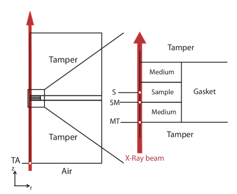
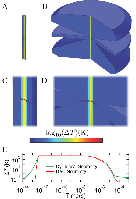
Assuming a multilayer target of layers perpendicular to the incident x-ray beam (Fig. 1), we exploit the symmetry around the beam, and consider a two-dimensional model by a rotational symmetry about an axis through the center of the beam path, with referring to the axial position and the radial position. The pulsed x-ray beam propagates in the direction, centered at . Including time , this model is three dimensional. We vary the geometries of the layers used in the system as needed to simulate different configurations. Thick, low-Z tampers (or anvils) of 2 mm thickness are placed on either side of a primary sample ‘foil’ layer of 5 m thickness. Additional interfacial layers (or medium), of several m thickness, are used between the tamper and foil in most simulations. The medium can play several roles in experiments, acting as: (1) a protective layer, preventing direct heating of the tamper and absorbing thermal stress when resisting hydrodynamic expansion; (2) as an insulating layer to extend the experimental duration by limiting cooling of the sample; and (3) as a hydrostatic pressure medium, in cases where the target is configured as a high pressure cell. The sample (and where used, medium) are contained laterally by a thick layer bridging the two tampers (or gasket, a component designed to reflect the configuration of anvil cells, which has little effect on the simulations). Typical dimensions are shown in Table 2. This geometry is also symmetric about a parallel plane through the middle of the sample layer; conditions achieved, however, are asymmetric about this plane. Constant volume conditions are assumed, which is appropriate if targets remain in the condensed state (i.e. below vaporization points) or where they are configured to resist thermal stresses and hydrodynamic expansion, e.g. using thick tamper layers or an anvil cell design having a fixed sample cavity volumeDewaele, Fiquet, and Gillet (1998). The effects of thermal expansion and stress waves are treated separately as these occur on significantly different timescales and require a self-consistent hydrodynamic approach due to the rapid nature of heating and consequent shock production (Sec. II.2).
| Fixed Dimensions, | |
|---|---|
| Finite Element Models | |
| Parameter | Value[m] |
| Model Domain Radius | 160 |
| Foil Radius | 40 |
| Medium Radius | 40 |
| Tamper Thickness () | 2000 |
| Foil Thickness () | 5 |
In order to describe the dynamical temperature evolution of targets, we used the finite-element solution of the time-dependent energy transfer equation. The volumetric heat source (the net energy generated per unit volume and time) representing the radiative energy absorbed within the target is given as
| (1) |
where is the temperature, is the time, is the thermal conductivity, is the density, and is the heat capacity at constant pressure. For constant physical properties, and considering the period after heating, Eq. 1 reduces to
| (2) |
where is the thermal diffusivity,
| (3) |
Radiative (photon) heat transfer is generally negligible compared to diffusive (phonon and electron) heat conduction at the presently examined temperatures and timescalesGomez-Perez, Rodriguez, and McWilliams (2017), and is not included.
The source term (typical units of W/m3) is given by volumetric heat generation when the incident x-ray beam passes through, and is absorbed within, the semi-transparent materials. Due to this absorption the beam intensity decays exponentially with depth (Lambert-Beer law). At the considered x-ray energies, the contribution of diffuse scattering to total attenuation is small and is neglected in our calculations. Coherent scattering (i.e. Bragg diffraction) could become important particularly where thick single crystals are used as tampers, affecting attenuation and radiation trajectory, though, as it can be avoided in practiceLoveday, McMahon, and Nelmes (1990), it is also ignored. The energy deposition in a given homogenous layer in a target can thus be written as
| (4) |
where is the absorption coefficient, constant in the layer, is the position of the layer surface the radiation is incident on, is the reflectivity of the leading surface or interface, and is the incident intensity on the surface (typical units of W/m2). For x-ray radiation, reflectivities of interfaces are exceedingly small, of order , and may be neglected. Thus the attenuation of x-rays as well as the energy deposition is accurately estimated by considering absorption only.
The absorption in the target is given by computing the sequential absorption in several such layers. At the downstream surface of a layer, boundary conditions establish that any light reaching that boundary will leave the domain and pass to the next layer and this is repeated until the beam reaches the downstream target surface and leaves the geometry. For example, in the center of the sample (and target), we have
| (5) |
where , , and refer to the sample, medium, and tamper values, respectively, is the incident intensity on the target assembly, refers to the thickness of particular layers, and refers to the center of the sample layer (and target assembly), hence only half of the sample’s thickness is included.
| Pulse Parameters, | |
|---|---|
| Finite Element Models | |
| Parameter | Value[units] |
| Arrival time () | 400[fs] |
| Pulse length () | 100[fs] |
| Pulse size () | 5[m] |
The model considers heating induced during a 100 fs duration x-ray pulse, and the conductive heat transfer following the rapidly imposed temperature distribution in the target. The heating pulse intensity is assumed to follow a Gaussian distribution in time and space, with incident intensity (Eq. 6) reaching a maximum, , at and as
| (6) |
where is a Gaussian radius parameter, such that the FWHM (full width at half maximum) diameter of the pulse is
| (7) |
and defines the temporal width of the pulse (FWHM) as
| (8) |
For the parameters of this simulation (Table 3) the spot size is then 12 m, and the pulselength 240 fs. The incident peak intensity can be related to the net energy of the single pulse (in J), the peak incident power (in W, and occurring at ), and the peak energy density per area (in J/m2, and occurring at ) as
| (9) | ||||
| (10) | ||||
| (11) |
The number of photons per pulse is
| (12) |
and is equivalent to for the peak energy per pulse (3.5 mJ) and x-ray energy (25 keV) simulated here. In our models we specify (Eq. 9), which when integrated over the pulse duration (Eqs II.1.1 and 6) leads to independent of the pulse duration, such that immediately after the pulse (and before significant heat transport occurs) depends only on total pulse energy and its spatial distribution, i.e. temperature achieved is independent of pulselength so long as the pulselength is shorter than heat conduction timescales. This implies any pulse duration less than the heat conduction timescales (roughly in the ns range or less) will achieve similar peak temperature and show identical cooling behavior.
The initial temperature of the entire system is assumed to be ambient (300 K). As a boundary condition, the external surface of the simulation cell shown in Fig. 1 was given by natural heat exchange with a surrounding atmosphere (air), with the external temperature fixed at 300 K, and heat loss from the surface determined as
| (13) |
where is the convective heat flux and is the convective heat transfer coefficient ( W/m2/K, for natural convection in air). This has no significant effect for the cooling timescale of these experiments; similar results could be expected in vacuum.
A free triangular mesh is employed, which is kept very fine at interfaces due to the need to stabilize the model during the initial phase of large temperature gradients at interfacial regions, at heating times to s; the heat transfer starts at approximately on s time scales, and temperature is stable before this if the simulation is configured properly. A coarser mesh is used away from the interfaces. The accurate modeling of interfaces on shorter timescales is validated analytically (Sec. III.1.8).
As the simulations seek to establish general trends for the effects of target composition, geometry, and beam parameters, a number of physical assumptions are made in our calculations. We assume a direct relationship between the amount of x-ray energy deposited in the target at a given location and the amount of heating at this location. Further, the models assume that thermal equilibrium (i.e. between electrons, which initially absorb energy, and ions, which heat more gradually on the ps timescale of electron-ion equilibration) occurs instantly. Thus our simulations should be accurate at timescales of 10-12 s and longer, i.e. sufficiently greater than electron-ion equilibration times, while only approximating the initial (fs) heating process. Implicitly, we also assume localization of hot electrons during the equilibration period, i.e. that any hot electrons produced ultimately equilibrate with nearby ions. This is a reasonable approximation since the typical mean free path of ballistic hot (eV) electrons in condensed matter tends to be of order m Ping et al. (2015); Nagler et al. (2009); Medvedev, Jeschke, and Ziaja (2013), which is much less than the sample dimensions and heating beam diameter (1-103 m), consistent with a diffusive heat transfer model being sufficiently accurate on these time and lengthscales. While not included here, hydrodynamic (Sec. II.2) and radiative processes, longer-distance hot electron transport (e.g. Refs. Falk et al. (2018); Sentoku et al. (2007)), and nonlinear absorption due to high x-ray fluence or short timescale e.g. resulting from mass ejection of core electronsVinko et al. (2012) and saturation of absorptionNagler et al. (2009), can modify initial temperature distributions, but cooling behavior will be similar. With a propagation time across the entire target of 10-11 s, it suffices for our purposes to assume the x-ray beam is incident in all points of the target simultaneously.
II.1.2 Materials parameters
A suite of materials with varying properties are included in the models to examine the possible range of heating and cooling behavior under x-ray irradiation. As the degree of x-ray absorption in a substance is roughly given as
| (14) |
where atomic number and mass are and respectively, we sought to explore samples over a wide range of , and lesser variances in the surrounding low-Z materials, as well as a range of photon energy which has a similarly strong effect on absorbance. Material properties are assumed to be constant with temperature, in order to provide a representative and simplified picture of material response for a range of possible materials. More detailed materials modeling could include temperature (and pressure) sensitivity of parameters, effects of phase transformations, and effects of electronic excitations (e.g. electronic heat capacityJeanloz et al. (2007)), for example. These models thus provide a representative picture of the lifetime and properties of hot states in strongly-tamped targets following a comparatively rapid emplacement of equilibrium temperature by irradiation. All material properties are taken to be isotropic.
| Standard Configuration, Finite Element Models | |||||
| Medium | Materials | Photon | Energy/ | ||
| Thickness[m] | Sample | Medium | Tamper | Energy[keV] | Pulse[mJ] |
| 5 | Fe | Al2O3 | Diamond | 25 | 0.35 |
| Varying Configurations, Finite Element Models | |||||
| Medium | Materials | Photon | Energy/ | ||
| Thickness[m] | Sample | Medium | Tamper | Energy[keV] | Pulse[mJ] |
| 0, | Fe, | Diamond, | 25, | 3.5, | |
| 2, | H2O, | Al2O3, | Be, | 20, | 0.35, |
| 5, | Mo, | LiF, | Graphite, | 15, | 35, |
| 10 | Pb, | Ar | Al2O3, | 10, | 3.5 |
| Gd3Ga5O12 | Kapton | 5 | |||
The model calculations were performed most commonly with a standard material system comprising a primary sample of iron, a surrounding medium of alumina (Al2O3), and diamond as the tamper (Tables 4 and 5). This standard assembly was then explored by varying independently the x-ray energy (Tables 4 and 5), beam power (Table 4), the materials comprising the sample, medium, and tamper (Tables 4 and 6), and the medium layer thicknesses (Table 4). Sample materials were chosen to represent a range of possible x-ray absorption levels, including a range of metals across a range of Z (Fe, Mo, Pb), a representative low-Z material (H2O) which is also an insulator, and a representative high-Z insulator (gadolinium gallium garnet, Gd3Ga5O12, or ‘GGG’). The additional material at the outside edge of the sample area, referred to as a gasket, is composed of rhenium (Table 6). Representative thermo-physical and optical bulk material parameters (Tables 5 and 6) were taken from values measured at ambient pressure and temperature, unless otherwise noted. X-ray photon energies were taken from the hard x-ray regime typically available and used at FEL sources in x-ray diffraction and absorption measurements. Pulse power (given in terms of total pulse energy) was taken to peak near the maximum presently available at such facilities.
| Standard Material Parameters, Finite Element Models | ||||||||
|---|---|---|---|---|---|---|---|---|
| Thermodynamic Properties | Photo absorption coefficient [1/m] | |||||||
| Material | 25 | 20 | 15 | 10 | 5 | |||
| kg m-3 | J (kg K)-1 | W (m K)-1 | keV | keV | keV | keV | keV | |
| Fe | 7870 | 450 | 60 | 1.03 | 1.95 | 4.40 | 1.33 | 1.05 |
| Al2O3 | 3975 | 765 | 46 | 4.32 | 8.04 | 1.86 | 6.23 | 4.82 |
| Diamond | 3520 | 630 | 1500 | 9.10 | 1.28 | 2.40 | 7.69 | 6.68 |
| Additional Material Parameters, Finite Element Models | ||||
|---|---|---|---|---|
| Thermodynamic | Absorption | |||
| Properties | coefficient (25 keV) | |||
| Material | ||||
| kg m-3 | J (kg K)-1 | W (m K)-1 | [1/m] | |
| H2O | 1000 | 4187 | 0.686 | 4.34 |
| Mo | 10188 | 251 | 113 | 4.63 |
| Pb | 11340 | 140 | 30 | 5.28 |
| Gd3Ga5O12 | 7080 | 381 | 11 | 1.32 |
| LiF | 2639 | 1562 | 11 | 1.18 |
| Ar a | 5550 | 570 | 60 | 2.46 |
| Be | 1848 | 1825 | 201 | 3.14 |
| Graphite | 2210 | 830 | 470 | 5.71 |
| Kapton | 1420 | 1095 | 0.46 | 4.36 |
| Re | 21020 | 140 | 48 | … b |
| aProperties taken for high pressure solid Ar, as used in anvil cellsGoncharov et al. (2012). | ||||
| bValue not used in the simulation. | ||||
Diamond was selected as an ideal tamper due to its high x-ray transparency, high thermal conductivity, and high strength to withstand mechanical stresses generated by heating or pre-compressing samples, as in a diamond anvil cellDewaele, Fiquet, and Gillet (1998). Diamond has an extremely high mechanical damage threshold beyond that of all known substancesMcWilliams et al. (2010) with ability to withstand localized stresses exceeding a TPaDubrovinsky et al. (2012). It has the highest thermal conductivity of all known bulk matter, allowing it to act as an excellent heat sink which, when properly configured, allows the tamper to remain at very low temperature even when adjacent to very high temperature matterDewaele, Fiquet, and Gillet (1998); McWilliams et al. (2015). Metastable at ambient conditions, and only thermodynamically stable under pressures exceeding 13 GPa at room temperature, it is generally at risk of damage from thermal decomposition processes such as oxidation and graphitization at temperatures exceeding 1000 K, as well as non-thermal graphitization at high x-ray fluenceMedvedev, Jeschke, and Ziaja (2013). Even under high pressure where diamond is stable, it will melt at sufficiently high temperatureEggert et al. (2010). Several other plausible tamper materials are considered which can provide qualities including competitive mechanical strength behavior (Al2O3), superior x-ray transparency (Be, Kapton), resistance to thermal degradation and stability over a wide range of temperature (Be, Al2O3, Graphite), and relatively good thermal conductivity within an order of magnitude of that of diamond (Be, Graphite) as well as extremely low thermal conductivity where thermal confinement rather than dissipation may be desired (Kapton).
II.2 Hydrodynamic Models
As the temperature is increased in the targets, hot areas are subject to thermally-driven expansion, and local stresses can develop which are roughly proportional to the amplitude of the temperature change. On short timescales (fs-ps), heating is fully isochoric, or nearly so. On the longer term (ps-ns), expansionLévy et al. (2015) and the concomitant production of stress-density waves will occur. In the limiting case of isochoric heating and assuming hydrostatic stress and LTE conditions, we can consider the thermodynamic identity
| (15) |
where and are the volumetric thermal expansivity and isothermal bulk modulus, respectively. This implies an isochoric thermal pressure change , for a given imposed temperature change , as
| (16) |
With of order 1 - 103 GPa and K-1 for condensed matter, and considering maximum achieved temperatures in the range of 103-105 K, thermal stresses produced in typical experiments can reach values between 10-2 and 103 GPa, compatible with the creation of high pressure shock waves.
In an unconfined target, the expansion of the heated sample via pressure waves can reduce the amplitude of dynamic stress to zero; for a tamped target free expansion is prevented leading to a more complex system of compression and release. We have employed the hyades hydrocodeLarsen and Lane (1994) to study the 1D evolution of the stress, strain, and temperature in the adiabatic initial part of the experiment following heating. Experiments are initialized at =300 K and ambient pressure and density for the different target layers. We use tabular equations of state (Sesame 7830 for diamond, Sesame 2980 for Mo, and Sesame 7410 for Al2O3) in the models. We model only the first several m of the tamper closest to the sample; where wave interactions with simulation cell boundaries produce unphysical conditions, very late in the simulation, the results are removed. An average atom ionization model is used to generate opacities. LTE is not assumed in these simulations a priori, as done for the conduction calculations, due to the faster nature of hydrodynamic phenomena leading to timescales adjoining the picosecond regime of equilibration processes. However these equilibration effects occur rapidly only in the first moments of the simulation, and are as expected not relevant to bulk hydrodynamic processes in a target of this size, where shock durations are of order hundreds of picoseconds. We have not modeled 2D effects which would be important to include to describe accurately the later-time behavior of this system, roughly as wave propagation distances exceed the beam radius.
III RESULTS
III.1 Finite Element Heat Transfer Results
III.1.1 Standard configuration
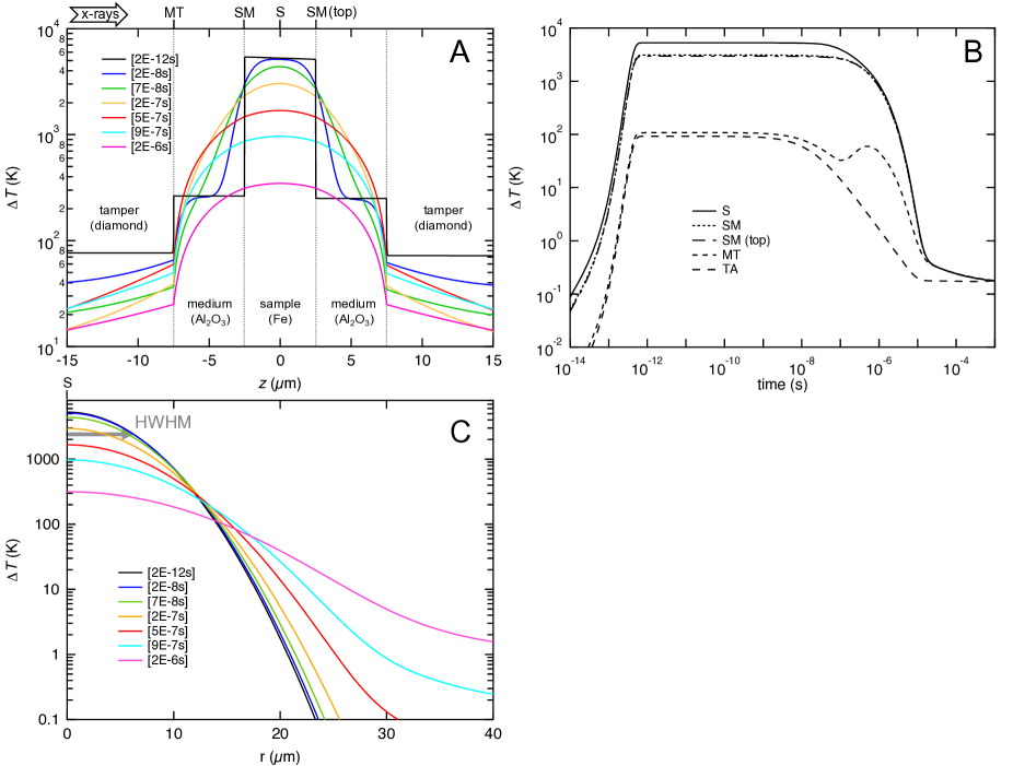
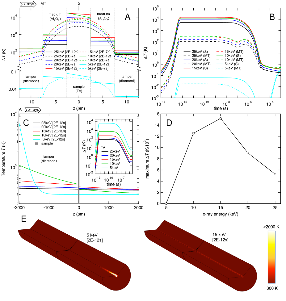
The baseline simulation, on which other simulations are perturbations, uses the standard target materials arrangement, radiation of 25 keV and a net pulse energy of 0.35 mJ (Fig. 2). A close-up view of the sample region (Fig. 3) shows the development of temperature gradients, from an initial state of nearly-constant temperature within layers (at given ) and discontinuities at layer interfaces. The diamond tamper in this case, by virtue of its high thermal conductivity, provides rapid quenching of the tamper itself by radial heat flow, while the sample region remains hot on longer timescales (Fig. 3). Initial radial gradients (imposed by the assumed Gaussian beam profile) are roughly preserved and somewhat broadened with time (Fig. 2C). Note the sudden rise in temperature at the medium-tamper interface just before s (Fig. 2B), corresponding to arrival of a heat wave from the sample moving across the medium.
III.1.2 Radiation variance: X-ray intensity
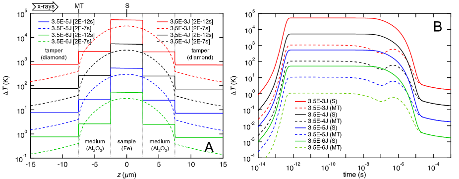
Varying the beam intensity (Fig. 4) proportionally shifts the thermal response of the target components, a result of the assumed linear absorption process and temperature insensitive material parameters. Thus, as rule of thumb, the temperature change at any x-ray fluence can be computed from a given simulation’s by scaling to the ratio of the x-ray fluencies, i.e.
| (17) |
III.1.3 Radiation variance: X-ray photon energy
Varying the x-ray wavelength (photon energy) through the hard x-ray range will vary the differential absorption in samples, and the temperature gradients established (Fig. 5). For lower energies (5 keV) the x-ray is absorbed almost entirely within the leading tamper layer (Fig. 5C,E) whereas harder x-rays (25 keV) will largely pass through the sample assembly without generating much heating. Homogeneity of heating depends on the x-ray energy, with harder x-rays producing superior initial homogeneity and lower energies greater initial asymmetry (Fig. 5A). In terms of providing an optimum heating solution, a 15 keV energy provides maximum sample heating, nearly homogeneous temperature in the sample and moderate but survivable heating in the tamper.
III.1.4 Geometry variance: Medium thickness
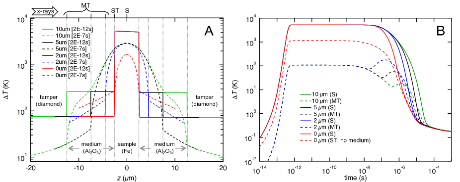
Without an interfacial medium layer between the sample and tamper, the temperature of the tamper is maximized by direct exposure to the hot sample; the sample is also cooled rapidly, but the tamper interface remains relatively hot (Fig. 6). Addition of even a thin medium layer reduces the temperature in the tamper considerably, while slowing sample cooling. When a medium is present, sample cooling behavior is insensitive to medium layer thickness, up to s, after which it varies considerably. Tamper cooling also proceeds more rapidly for a thicker medium layer. Arrival of the heat wave from the sample (Fig. 6B at s) can briefly drive tamper interfacial temperatures higher, possibly to above the initial temperature, though this temperature excursion remains below that which would occur in the absence of the medium. Thus, addition of even a thin medium layer can reduce heating of the tamper and potentially improve its stability.
III.1.5 Material variance: Sample
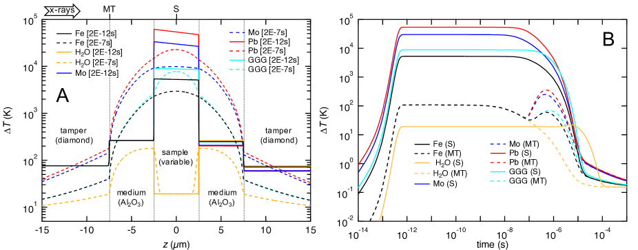
The samples were generally selected (Fig. 7) to exhibit the strongest heating of all target components, and are hence higher-Z materials, with the exception of water which has exceptionally weak heating, below all the other target components. Electrically insulating samples H2O and the heavy oxide Gd3Ga5O12 (which heats similar to Fe) have reduced thermal conductivities compared to the metals Fe, Mo, and Pb (Table 6), which slow their thermal evolution during the experiments, effectively maintaining the sample temperature even while metals cool off (Fig. 7). Heat waves incident on the tamper, at around s, cause large jumps in tamper surface temperature to well in excess of its initial temperature for hotter samples (Fig. 7B). For water, heat conducts into the sample from the hotter medium layers, leading to a late increase in temperature for this sample. At this x-ray energy (25 keV) the absorbance of each material is small such that the downstream temperatures are only weakly affected by the different samples (right side of Fig. 7A). Initial asymmetries in temperature in the sample area are more pronounced for the higher Z samples (Fig. 7A).

III.1.6 Material variance: Tamper
The tampers chosen for modeling (Fig. 8) generally show comparable x-ray transparency, with the exception of Al2O3 which has somewhat reduced transmission and hence results in lower sample temperature and higher tamper body temperatures. There is significant variance in the temperature and its evolution in the tamper bodies (Fig. 8C inset), but on shorter timescales sample conditions do not evolve differently for the different tampers (Fig. 8A-B). Significant differences in sample temperature evolution are observed only on long ( s) timescales (Fig. 8B). For the comparably low thermal conductivity plastic (Kapton) tamper, an accumulation of heat at the tamper interface is observed (Fig. 8A), which could promote tamper damage.
III.1.7 Material variance: Medium
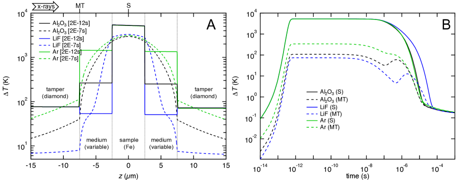
The interfacial medium layer material selected (Fig. 9) influences the sample temperature by controlling the rate of sample cooling, which is most notable on longer ( s) timescales. As all media chosen are of low x-ray absorbance, differences in performance are due mainly to the thermal conduction properties of the medium layers. Sample cooling is most sluggish for the lowest thermal conductivity medium (LiF), even though the initial temperature of this layer is also the lowest (which promotes more rapid cooling, all else being equal).
III.1.8 General features of target thermal evolution
Excluding the heat deposited by the x-ray irradiation, targets of the length scales described are effectively adiabatic on timescales up to 1-10 ns. As a consequence, considering irradiation on the timescales of typical FEL (10-100 fs) or synchrotron bunch (10-100 ps) sources, there should be little difference between peak temperature and subsequent thermal evolution, once LTE is achieved. Differences will appear only in the heating rate and potentially arise from nonlinear and ultrafast phenomena sensitive to this rate, but broadly, pulsed x-ray heating in the fs-ns range (Table 1) will produce essentially similar target responses, since these timescales do not allow significant cooling during the energy deposition phase. Thus for fast sources, the principal parameter for assessing the temperature following x-ray illumination is the total pulse energy and its spatial distribution. Therefore the thermal evolution calculations made here are relevant for pulses of any length, up to the adiabatic limit of 10 ns.
In these simulations interface temperatures between differentially heated surfaces are effectively constant on shorter (adiabatic) timescales. Immediately after heating, the interface achieves a temperature intermediate to that in the bulk of the contacting layers, defined in part by the bulk temperatures and in part by the layer thermal transport. These results are confirmed by the analytical solution for interfacial temperatures following rapid emplacement of an interfacial temperature discontinuityGrover and Urtiew (1974); McQueen and Isaak (1990). For assumed constant layer thermal conductivities (Sec. II.1.2), the interface temperature is given as
| (18) |
where subscripts indicate the contacting layers A and B. This closely predicts the simulated constant interface temperatures before cooling begins (after 10-8 s); e.g. in the baseline model at the leading interface between sample and medium, Eq. 18 predicts an initial interface temperature of K, compatible with the modeled value (Fig. 2) of 3400 K.
For targets involving an additional low-Z (medium) layer between the sample and the tamper, a late rise in tamper temperature occurs as the heat wave from the high-Z sample reaches the tamper surface. The associated heating is often relatively minor, even where extreme sample temperatures are reached: e.g. for 55,000 K in a Pb sample (Fig. 7) the heat pulse only raises the temperature at the tamper surface from 400 to 650 K. The timing and amplitude of the heat pulse is correlated with many properties of the system, showing, for example, a direct correlation with the thermal conduction properties of the materials. It can be observed that the arrival time of this pulse increases systematically with thermal diffusivity of the medium (Fig. 9 and Tables 5 and 6), i.e. it is fastest for a layer of dense argon ( m2/s), slowest for LiF ( m2/s), and intermediate for alumina ( m2/s). The pulse amplitude is lowest for higher thermal conductivity tampers and highest for the insulating tamper (Fig. 8).
Comparison of the temperature at the sample center and near the interface between the sample and its surroundings provides some indication of the temperature gradient occurring in the sample. On shorter timescales the temperature distribution in the sample is defined exclusively by the absorption profile (Fig. 5) with an asymmetric gradient in initial temperature along the beampath (axial direction) possible in low keV experiments (Fig. 5) or when using high-Z samples (Fig. 7). With time, the sample temperature becomes more symmetric in the axial direction, regardless of the initial heating symmetry, with the lowest values near interfaces and the center remaining warmer.
For harder x-rays (15 keV and above), peak temperatures in the low-Z tamper are generally produced adjacent to the sample layers, either immediately upon heating (due to interfacing with a hotter medium (Fig. 9) or sample (Fig. 6) layer, or after the heat wave from the cooling sample reaches the tamper (Figs. 6B, 7B, 8B). At lower keV, the hottest portion of the tamper is the leading free surface due to efficient absorption of the beam, however only at the lowest x-ray energy simulated (5 keV) is the tamper hotter than the sample (indeed, there is negligible heating in the sample in this instance).
III.2 Hydrodynamic Model Results
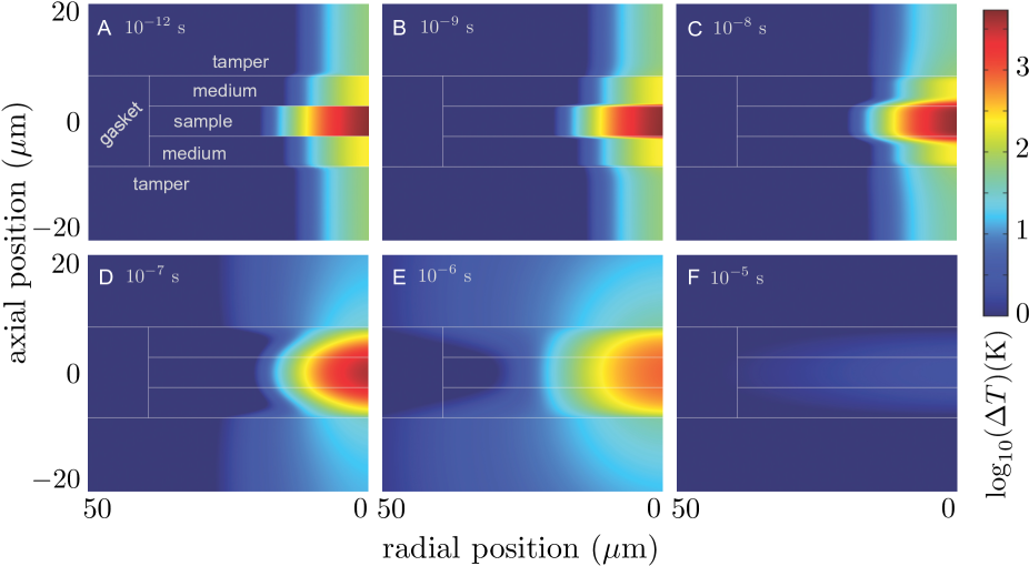
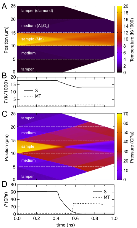
A representative hydrodynamic model of the initial thermomechanical evolution of a target after irradiation is shown in Fig. 10. Here a Mo sample, contained by an alumina medium and diamond tamper (c.f. Fig. 7), is heated with 25 keV x-rays at W/cm2 for 100 fs to peak temperature near K.
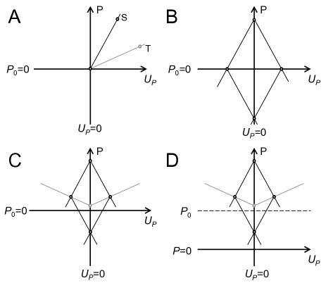
Coincident with the heating, the sample layer experiences an increase in pressure to 55-70 GPa, whereas minor heating in the surrounding layers produces weaker initial pressurization. Due to the differential heating and resulting differential pressures, waves of compression or release emerge from interfaces between the heated layersSentoku et al. (2007). In this hydrodynamic model, the hot, and hence high pressure sample layer undergoes release of pressure as it expands and compresses the cold surrounding layers, driving them to higher pressure. The sample expands beginning at its surfaces via an inward-moving release wave, while shock waves are driven outward through the medium and toward the tamper. While this initial process reduces the pressure in the sample, it is not to zero due to the presence of the medium and the requirement of impedance matching at the sample-medium interface (Fig. 11C). This also requires the corresponding shock pressure to be some fraction of the initial thermal pressurization.
The outward moving shocks reflect off the tampers and back toward the sample (at 0.6 ns), producing a stress maximum on the tamper comparable in magnitude to the initial thermal stress induced in the sample (Fig. 10D). A more compressible medium reduces this initial shock stress at the tamper for similar initial sample conditions. Meanwhile, the inward moving release waves in the sample layer interact in the target center, producing (beyond 0.5 ns) a stress minimum in the sample which essentially restores the initial (zero) pressure condition. These colliding release waves can also produce tensile stress in the targetIvanov and Zhigilei (2003) (Fig. 11C-D), which was seen in separate hyades simulations if using suitable mechanical equations of state for the sample layer, and keeping peak stress sufficiently low. Compression and release is nearly symmetric about the sample center in Fig. 10, due to near-homogenous heating of each layer at 25 keV; strong asymmetry occurs for inhomogeneous heating in other simulations (e.g. if lower x-ray energy is used).
As confirmed by the simulations, hydrodynamic timescales relevant to a target of this thickness are sufficiently large that LTE conditions can be assumed in the materials. The hydrodynamic processes are thus comparable to those in conventional shock experiments of durations of order nanoseconds, such as those produced by optical laser pulsesMcWilliams et al. (2010); Eggert et al. (2010); Falk et al. (2018); Ng et al. (2005); Kraus et al. (2017); Armstrong et al. (2010). In such experiments, assuming conditions of thermodynamic equilibrium (i.e. in which materials follow an equilibrium equation of state) is a reasonable approximation. Simple thermodynamic calculations can thus predict essential details of the hydrodynamics, and find results consistent with the numerical models. For example, the magnitude of initial pressure can be reasonably predicted as an isochoric thermal pressure, after Eq. 16. For the 17700 K temperature rise in the Mo foil, having GPa and K-1, Eq. 16 gives 70 GPa; this compares well with the 62 GPa initial pressure rise calculated using hyades (Fig. 10).
Dynamic stresses should largely relax in s, before heat conduction initiates but with permanent and potentially significant effects on the temperature distribution in the target. Both shock (adiabatic) and release (isentropic) processes modify temperatures (Fig 10A-B). The temperature in the medium and tamper are somewhat increased by shock, however more pronounced is the temperature reduction in the sample during its release. This expansion cooling can be described accurately with a thermodynamic model, taking an isentropic expansion (entropy constant) of the Grüneisen form
| (19) |
where is the specific volume. The Grüneisen parameter
| (20) |
where is the specific heat capacity at constant volume, is often found to follow the relationship
| (21) |
where the subscript ‘0’ indicates reference (here ambient) conditions and the exponent is of order 1. Taking starting conditions of temperature and volume as and , initial isochorically-heated equilibrium conditions and , and hydrodynamically-released conditions and , and assuming constant thermal expansivity and complete release of thermal pressure, we have
| (22) |
i.e. the volume of the expanded state is equivalent to that produced on isobaric heating to the same temperature. Taking we obtain
| (23) |
Solving for an initial temperature K in Mo, with (taking ), we obtain a release temperature of K (a reduction of 25%), in agreement with that calculated using hyades for this initial condition (Fig. 10). While this can have a potentially major effect on the starting temperature conditions for finite element models, the expansion cooling becomes negligible at lower temperatures, i.e. for Mo at 1000 K the expansion cooling is %.
As the inertial confinement time in such samples is in the range of picoseconds, radiation pulses significantly longer than the picosecond level will not produce shock waves or large pressure excursions, remaining at or close to the initial pressure.
IV DISCUSSION
IV.1 Pulse Train Response
Many high-power x-ray sources involve high-repetition-rate pulse trains, up to the MHz level (pulse separations in the range of hundreds of ns, Table 1), with even faster repetitions possible using, e.g. split delay lines. For sources operating with high repetition rate, faster than the thermal relaxation time of samples (of order 10 s in these models), accumulation of thermal energy during a pulse train may occur. It may be crucial to consider this energy deposition for serial x-ray measurement (e.g. crystallographyWiedorn et. al. (2018)) applications, even at lower power levels that may normally be considered non-invasive. For example, considering the lowest level of irradiation studied here (0.0035 mJ/pulse, Fig. 4) and assuming a pulse repetition rate of 4.5 MHz (220 ns between pulses, Table 1), the temperature increase between pulses (including heating and cooling) is K, implying it would take roughly 50 pulses for an Fe sample to be driven in a step-wise fashion to its melting point (1811 K) from room temperature, in 11 s, assuming the temperature increases linearly with time. As thermal pressures delivered during pulses have time to dissipate between pulses, concomitant with thermal expansion, this type of heating can be thought of as being nearly isobaric, though the transient thermal pressurization and expansion process itself may have effects on the sample state (Sec. III.2, Sec. IV.2.3), while residual thermal pressure is possible in well-confined samplesDewaele, Fiquet, and Gillet (1998).
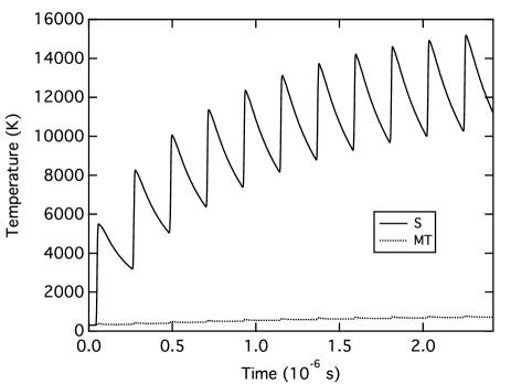
A representative finite element model of the stepwise heating due to x-ray pulse trains for the baseline experimental arrangement is shown in Fig. 12, using serial rather than single exposures at the standard (0.35 mJ/pulse) fluence, assuming a repetition rate of 4.5 MHz. The sample temperature grows in a sawtooth fashion, with each pulse producing a new temperature peak followed by a gradual cooling until the next pulse. Cooling rates increase with temperature, limiting achieved temperatures through a balance between heat added by the x-ray pulses, and energy loss by conduction between pulses, such that peak temperatures rise nonlinearly during the pulse train, and rapidly approach a limiting value. In this case the temperature maximum is about three times greater than that achieved following a single pulse. Similarly, at the lowest fluence (0.0035 mJ/pulse as used in the earlier estimate) the sample would never reach melting, remaining below 500 K in the limit.
Pulse train experiments may be useful for both probing and heating. For nominally noninvasive probing applications, extending the duration between pulses can reduce the heat accumulated in a fixed target, and ensure the sample temperature rise is minimized at the time of each probing. On longer timescales, the sample temperature at the time of probing is constant, so the data obtained can be treated as isothermal but at an elevated, saturation temperature (after the initial pulses during which stabilization occurs). For deliberate heating, minimizing pulse delay can increase the maximum achievable temperature, and the functional length of the pulse train may be the number of pulses required to reach a saturation value (e.g. 15 pulses for a 4.5 MHz train, Fig. 12).
IV.2 Target Damage and Mitigation
Either in a single- or multiple-exposure experiment, the target lifetime can be of central importance. In a traditional isochoric heating experiment on thin layered targets, the lifetime is set by hydrodynamic expansion of the hot target, occurring as the ions gain energy from electrons and expand into vapor. By confining the hot target in a tamper, this time can be increased. Use of very massive tampers surrounding a hotspot can lead to total confinement of even a dense plasma state, and reliable target survivalVailionis et al. (2011); McWilliams et al. (2015). In what follows, basic mechanisms for target failure and their mitigation for long-duration and serial experiments are discussed. The considerations here apply principally to the effects of a single pulse, inasmuch as the primary damage should occur during the pulse and subsequent thermomechanical relaxation.
IV.2.1 Thermal damage
Significant damage in targets can result from thermal effects, which include reversible and irreversible phase transformation (e.g. melting), reaction, strength reduction (i.e. in the tamper), and for free surfaces, or at gaps, the possibility of vaporization. While some of these effects are certain to occur in higher-Z (strongly heated) samples, the survival of the target assembly will likely depend on tamper integrity. The temperature at the surfaces of the tamper generally determine the peak temperatures to which the tampers are subject, and thus the ability of tampers to survive the thermo-mechanical cycle and successfully confine the sample throughout. This includes the tamper surfaces facing the sample, heated by close contact with a hot sample layer, and the free surface facing the beam, heated by peak fluence (Figs 2 – 10).
Many of the temperature conditions found in these simulations are in principal such that the tampers can survive irradiation. Except for softer x-rays (Fig. 5), low-thermal conductivity tampers (Fig. 8) or no interfacial layer (Fig. 6), temperatures remain below probable damage points of the tamper in these experiments even for significant heating in the sample layer (by 103-104 K). For the high-thermal conductivity tampers, the tamper temperature remains below graphitization and oxidation points for diamond (1000-2000 K), the sublimation point for graphite (4000 K) and melting points for Be and Al2O3(1500-2300 K), for 25 keV radiation (Fig. 8). For the standard experimental configuration (diamond-alumina-iron and 25 keV x-rays), the tamper begins with only about 2% of the temperature change in the sample (Fig 4) and never exceeds this as the target cools. Even for temperatures exceeding 50,000 K in any sample, diamond tamper temperatures need not exceed 600 -1400 K (Figs 4 and 7), low enough to prevent thermal damage, particularly for brief heating. In contrast, the low thermal conductivity plastic tamper (Fig. 8) leads to elevated thermal confinement near the tamper interface with the sample region, and heating of the tamper surface up to 1200 K for a sample temperature of 6000 K, well beyond the thermal degradation point of the material (670 K for Kapton).

IV.2.2 Radiation damage
Ultrahigh intensity laser sources can have substantial direct influence on materials including radiative damage and electronic excitation: insulators can be rapidly and transiently transformed to metalsSchiffrin et al. (2012), bonds can be disruptedZastrau et al. (2014), and structural transformations that normally would be sluggish can occur instantaneouslyMedvedev, Jeschke, and Ziaja (2013). Such ‘non-thermal’ radiation effects can be quantified by the amount of energy absorbed per atom, . From Eq. 4, integrating over the pulse, and ignoring beam attenuations, the maximum of this quantity is
| (24) |
where is atomic mass (Eq. 14) and peak energy density per area is (Eq. 11). Use of this criterion then leads to rough constraints on acceptable irradiation conditions.
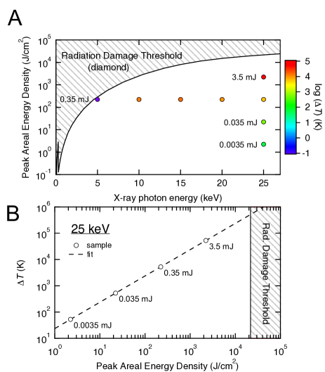
Considering again tamper integrity, direct radiative ablation is possible at free surfaces where unconfined atoms may easily escape the target, at 1 eV; however, for the low-Z tampers considered here, such as Be and C polymorphs, this limit is not easily reachedRoth et al. (2018). For diamond, nonthermal breakdown of diamond to graphite occurs at relatively lower absorbed energy, 0.7 eV/atom Medvedev, Jeschke, and Ziaja (2013); Roth et al. (2018). Even with this more conservative criterion, modeled irradiation conditions remain below the nonthermal damage threshold for diamondMedvedev, Jeschke, and Ziaja (2013) (Fig. 13A) except possibly at the lowest x-ray energy (5 keV) where, due to considerable direct heating from the x-ray beam (Fig. 5), the overall damage threshold is likely to be at even lower fluence. At 25 keV (Fig. 13B), a diamond tamper could survive irradiation up to iron sample temperatures of 40 eV ( K), and higher-Z sample temperatures in the 100 eV range (c.f. Fig. 7); tamper damage risk from heating and shock is likely to be more critical at such conditions. In summary, direct radiation damage may not be a major factor in target survival and performance. An effective lower limit on beam diameter to avoid radiation damage in diamond is given in Fig. 14.
IV.2.3 Thermo-mechanical damage
With the rapid, bulk heating of samples occurring faster than pressure wave propagation in our simulations (i.e. ), thermal pressure develops as a consequence of heating. The large mechanical stresses associated with target heating can introduce immediate or cumulative damage to targets, including irreversible deformations, flow, fracturing, delamination at interfaces, and spall. Thus, target survival after a single pulse or series of pulses will depend on the integrity of the target under mechanical stresses as temperature and pressure are raised, and as pressures dissipate hydrodynamically as stress differentials relax (Fig. 10). The system can exhibit a complex thermomechanical evolution as it moves toward equilibrium if surrounding tampers are sufficiently strong to resist free hydrodynamic expansion. Mechanical stresses could act in conjunction with direct thermal effects including softening, melting, and vaporization to promote damage.
The magnitudes of mechanical stress initially generated in the target (Eq. 16) will be similar to those associated with subsequent pressure waves. In the present examples, while this value can be large, relatively lower stress is applied to the surrounding materials and tampers due to impedance matching requirements. In our example, for the 60 GPa initial stress in the Mo sample, shock waves forming in conjunction with the release of the hot sample layer and striking (and reverberating from) the tamper (diamond in this instance) are 30 GPa in amplitude (Fig. 10). While tamper temperature is increased somewhat by this shock, in terms of damage threshold it is the pressure perturbation will likely cause the immediate (mechanical) damage. Notably, the diamond tamper in this case can withstand the shock wave (which falls below the dynamic yielding pointMcWilliams et al. (2010)) as well as the subsequent heat wave (Fig. 7). However, shock waves of this amplitude could severely damage other tampers. As the pressure medium controls the shock amplitude, softer media could be used to minimize the shock stress, while complete suppression of shock could be achieved using pulses with durations exceeding the hydrodynamic relaxation times (e.g. synchrotron bunch pulses, Table 1).
IV.3 Anvil Cell Configuration
As the target configuration discussed here is broadly identical to that of static high pressure cells, this application is considered in detail below. In an anvil cell type design, the sample is configured to withstand high stresses in the sample area via confinement by thick, hard materials. Diamond anvils provide unmatched capabilities for pressure application and resistance, for up to 1000 GPaDubrovinsky et al. (2012), while other strong, low-Z candidates for high-strength tamper-anvils include sapphire (single crystal Al2O3) and Moissanite (SiC)Mao and Mao (2007).
The prior considerations for limiting target damage suggest that improving sample confinement, i.e. using a pressure cell configuration, could enhance target stability and survival. In this configuration, thermal expansion of the hot sample is limited Dewaele, Fiquet, and Gillet (1998) ensuring the material remains at or near its initial density regardless of heating. Cracks or voids which can be present in multilayer target assemblies or ordinarily develop due to thermal stresses can be suppressed. The ability of anvil cells to resist the heating and associated mechanical stresses in hot samples have long been demonstrated using infrared lasers to heat samples, to temperatures in the range of several eV, over timescales of microseconds and longerDewaele, Fiquet, and Gillet (1998); McWilliams et al. (2015); Goncharov et al. (2010). With similar conditions of temperature, pressure, and timescale found in the present x-ray heating simulations, many advantages and techniques of the anvil cell configuration may be useful in thickly-tamped target experiments generally.
In one possible experiment, a tamped sample could be placed under some small initial stress (to ensure good initial confinement, and void elimination). Thermal stresses introduced by x-ray heating could be controlled by the anvil’s high strength and potential stress resistance. So long as the anvils can withstand the additional mechanical stresses (on the order of GPa or higher for conditions considered here, Sec. III.2) and any heating (Sec. III.1), the target could be stabilized indefinitely. The anvil cell provides a built in way to safely relieve thermal stresses in samples to a mechanical equilibrium confinement stateDewaele, Fiquet, and Gillet (1998) without hydrodynamic expansion, solving a principal issue in tamped laser-driven targets that may only be partially mitigated by tamping alone. The extended target stabilization would permit studies over a wide range of timescales, accessing phenomena including electron-ion thermalization, structural transitions and thermal conduction, and enable repeated exposures of the same sample on arbitrary timescales, and sample recovery. This approach would require some apparatus to apply a compressive force across the target, as in a standard pressure cell configuration, with suitable windows for admittance and observation of radiation.
The ability to pre-compress samples to elevated densities can also provide, in conjunction with x-ray irradiation, a route to studying laser-plasma interactions and warm dense matter at conditions of very high density, exceeding that of conventional solid states. Static pre-compression of matter to hundreds of GPa confining pressure, or larger using modern double-stage anvilsDubrovinsky et al. (2012), is a widely used method, compatible with a variety of strategies to further modulate sample conditions (e.g. temperature) and probe sample properties at extremes. Our models demonstrate that coupling a high density sample with intense x-ray irradiation on modern light sources can offer a new approach for exploring ultra-dense and hot states, complementary with dynamic compression and traditional optical-laser-heated DAC, in terms of achievable pressure-temperature-timescale conditions. Indeed, x-ray heating may serve as an alternative to optical laser-heatingMao and Mao (2007); Dewaele, Fiquet, and Gillet (1998); Goncharov et al. (2010); McWilliams et al. (2015) of anvil cells, with the modeled pulsed x-ray heating of samples closely resembling pulsed optical laser heating approachesGoncharov et al. (2010); McWilliams et al. (2015); Konôpková et al. (2016); Goncharov et al. (2012), with several key differences. Optical heating techniques produce large temperature gradients in samples, i.e. where heat must conduct from a heated surface, and are susceptible to unpredictable coupling related to surface or sample properties; furthermore probes must be carefully aligned with the heated spots. Hard x-ray heating can in contrast provide homogenous temperatures in the sample bulk on rapid timescalesNagler et al. (2009), simple coupling with the sample, and automatic alignment of heating and x-ray probe beams. X-ray heating may be particularly useful where introduction of optical laser energy to samples is impractical or impossible, such as where optically opaque anvils are used, e.g. in double-stage anvilDubrovinsky et al. (2012) or multi-anvil applications, where the optical damage threshold of anvils may be exceeded in high-energy applicationsArmstrong et al. (2010), or where nominally transparent insulating media transform to opaque conductors during heatingMcWilliams et al. (2015).
Addition of pressure could, at least for the sample interfacing region, serve to elevate the damage thresholds for a diamond tamper, both in terms of its thermal resistance and mechanical resistance. Thermal graphitization is prevented above 13 GPa where diamond becomes the stable structure of carbon, whereas the melting temperature of diamond at these conditions exceeds 4000 KEggert et al. (2010). Confining pressure also increases the strength of diamondMcWilliams et al. (2010), a fact employed in modern anvil cell designs to enhance the potential stress resistanceDubrovinsky et al. (2012).
Fig. 15 compares two different types of geometry used in our simulations: the first is the cylindrical geometry used in the main simulations, and the second is a representation of an anvil cell. For similar peak temperatures, there is little difference between the simplified cylindrical model and the more complete model in terms of the temperature evolution of the sample area. Thus finite-element calculations using the present simple geometry accurately describe the anvil cell design.
V CONCLUSIONS
This study describes the thermo-mechanical response of macroscale targets subjected to irradiation by intense, brief x-ray pulses, similar to those now produced by the current generation of x-ray free electron lasers. These targets use thick, light-element tamper or anvil layers, which are transparent at hard x-ray energies, to confine a thin target assembly, comprising one or more layers which may be strongly absorbing to x-ray radiation. The thermal and mechanical evolution of the x-ray heated target after the rapid deposition of heat is treated using finite-element and radiation-hydrodynamics calculations. We find that conventional hydrodynamics, classical diffusive heat transfer, and equilibrium thermodynamics can accurately treat the principal thermo-mechanical phenomena for the length and time scales characteristic of such large targets.
Conditions achieved in the most extreme experiments simulated fall within the regime of warm dense matter, i.e. conditions near or above solid density and temperatures exceeding several eV, where ratios of Coulomb interaction energy to thermal kinetic energy (the coupling parameter) and of Fermi energy to thermal energy (the degeneracy parameter) approach unity. That these conditions could be sustained for up to microsecond timescales using suitable target configurations offers a potential way to study properties of warm dense matter under total thermodynamic equilibrium conditions, on timescales exceeding those of modern experiments that use laser-driven shock waves or unconfined isochoric heating. Using thick tampers to apply initial pressure on samples and taking advantage of serial irradiation can enable further exploration of novel regimes of density, temperature, and timescale in warm dense matter. Target survival over one or more exposures is controlled by targets’ potential resistance to temperatures on the order of an eV (thousands of degrees Kelvin), mechanical stress close to one million atmospheres (100 GPa), and radiation levels close to damage thresholds, all found to be survivable depending on target design.
For thick targets of the considered design (m-thick samples with mm-thick tampers), the thermal response due to intense x-ray illumination should be similar at different facilities offering sub-nanosecond pulses, including modern free electron laser and synchrotron sources. Due to the thermal inertia of samples of this scale, temperatures achieved and cooling behavior are not strongly dependent on pulse lengths, but on total energy dose. Thus modern synchrotron sources with 100 ps pulse duration may produce a similar level of heating to that at an XFEL with 100 fs pulses, for equivalent pulse energy. Heat accumulation over pulse trains with MHz repetition rates characteristic of such facilities can lead to further temperature rise, though this effect is somewhat mitigated by equilibrium between heating and cooling that leads to effectively isothermal experiments on longer timescales. Thus, consideration of x-ray heating effects may be necessary even in nominally non-invasive x-ray measurements at many modern, high brightness, high repetition-rate x-ray sources, including synchrotron facilities. Certain related processes could be more sensitive to the radiation intensity and pulse duration, including shock-wave generation, which would occur under 100-fs XFEL but not 100-ps synchrotron irradiation.
The multilayer target configuration discussed here is informed by, and mimics, the configuration of a static high pressure anvil system, of which the diamond-anvil cell uniaxial press is the most relevant. Anvil cells have the ability of preparing initial states of elevated density and pressure in samples, including different structural states, prior to excitation to more extreme states; their wide use in preparing samples for shock-wave compressionJeanloz et al. (2007); Armstrong et al. (2010) and near-isochoric optical laser heatingDewaele, Fiquet, and Gillet (1998); Goncharov et al. (2010); McWilliams et al. (2015) experiments suggests many possibilities for accessing otherwise unreachable states of matter with x-ray heating, and for enabling diagnosis of these states by a wide range of radiation types. While experience with conventional optical laser heating of anvil cells is relevant, x-ray heating has the potential to bring new advantages for heating pre-compressed matter, including direct volumetric heating, automatic x-ray probe alignment with heated areas, and insensitivity to target optical thresholds. The confinement afforded through an anvil cell design is another way to stabilize tamped targets against thermomechanical stress generally and extend experimental lifetimes by limiting them with conductive rather than hydrodynamic dissipation, and ensure target survival for continued exposure and recovery of samples from extremes.
Ultimately experiments must be performed to assess the accuracy of the models developed here, as are currently possible at modern x-ray sources. Further improvements in these models will likely be required to compare with experiments, including coupling of thermomechanical and thermal conductive processes and more accurate treatment of radiation coupling in the sample, which are likely to be essential at higher radiation intensities.
ACKNOWLEDGEMENTS
This work was supported by an EPSRC First Grant EP/P024513/1, CONACyT and UAEMéx, and Leverhulme Trust grant RPG-2017-035. Thanks to Y. Ping for providing hyades code, and J. Wark, U. Zastrau, S. Pascarelli, V. Lyamanev, C. Strohm, S. Toleikis, and J. Eggert for helpful discussions.
References
- Ng et al. (2005) A. Ng, T. Ao, F. Perrot, M. Dharma-Wardana, and M. Foord, Laser and Particle Beams 23, 527 (2005).
- Sentoku et al. (2007) Y. Sentoku, A. J. Kemp, R. Presura, M. S. Bakeman, and T. E. Cowan, Physics of Plasmas 14, 122701 (2007).
- Fletcher et al. (2014) L. B. Fletcher, H. J. Lee, B. Barbrel, M. Gauthier, E. Galtier, B. Nagler, T. Döppner, S. LePape, T. Ma, A. Pak, D. Turnbull, T. White, G. Gregori, M. Wei, R. W. Falcone, P. Heimann, U. Zastrau, J. B. Hastings, and S. H. Glenzer, Review of Scientific Instruments 85, 6 (2014).
- Patel et al. (2003) P. K. Patel, A. J. Mackinnon, M. H. Key, T. E. Cowan, M. E. Foord, M. Allen, D. F. Price, H. Ruhl, P. T. Springer, and R. Stephens, Phys. Rev. Lett. 91, 125004 (2003).
- Gregori et al. (2005) G. Gregori, S. B. Hansen, R. Clarke, R. Heathcote, M. H. Key, J. King, R. I. Klein, N. Izumi, A. J. Mackinnon, S. J. Moon, H. Park, J. Pasley, N. Patel, P. K. Patel, B. A. Remington, D. D. Ryutov, R. Shepherd, R. A. Snavely, S. C. Wilks, B. B. Zhang, and S. H. Glenzer, Contributions to Plasma Physics 45, 284 (2005).
- Ivanov and Zhigilei (2003) D. S. Ivanov and L. V. Zhigilei, Phys. Rev. B 68, 064114 (2003).
- Lévy et al. (2015) A. Lévy, P. Audebert, R. Shepherd, J. Dunn, M. Cammarata, O. Ciricosta, F. Deneuville, F. Dorchies, M. Fajardo, C. Fourment, D. Fritz, J. Fuchs, J. Gaudin, M. Gauthier, A. Graf, H. J. Lee, H. Lemke, B. Nagler, J. Park, O. Peyrusse, A. B. Steel, S. M. Vinko, J. S. Wark, G. O. Williams, D. Zhu, and R. W. Lee, Physics of Plasmas 22, 030703 (2015).
- White et al. (2014) T. G. White, N. J. Hartley, B. Borm, B. J. B. Crowley, J. W. O. Harris, D. C. Hochhaus, T. Kaempfer, K. Li, P. Neumayer, L. K. Pattison, F. Pfeifer, S. Richardson, A. P. L. Robinson, I. Uschmann, and G. Gregori, Phys. Rev. Lett. 112, 145005 (2014).
- Zastrau et al. (2014) U. Zastrau, P. Sperling, A. Becker, T. Bornath, R. Bredow, T. Döppner, S. Dziarzhytski, T. Fennel, L. B. Fletcher, E. Förster, C. Fortmann, S. H. Glenzer, S. Göde, G. Gregori, M. Harmand, V. Hilbert, B. Holst, T. Laarmann, H. J. Lee, T. Ma, J. P. Mithen, R. Mitzner, C. D. Murphy, M. Nakatsutsumi, P. Neumayer, A. Przystawik, S. Roling, M. Schulz, B. Siemer, S. Skruszewicz, J. Tiggesbäumker, S. Toleikis, T. Tschentscher, T. White, M. Wöstmann, H. Zacharias, and R. Redmer, Phys. Rev. E 90, 013104 (2014).
- Mostovych and Chan (1997) A. N. Mostovych and Y. Chan, Phys. Rev. Lett. 79, 5094 (1997).
- Ping et al. (2015) Y. Ping, A. Fernandez-Panella, H. Sio, A. Correa, R. Shepherd, O. Landen, R. A. London, P. A. Sterne, H. D. Whitley, D. Fratanduono, T. R. Boehly, and G. W. Collins, Physics of Plasmas 22, 092701 (2015).
- Tahir et al. (2017) N. A. Tahir, I. V. Lomonosov, B. Borm, A. R. Piriz, A. Shutov, P. Neumayer, V. Bagnoud, and S. A. Piriz, The Astrophysical Journal Supplement Series 232, 1 (2017).
- McWilliams et al. (2010) R. S. McWilliams, J. H. Eggert, D. G. Hicks, D. K. Bradley, P. M. Celliers, D. K. Spaulding, T. R. Boehly, G. W. Collins, and R. Jeanloz, Physical Review B 81, 19 (2010).
- Kraus et al. (2017) D. Kraus, J. Vorberger, A. Pak, N. J. Hartley, L. B. Fletcher, S. Frydrych, E. Galtier, E. J. Gamboa, D. O. Gericke, S. Glenzer, E. Granados, M. J. MacDonald, A. J. MacKinnon, E. E. McBride, I. Nam, P. Neumayer, M. Roth, A. M. Saunders, A. K. Schuster, P. Sun, T. van Driel, T. Döppner, and R. W. Falcone, Nature Astronomy 1, 606 (2017).
- Falk et al. (2018) K. Falk, M. Holec, C. J. Fontes, C. L. Fryer, C. W. Greeff, H. M. Johns, D. S. Montgomery, D. W. Schmidt, and M. Šmíd, Phys. Rev. Lett. 120, 025002 (2018).
- Eggert et al. (2010) J. H. Eggert, D. G. Hicks, P. M. Celliers, D. K. Bradley, R. S. McWilliams, R. Jeanloz, J. E. Miller, T. R. Boehly, and G. W. Collins, Nat Phys 6, 40 (2010).
- Goncharov et al. (2010) A. F. Goncharov, V. B. Prakapenka, V. V. Struzhkin, I. Kantor, M. L. Rivers, and D. A. Dalton, Review of Scientific Instruments 81, 113902 (2010).
- Goncharov et al. (2012) A. F. Goncharov, M. Wong, D. Allen Dalton, J. G. O. Ojwang, V. V. Struzhkin, Z. Konôpková, and P. Lazor, Journal of Applied Physics 111, 112609 (2012).
- McWilliams et al. (2015) R. McWilliams, D. A. Dalton, Z. Konôpková, M. F. Mahmood, and A. F. Goncharov, Proceedings of the National Academy of Sciences 112, 7925 (2015).
- Konôpková et al. (2016) Z. Konôpková, R. S. McWilliams, N. Gomez-Perez, and A. F. Goncharov, Nature 534, 99 (2016).
- Ping et al. (2006) Y. Ping, D. Hanson, I. Koslow, T. Ogitsu, D. Prendergast, E. Schwegler, G. Collins, and A. Ng, Phys. Rev. Lett. 96, 255003 (2006).
- Vailionis et al. (2011) A. Vailionis, E. G. Gamaly, V. Mizeikis, W. Yang, A. V. Rode, and S. Juodkazis, Nat Commun 2, 445 (2011).
- Johnson et al. (2005) S. L. Johnson, P. A. Heimann, A. G. MacPhee, A. M. Lindenberg, O. R. Monteiro, Z. Chang, R. W. Lee, and R. W. Falcone, Phys. Rev. Lett. 94, 057407 (2005).
- Bailey et al. (2003) J. Bailey, P. Arnault, T. Blenski, G. Dejonghe, O. Peyrusse, J. MacFarlane, R. Mancini, M. Cuneo, D. Nielsen, and G. Rochau, Journal of Quantitative Spectroscopy and Radiative Transfer 81, 31 (2003), radiative Properties of Hot Dense Matter.
- Zastrau et al. (2008) U. Zastrau, C. Fortmann, R. R. Fäustlin, L. F. Cao, T. Döppner, S. Düsterer, S. H. Glenzer, G. Gregori, T. Laarmann, H. J. Lee, A. Przystawik, P. Radcliffe, H. Reinholz, G. Röpke, R. Thiele, J. Tiggesbäumker, N. X. Truong, S. Toleikis, I. Uschmann, A. Wierling, T. Tschentscher, E. Förster, and R. Redmer, Phys. Rev. E 78, 066406 (2008).
- Nagler et al. (2009) B. Nagler, U. Zastrau, R. R. Faustlin, S. M. Vinko, T. Whitcher, A. J. Nelson, R. Sobierajski, J. Krzywinski, J. Chalupsky, E. Abreu, S. Bajt, T. Bornath, T. Burian, H. Chapman, J. Cihelka, T. Döppner, S. Dusterer, T. Dezelzainis, M. Fajardo, E. Forster, C. Fortmann, E. Galtier, S. H. Glenzer, S. Gode, G. Gregori, V. Hajkova, P. Heimann, L. Juha, M. Jurek, F. Y. Khattak, A. R. Khorsand, D. Klinger, M. Kozlova, T. Laarmann, H. J. Lee, R. W. Lee, K.-H. Meiwes-Broer, P. Mercere, W. J. Murphy, A. Przystawik, R. Redmer, H. Reinholz, D. Riley, G. Roppke, F. Rosmej, K. Saksl, R. Schott, R. Thiele, J. Tiggesbaumker, S. Toleikis, T. Tschentscher, I. Uschmann, H. J. Vollmer, and J. S. Wark, Nature Physics 5, 693 (2009).
- Vinko et al. (2012) S. M. Vinko, O. Ciricosta, B. I. Cho, K. Engelhorn, H. K. Chung, C. R. D. Brown, T. Burian, J. Chalupsky, R. W. Falcone, C. Graves, V. Hajkova, A. Higginbotham, L. Juha, J. Krzywinski, H. J. Lee, M. Messerschmidt, C. D. Murphy, Y. Ping, A. Scherz, W. Schlotter, S. Toleikis, J. J. Turner, L. Vysin, T. Wang, B. Wu, U. Zastrau, D. Zhu, R. W. Lee, P. A. Heimann, B. Nagler, and J. S. Wark, Nature 482, 59 (2012).
- Glenzer et al. (2016) S. H. Glenzer, L. B. Fletcher, E. Galtier, B. Nagler, R. Alonso-Mori, B. Barbrel, S. B. Brown, D. A. Chapman, Z. Chen, C. B. Curry, F. Fiuza, E. Gamboa, M. Gauthier, D. O. Gericke, A. Gleason, S. Goede, E. Granados, P. Heimann, J. Kim, D. Kraus, M. J. MacDonald, A. J. Mackinnon, R. Mishra, A. Ravasio, C. Roedel, P. Sperling, W. Schumaker, Y. Y. Tsui, J. Vorberger, U. Zastrau, A. Fry, W. E. White, J. B. Hasting, and H. J. Lee, Journal of Physics B: Atomic, Molecular and Optical Physics 49, 092001 (2016).
- Saunders et al. (2018) A. M. Saunders, B. Lahmann, G. Sutcliffe, J. A. Frenje, R. W. Falcone, and T. Döppner, Phys. Rev. E 98, 063206 (2018).
- Linac Coherent Light Source (2017) Linac Coherent Light Source, “MEC Specifications,” (2017), https://lcls.slac.stanford.edu/instruments/mec/specifications, Last accessed 07-2018.
- LCL (2015) “LCLS-II final design report, rep. LCLSII-1.1-DR-0251,” Tech. Rep. (SLAC, Menlo Park, USA, 2015).
- Raubenheimer (2018) T. Raubenheimer, in Proc. 60th ICFA Advanced Beam Dynamics Workshop (FLS’18), Shanghai, China, 5-9 March 2018, ICFA Advanced Beam Dynamics Workshop No. 60 (JACoW Publishing, Geneva, Switzerland, 2018) pp. 6–11, https://doi.org/10.18429/JACoW-FLS2018-MOP1WA02.
- Yabashi, Tanaka, and Ishikawa (2015) M. Yabashi, H. Tanaka, and T. Ishikawa, Journal of Synchrotron Radiation 22, 477 (2015).
- Garbarino (2017) G. Garbarino, “Id27, an advanced high flux XRD beamline for science under extreme conditions: present and future,” (2017), presentation at the 55th EHPRG Meeting, Poznań, Poland.
- Celliers et al. (2018) P. M. Celliers, M. Millot, S. Brygoo, R. S. McWilliams, D. E. Fratanduono, J. R. Rygg, A. F. Goncharov, P. Loubeyre, J. H. Eggert, J. L. Peterson, N. B. Meezan, S. Le Pape, G. W. Collins, R. Jeanloz, and R. J. Hemley, Science 361, 677 (2018).
- Schöttler and Redmer (2018) M. Schöttler and R. Redmer, Phys. Rev. Lett. 120, 115703 (2018).
- Medvedev, Jeschke, and Ziaja (2013) N. Medvedev, H. O. Jeschke, and B. Ziaja, Physical Review B 88, 224304 (2013).
- Mao and Mao (2007) H.-K. Mao and W. Mao, in Treatise on Geophysics, edited by G. Schubert (Elsevier, Amsterdam, 2007) pp. 231 – 267.
- Jenei et al. (2019) Z. Jenei, H. P. Liermann, R. Husband, A. S. J. M ndez, D. Pennicard, H. Marquardt, E. F. O’Bannon, A. Pakhomova, Z. Konôpková, K. Glazyrin, M. Wendt, S. Wenz, E. E. McBride, W. Morgenroth, B. Winkler, A. Rothkirch, M. Hanfland, and W. J. Evans, Review of Scientific Instruments 90, 065114 (2019).
- Dewaele, Fiquet, and Gillet (1998) A. Dewaele, G. Fiquet, and P. Gillet, Review of Scientific Instruments 69, 2421 (1998).
- Sinn (2007) H. Sinn, HASYLAB Annual Report (2007).
- Roth et al. (2018) T. Roth, W. Freund, U. Boesenberg, G. Carini, S. Song, G. Lefeuvre, A. Goikhman, M. Fischer, M. Schreck, J. Grunert, and A. Madsen, Journal of Synchrotron Radiation 25, 177 (2018).
- Gomez-Perez, Rodriguez, and McWilliams (2017) N. Gomez-Perez, J. F. Rodriguez, and R. S. McWilliams, Journal of Applied Physics 121, 145904 (2017).
- Loveday, McMahon, and Nelmes (1990) J. S. Loveday, M. I. McMahon, and R. J. Nelmes, Journal of Applied Crystallography 23, 392 (1990).
- Jeanloz et al. (2007) R. Jeanloz, P. M. Celliers, G. W. Collins, J. H. Eggert, K. K. M. Lee, R. S. McWilliams, S. Brygoo, and P. Loubeyre, Proceedings of the National Academy of Sciences of the United States of America 104, 9172 (2007).
- Dubrovinsky et al. (2012) L. Dubrovinsky, N. Dubrovinskaia, V. B. Prakapenka, and A. M. Abakumov, Nature Communications 3, 7 (2012).
- Larsen and Lane (1994) J. T. Larsen and S. M. Lane, Journal of Quantitative Spectroscopy and Radiative Transfer 51, 179 (1994).
- Grover and Urtiew (1974) R. Grover and P. A. Urtiew, Journal of Applied Physics 45, 146 (1974).
- McQueen and Isaak (1990) R. G. McQueen and D. G. Isaak, Journal of Geophysical Research-Solid Earth and Planets 95, 21753 (1990).
- Armstrong et al. (2010) M. R. Armstrong, J. C. Crowhurst, S. Bastea, and J. M. Zaug, Journal of Applied Physics 108, 9 (2010).
- Wiedorn et. al. (2018) M. O. Wiedorn et. al., Nature Communications 9, 4025 (2018).
- Schiffrin et al. (2012) A. Schiffrin, T. Paasch-Colberg, N. Karpowicz, V. Apalkov, D. Gerster, S. M hlbrandt, M. Korbman, J. Reichert, M. Schultze, S. Holzner, J. V. Barth, R. Kienberger, R. Ernstorfer, V. S. Yakovlev, M. I. Stockman, and F. Krausz, Nature 493, 70 (2012).