Understanding End-to-End Effects of Channel Dynamics in Millimeter Wave 5G New Radio
Abstract
A critical challenge for wireless communications in the millimeter wave (mmWave) bands is blockage. MmWave signals suffer significant penetration losses from many common materials and objects, and small changes in the position of obstacles in the environment can cause large variations in the channel quality. This paper provides a measurement-based study of the effects of human blockage on an end-to-end application over a mmWave cellular link. A phased array system is used to measure the channel in multiple directions almost simultaneously in a realistic indoor scenario. The measurements are integrated into a detailed ns-3 simulation that models both the latest 3GPP New Radio beam search procedure as well as the internet protocol stack. The measurement-based simulation illustrates how recovery from blockage depends on the path diversity and beam search.
Index Terms:
Millimeter wave communications, dynamics, blockage, TCP, ns-3I Introduction
The millimeter wave (mmWave) bands and other frequencies above 6 GHz have become a key component of the emerging fifth generation (5G) cellular standards [1, 2, 3]. These frequencies offer vastly greater bandwidths than what is available in the conventional sub-6 GHz bands providing the potential to meet the massive mobile broadband and ultra-low latency requirements of the 5G vision [4]. However, a key challenge for the use of the mmWave bands in mobile applications is blockage: MmWave signals are significantly more vulnerable than signals at conventional frequencies to blockage by many common obstacles and materials [5].
In addition to the reduced coverage and range, the susceptibility to blockage of mmWave signals can result in highly variable link quality. Small motion of the handset relative to blockers and obstacles in the environment (including the hand or body) can result in dramatic swings in received power. The effects of blockage are complicated by the directional nature of the transmission in the mmWave frequencies. In cellular applications, mmWave signals will be transmitted and received in highly directional beams to overcome the high isotropic path loss in these frequencies. Blockage may be mitigated by finding alternate unblocked directions of communication. However, the performance of these techniques depends on the spatial diversity of the channel, the latency in beam tracking protocols and signal processing algorithms as well as the application and transport-layer effects of disruptions in link quality while alternate paths are being discovered.
The broad purpose of this paper is to provide an end-to-end perspective on the effects of blockage in 5G mmWave cellular systems. In particular, we evaluate the interaction of three underlying processes operating at different levels in the protocol stack:
-
•
Experimentally measured channel dynamics: Building on our measurement system in [6], we experimentally measure blockage in a complex, but realistic, blockage scenario in a home entertainment-type setting. Importantly, our measurement system can measure the channel in multiple directions nearly simultaneously, thereby providing a complete spatial and temporal trace of the channel.
-
•
3GPP NR beam search: The channel measurements are then incorporated into a detailed ns-3 based simulation [7, 8] along with the latest 3GPP New Radio (NR) standard [1]. The simulation accurately models the beam tracking procedure at both the base station (gNB in NR terminology) and mobile user equipment (UE). The simulation considers both analog and digital beamforming.
-
•
Internet protocol stack: The simulation also includes a detailed and realistic model of the core network as well as widely-used TCP congestion control algorithms.
The study thus provides the most realistic modeling of blockage in an end-to-end evaluation mmWave cellular system to date. Most significantly, we include spatial dynamic measurements in a complex and realistic blocking scenario. While there are a large number of works precisely measuring penetration losses of mmWave signals with various materials and the human body [9, 10, 11], the time dynamics of blockage are less understood. Most prior works studying blockage dynamics have measurement systems with omnidirectional antennas that provide no spatial information, fixed horn antennas that measure the blockage in a single direction, or MIMO measurements with a small number of antennas [12, 13, 14, 15, 16]. However, to fully understand the path diversity and beam tracking, it is necessary to capture the channel dynamics over multiple paths. For this purpose, we use a phased array system developed in our earlier work [6] that measures the channel in multiple directions. While [6] studied the channel in a laboratory environment, this study is based on a more extensive measurement campaign with a realistic indoor scenario and multiple moving blockers. Phased array systems have also been used for hand blockage in a recent Qualcomm study [17].
The blockage traces we measure experimentally are then integrated into a detailed ns-3 simulation developed in our earlier work [7, 8]. The simulator accurately models all layers of the communication stack including MAC, RLC, and PDCP as well as the core network and transport layer protocols and can capture the effects of rate adaptation, hybrid ARQ and RLC retransmissions during the blockage events. This simulator has been used in several prior works on transport layer [18, 19, 20], but used a hypothetical frame structure [21]. In this work, we integrate the 3GPP NR beam search procedures as described in [1].
One of the interesting features of the latest 3GPP NR specification is the relatively infrequent transmission of the synchronization signal (SS) bursts for channel tracking. The infrequent transmission of SS signals motivates consideration of digital beamforming, which can track multiple directions simultaneously. Prior work [22, 23] has shown that digital beamforming can provide much faster initial access. However, we will see that the gains for blockage may be less.
II Measurement System
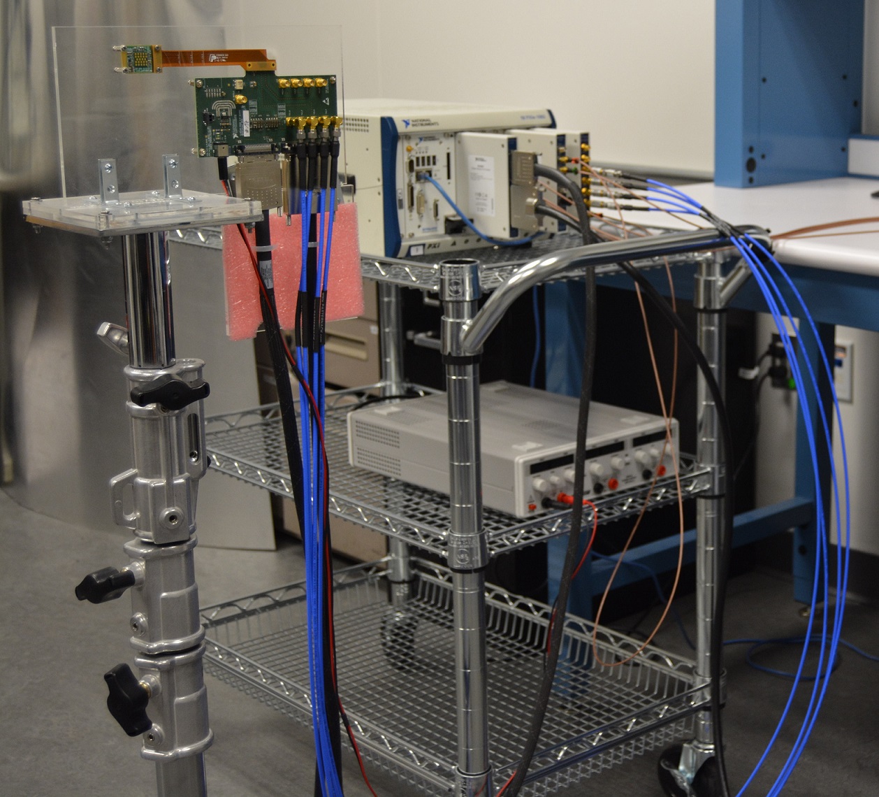
To investigate the effects of mmWave blockage, our earlier work [6] developed a measurement system using two SiBeam 60 GHz phased antenna arrays. The arrays consist of 12 radiating elements with the ability to adjust the phase on each element with 2 bits of precision. Modifying these phases alters the radiation pattern of the array and allows the user to "steer" the antenna array without any moving parts such as a gimbal. A new beamforming vector can be applied in less than one microsecond, which is in sharp contrast to mechanical methods of steering which are typically on the order of tens of milliseconds[24]. The ability to rapidly switch between different steering vectors enables measurements to be conducted over multiple directions on the same timescale as dynamic events such as human blockage.
II-A Hardware Components
To support the SiBeam phased arrays, the measurement system includes two National Instruments (NI) PCI eXtensions for Instumentation Express (PXIe) chassis which perform all baseband processing and necessary communication to maintain synchronization during a measurement. The two chassis are each equipped with several Field Programmable Gate Array (FPGA) modules and Input/Output (I/O) daughterboards that allow the FPGA modules to send baseband and control signals to the arrays as well as share timing signals between the two chassis. A chassis controller running a real-time operating system is also present to send commands to the FPGA modules and to allow the two chassis to communicate via Ethernet. The transmitter (TX) portion of the measurement system is shown in Fig. 1.
II-B Measurement Procedure
Steering the array is accomplished with a codebook of twelve vectors that define the phases of the elements in the array. To begin, the TX will apply one steering vector, and the RX will cycle through its entire codebook of twelve steering vectors. For each of these, the RX will acquire a single power delay profile (PDP) which describes the multipath characteristics of the wireless channel. The TX will then advance to the next steering vector and the RX repeats the same procedure to acquire twelve more PDPs, one for each of the steering vectors in its codebook. When the TX has finished sweeping over its whole codebook, we have in total 144 PDPs that were each acquired for a different combination of TX and RX steering vectors, or pointing angle combination (PAC).
This 144 PAC scan be performed in less than 1 millisecond due to the very rapid steering ability of the phased arrays. Critically, this is fast enough that a human walking at a typical speed will not move very far between scans, and it is therefore possible to observe the time evolution of attenuation due to human blockage across the multiple paths that are present in the channel. Due to memory constraints, the scans can only be repeated for a relatively short period of time. For the results shown in this paper, the scans were repeated over a period of 5.6 seconds, which is more than enough time for a single blockage event to begin and end.
III Blockage Experiments
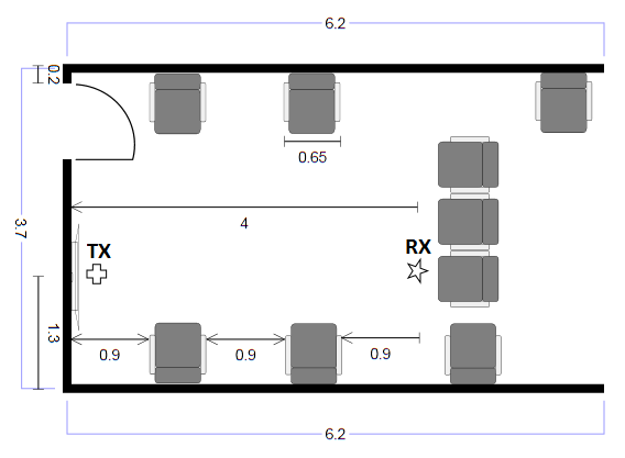
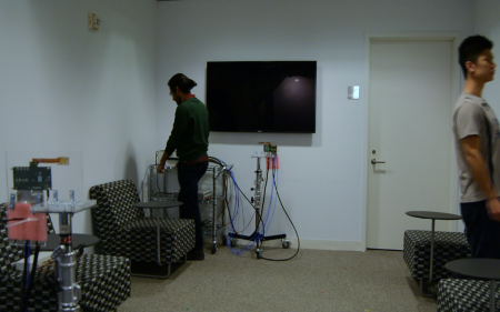
Measurements were performed in a room on the NYU Tandon campus chosen because it emulates a typical living room environment. The TX was placed below a wall-mounted television and the RX was located in front of a sofa 4 meters away from the TX. Both were at a height of 1 meter. Additional furniture in the room included several fabric chairs with attached tables. Fig. 2 shows the dimensions of the room as well as the locations of the TX, RX and furniture.
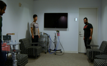
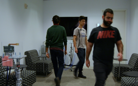
Measurements were performed for a variety of scenarios. The number of human blockers moving throughout the room varied from one to three, with the single blocker experiments performed with different distances between the blocker and the TX/RX. Some measurements were also performed with mobility at the RX in addition to blockage. For this work, we focus our analysis on a single trace from a measurement with three blockers walking through the room simultaneously. Fig. 3 shows still images taken from a video of the blockers as they moved though the room.

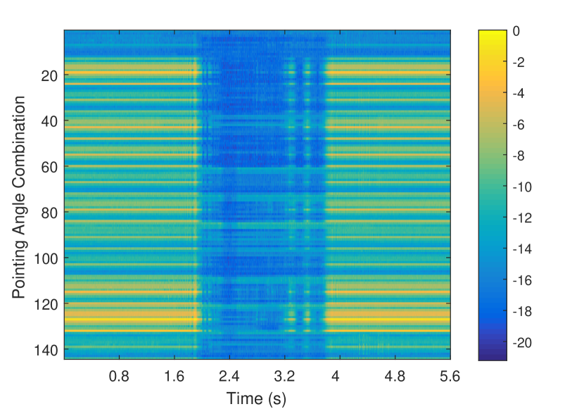
For this particular measurement, Fig. 4 shows the received power over time for all combination of TX and RX steering vectors. Received power is normalized to the strongest value observed when no paths are blocked. There is a very long blockage event visible in this figure, however note that some pointing angle combinations (those which direct some energy to a NLOS path in the channel) are not blocked at the same time as the more dominant LOS path. By incorporating this measurement trace into ns-3, we can explore how different beam tracking schemes are able to exploit this path diversity to overcome the effects of blockage.
IV Modeling the 5G NR Beam Search
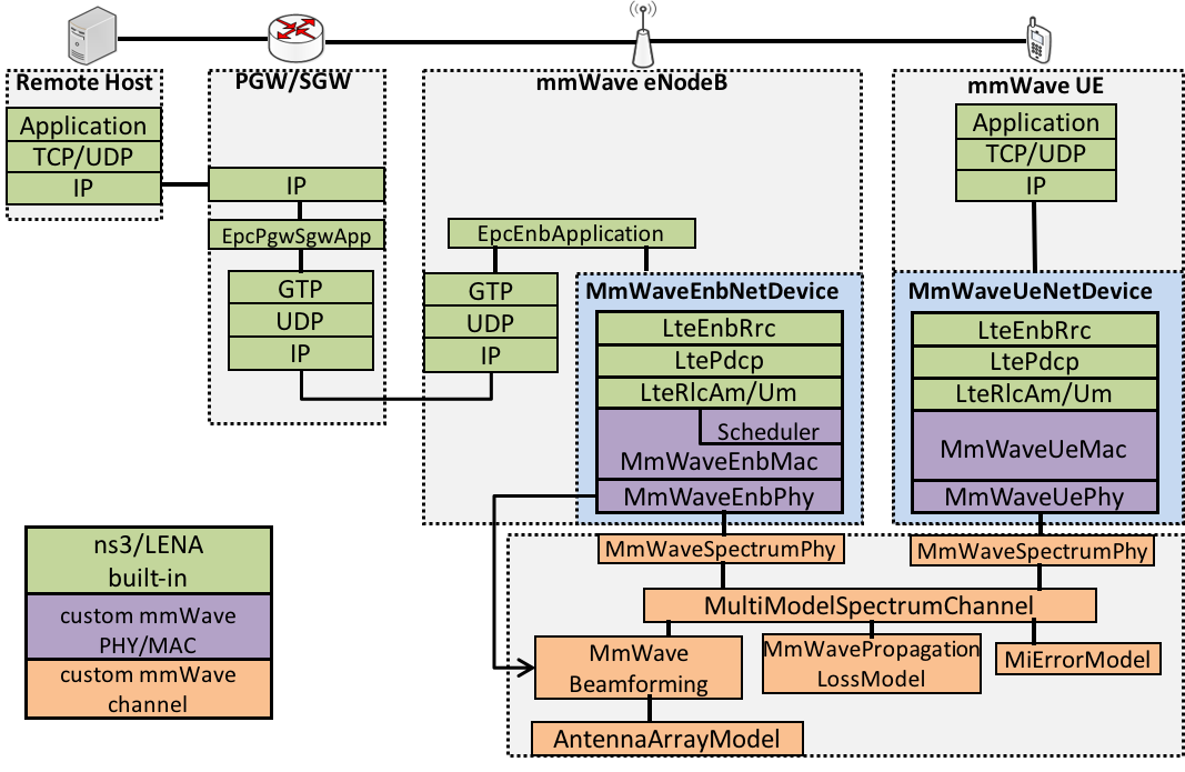
To understand the end-to-end effects of blockage, the measured traces are incorporated into the discrete-event network simulator ns-3 with a mmWave module developed in our earlier work [7, 8], as depicted in Fig. 5. The simulator includes a complete model for all PHY, MAC, RLC and PDCP layers in the RAN, as well as the core networks protocols and delay. In particular, both MAC and RLC retransmissions during transmission losses are accounted for.
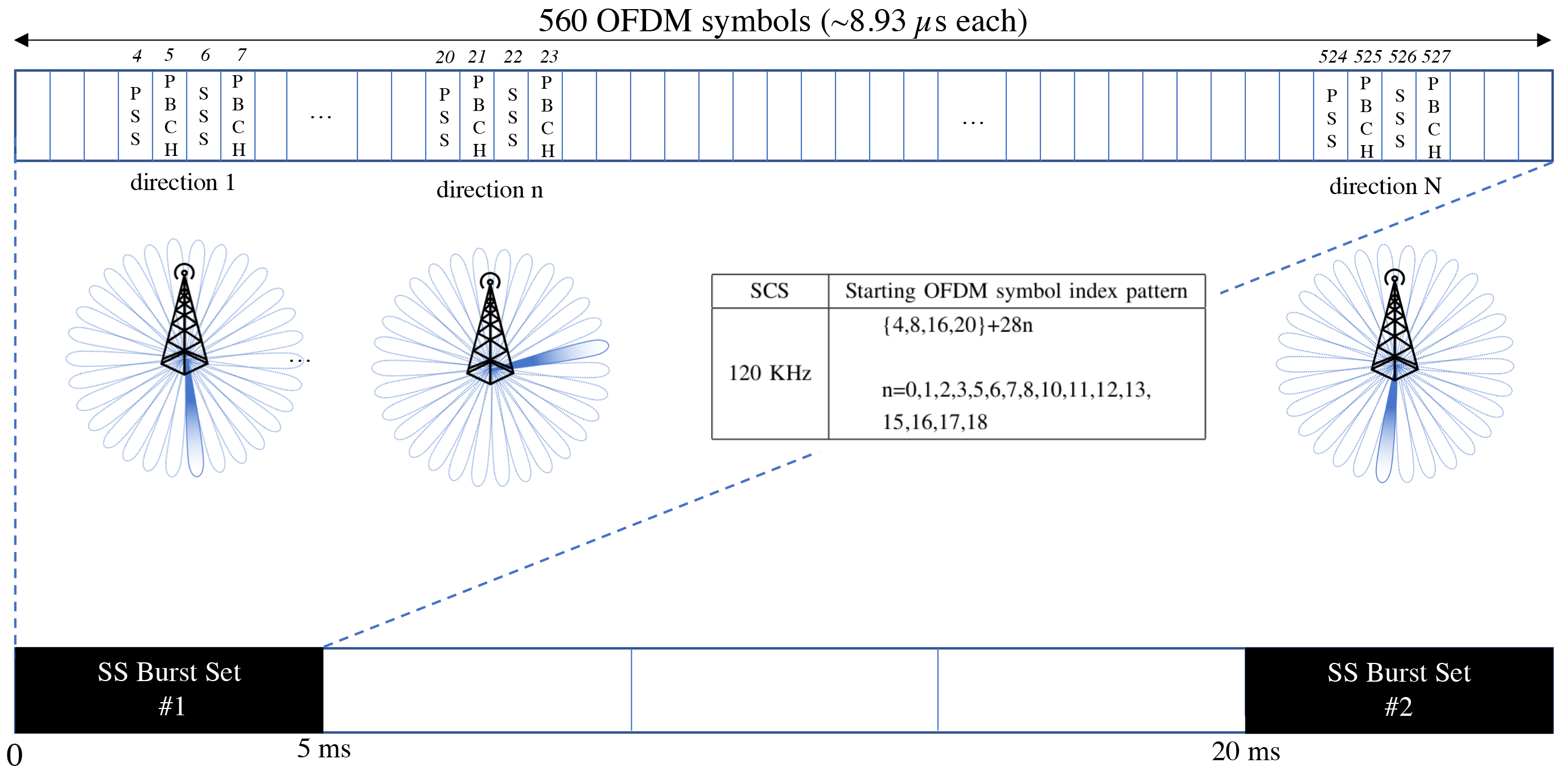
In this work, we have supplemented the model with the NR beam management procedure as described in [1] and shown in Fig. 6. In the NR standard, beam tracking is performed by the gNB cell periodically transmitting a so-called synchronization signal (SS) burst that scans across a set of possible transmit directions. In this study, we assume that both the gNB cell and UE use phased array transceivers identical to those used in the measurements. Hence, each side must scan 12 directions. At the gNB side, we assume a default configuration where the SS burst set is repeated every 20 ms. Within one SS burst set, the gNB cell transmits pilots in all 12 directions over a specific set of OFDM symbols, as indicated in the table of Fig. 6, so that the remaining resources within the 5 ms burst set can be used for data or other control channels.
The speed of the tracking then depends on the UE receiver capabilities. We consider two possible UE beamforming architectures: analog or fully digital. These two transceiver choices were also evaluated in the context of initial access in [22, 23]. The front-end architecture choice remains a major outstanding design issue in mmWave systems as there are significant implications for power and area.
From the perspective of search, the key limitation of analog beamforming is that it can only “look” in one direction at a time. Since we assume in this study that the UE must search 12 possible directions, a full cycle takes ms. The gNB and UE update their beamforming vector pair whenever a stronger received power is detected. In contrast, in digital beamforming, the UE can “look” in all directions simultaneously and thus is able to measure all directions every 20 ms.
V Simulation Results and Discussion
To evaluate the end-to-end performance with blockage, we simulate sending TCP traffic to the UE whose mmWave channel and beam search procedure is described above. We use a 400 MHz bandwidth and full buffer traffic. The RLC buffer size is configured to be 5 MB and the core network round-trip delay is set to 10 ms. The results are shown in Fig. 7 for three different beam tracking schemes:
-
1.
Digital transceiver at the UE: the UE performs digital beamforming, meaning that it will capture the best beam pair at every SS burst set.
-
2.
Analog transceiver at the UE: the UE performs analog beamforming, meaning that it will take a number of SS burst sets before discovering the best beam pair.
-
3.
No tracking: the UE detects the best beam pair in the initial access stage and uses this pair across the entire simulation.
In the SINR plot, we observe three blockage events (at 2s-3s, 3.2s-3.3s and 3.4s-3.6s). The no-tracking line shows that the SINR drops around 14 dB when the link breaks. With digital beamforming, the SINR drops by approximately 9 dB thanks to the ability to track the reflected path. The analog case can also utilize the reflected path, but has a small additional delay in finding the path compared to the digital case.
The rate is almost the same when the primary path is available. However, during blockage events, the digital case achieves a higher and smoother rate, which is consistent with the SINR plot. The analog case is slightly worse, but still produces a much higher rate compared to the no-tracking case.
The RLC buffer size is large enough to prevent overflow, but inevitably there was increased latency during blockage events. For all three beamtracking schemes the Round Trip Time (RTT) has the same behavior when there is no blockage. The trend differs between the three methods when the line-of-sight path is blocked. As expected, fully digital beamforming provides slightly lower latency than analog beamforming, due to a more timely reaction to the blockage event. In contrast, the no-tracking case barely transmitted any data during the blockage event and therefore accumulated more packets in the buffer and experienced the highest latency.
Conclusions
In this paper, we have presented a detailed measurement-based study of end-to-end performance over mmWave links during blockage. The study incorporates real spatial-temporal channel measurements into a thorough simulation. We see that blockage can indeed dramatically impair the end-to-end performance, due to the beam search delays and interactions with TCP. Fully digital beamforming can somewhat reduce the effects of blockage suggesting that power efficient methods for realizing such front-end architectures may be worth investigating.
References
- [1] 3GPP, “NR; Overall description; Stage-2,” TR 38.300, 2017.
- [2] T. S. Rappaport et al., “Millimeter wave mobile communications for 5G cellular: It will work!” IEEE Access, vol. 1, pp. 335–349, May 2013.
- [3] S. Rangan, T. S. Rappaport, and E. Erkip, “Millimeter-wave cellular wireless networks: Potentials and challenges,” Proc. IEEE, vol. 102, no. 3, pp. 366–385, Mar. 2014.
- [4] E. Dahlman et al., “5G wireless access: requirements and realization,” IEEE Communications Magazine, vol. 52, no. 12, pp. 42–47, 2014.
- [5] T. S. Rappaport, R. W. Heath Jr., R. C. Daniels, and J. N. Murdock, Millimeter Wave Wireless Communications. Pearson Education, 2014.
- [6] C. Slezak, A. Dhananjay, and S. Rangan, “60 GHz blockage study using phased arrays,” in Proc. 2017 51st Asilomar Conf. on Signals, Syst., and Computers, Oct 2017, pp. 1655–1659.
- [7] M. Mezzavilla, S. Dutta, M. Zhang, M. R. Akdeniz, and S. Rangan, “5G mmWave module for the ns-3 network simulator,” in Proc. ACM Int. Conf. on Modeling, Anal. and Simulation of Wireless and Mobile Syst. ACM, 2015, pp. 283–290.
- [8] R. Ford, M. Zhang, S. Dutta, M. Mezzavilla, S. Rangan, and M. Zorzi, “A framework for end-to-end evaluation of 5G mmWave cellular networks in ns-3,” in Proc. Workshop on ns-3. ACM, 2016, pp. 85–92.
- [9] C. Gustafson and F. Tufvesson, “Characterization of 60 GHz shadowing by human bodies and simple phantoms,” in Proc. 2012 6th European Conf. on Antennas and Propagation (EuCAP), April 2012, pp. 3084–3088.
- [10] G. R. MacCartney, Jr., S. Deng, S. Sun, and T. S. Rappaport, “Millimeter-wave human blockage at 73 GHz with a simple double knife-edge diffraction model and extension for directional antennas,” Proc. IEEE Vehicular Technology Conference (VTC), 9 2016.
- [11] R. J. Weiler, M. Peter, W. Keusgen, K. Sakaguchi, and F. Undi, “Environment induced shadowing of urban millimeter-wave access links,” IEEE Wireless Communications Letters, vol. 5, no. 4, pp. 440–443, Aug 2016.
- [12] M. Giordani, M. Mezzavilla, A. Dhananjay, S. Rangan, and M. Zorzi, “Channel dynamics and SNR tracking in millimeter wave cellular systems,” in Proc. IEEE European Wireless Conference, May 2016, pp. 1–8.
- [13] M. Jacob, S. Priebe, A. Maltsev, A. Lomayev, V. Erceg, and T. Kürner, “A ray tracing based stochastic human blockage model for the IEEE 802.11ad 60 GHz channel model,” in 2011 5th European Conference on Antennas and Propagation (EuCAP), April 2011, pp. 473–477.
- [14] G. R. MacCartney, T. S. Rappaport, and S. Rangan, “Rapid fading due to human blockage in pedestrian crowds at 5G millimeter-wave frequencies,” in Proc. 2017 IEEE Global Commun. Conf., Dec 2017, pp. 1–7.
- [15] S. Collonge, G. Zaharia, and G. Zein, “Influence of the human activity on wide-band characteristics of the 60 GHz indoor radio channel,” IEEE Wireless Comm., vol. 3, no. 6, pp. 2396 – 2406, nov. 2004.
- [16] M. Peter et al., “Analyzing human body shadowing at 60 GHz: Systematic wideband MIMO measurements and modeling approaches,” in Proc. 2012 6th European Conf. on Antennas and Propagation (EuCAP), April 2012, pp. 468–472.
- [17] V. Raghavan et al., “Statistical blockage modeling and robustness of beamforming in millimeter wave systems,” ArXiv e-prints, Jan. 2018.
- [18] M. Zhang et al., “Transport layer performance in 5G mmWave cellular,” in Proc. 2016 IEEE Conf. Comp. Commun. Workshops (INFOCOM WKSHPS), Apr. 2016, pp. 730–735.
- [19] R. Ford, M. Zhang, M. Mezzavilla, S. Dutta, S. Rangan, and M. Zorzi, “Achieving ultra-low latency in 5G millimeter wave cellular networks,” IEEE Communications Magazine, vol. 55, no. 3, pp. 196–203, March 2017.
- [20] M. Zhang, M. Mezzavilla, J. Zhu, S. Rangan, and S. Panwar, “TCP dynamics over mmWave links,” in Proc. 2017 IEEE 18th Int. Workshop on Signal Process. Advances in Wireless Commun. (SPAWC), July 2017, pp. 1–6.
- [21] S. Dutta, M. Mezzavilla, R. Ford, M. Zhang, S. Rangan, and M. Zorzi, “Frame structure design and analysis for millimeter wave cellular systems,” IEEE Transactions on Wireless Communications, vol. 16, no. 3, pp. 1508–1522, March 2017.
- [22] C. N. Barati et al., “Directional cell discovery in millimeter wave cellular networks,” IEEE Trans. Wireless Commun., vol. 14, no. 12, pp. 6664 – 6678, Nov. 2015.
- [23] ——, “Initial access in millimeter wave cellular systems,” IEEE Transactions on Wireless Communications, vol. 15, no. 12, pp. 7926–7940, 2016.
- [24] PTU - D48 E Series User Manual, 4th ed., FLIR Motion Control Systems, https://www.flir.com/globalassets/imported-assets/document/d48-e-series-user-manual.pdf, Jan. 2011.