September 30, 2017
Development of Energy-Resolved Neutron Imaging Detectors at RADEN
Abstract
Energy-resolved neutron imaging at a pulsed source utilizes the energy-dependent neutron transmission measured via time-of-flight to extract quantitative information about the internal microstructure of an object. At the RADEN instrument at J-PARC in Japan, we use cutting-edge detectors employing micro-pattern detectors or fast Li-glass scintillators and fast, all-digital data acquisition to perform such measurements, while continuing their development toward better utilization of the intense neutron source. In particular, for the Micro-Pixel Chamber based Neutron Imaging Detector (NID), a micro-pattern detector with a 400 m pitch and employing 3He for neutron conversion, we have successfully improved the spatial resolution from 200 to 100 m, increased the detection efficiency from 18 to 26% for thermal neutrons, and increased the maximum count rate from 0.4 to 1 Mcps. We are also testing a new readout element with a 215 m pitch for further improved spatial resolution, and a NID with boron-based neutron converter for increased rate performance.
1 Introduction
The Energy-Resolved Neutron Imaging System, RADEN [1], located at beam line BL22 of the Materials and Life Science Experimental Facility (MLF) at J-PARC in Japan, is designed to take full advantage of the high-intensity, pulsed neutron beam of the MLF to perform not only conventional radiography/tomography, but also more recently developed energy-resolved neutron imaging techniques. These energy-resolved techniques enable observation of the macroscopic distribution of microscopic properties within bulk materials in situ, including crystallographic structure and internal strain (Bragg-edge transmission [2]), nuclide-specific density and temperature distributions (neutron resonance absorption [3]), and internal/external magnetic fields (pulsed, polarized neutron imaging [4]), by analysis of the energy-dependent neutron transmission point-by-point over a sample. Utilizing the low-divergence, pulsed neutron beam at RADEN, we combine advanced, two-dimensional neutron detectors featuring fine time resolution with the determination of neutron energy by the time-of-flight method to allow observation of the energy-dependent transmission simultaneously at all points in a single measurement. The quantitative nature of these techniques and potentially short measurement times make energy-resolved neutron imaging at intense, pulsed neutron sources very attractive for both scientific and industrial applications.
To carry out such measurements in the high-rate, high-background environment at a pulsed spallation neutron source such as the J-PARC MLF requires detectors with sub-s time and sub-mm spatial resolutions, excellent background rejection, and high rate capability. At RADEN, we use cutting-edge detector systems, which have been developed in Japan, employing micro-pattern detectors or fast Li-glass scintillators coupled with high-speed, FPGA (Field Programmable Gate Array)-based data acquisition systems. As opposed to conventional CCD camera detectors, these event-type detectors measure each individual neutron event to provide the necessary time resolution and event-by-event background rejection. Furthermore, the micro-pattern detectors, by virtue of sub-mm strip pitches, are able to operate at Mcps (mega-counts-per-second) rates and provide spatial resolutions on par with conventional CCD camera systems, while the fast decay time of about 100 ns for Li-glass scintillator potentially allows high overall count rates on the order of 100 Mcps.
In this paper, we introduce the event-type neutron imaging detectors in use at RADEN and discuss our ongoing detector development activities, including results of tests carried out at RADEN.
2 Event-Type Detectors at RADEN
The event-type detector systems currently available at RADEN include two micro-pattern detectors, the NID (Micro-pixel chamber based Neutron Imaging Detector) [5, 6] and nGEM (boron-coated Gas Electron Multiplier) [7] developed at Kyoto University and KEK, respectively, along with a pixelated Li-glass scintillator detector, the LiTA12 (6Li Time Analyzer, model 2012) [8] from KEK. The main features of these detectors are listed in Table 1. The micro-pattern detectors have a detection area of cm2 and are based on gaseous time projection chambers with charge amplification provided by a micro-pixel chamber (PIC) [9] in the case of the NID and multiple, thin-foil Gas Electron Multipliers (GEMs) [10] for the nGEM. The NID incorporates 3He in the gas mixture for 26% efficiency at a neutron energy of meV. The nGEM, on the other hand, uses a 1.2-m thick 10B coating (98% purity) deposited on the aluminum drift cathode and both sides of one GEM foil to achieve 10% efficiency at meV. The LiTA12 is comprised of a array of 6Li-impregnated glass scintillator pixels (type GS20) matched to a Hamamatsu H9500 multi-anode photomultiplier with a 3 mm anode pitch and a total area of cm2. The Li-glass scintillator provides a thermal neutron efficiency of more than 48% per pixel at meV, with an overall efficiency of 23% when including dead space between the pixels. All detectors feature fast, all-digital FPGA-based data acquisition with data transfer over Gigabit Ethernet to provide for the necessary time resolution and high-rate operation required at the intense pulsed neutron source of the MLF.
In preliminary testing reported in Refs. [11] and [12], as well as in subsequent testing, the expected spatial resolution of each detector was confirmed at RADEN. The NID and nGEM were evaluated using a Gd test target designed at RADEN [13], while that of the LiTA12 was confirmed using a simple shape made from Cd plate. The rate performance of each system was also studied using adjustable B4C slits to vary the incident neutron intensity. To characterize the rate performance, we determined two quantities: peak count-rate capacity, which indicates the absolute maximum instantaneous neutron rate measured over the whole detector, and effective peak count rate, which indicates the instantaneous peak rate achievable over the whole detector with good linearity in count rate versus incident intensity (where good is defined here as less than 2% event loss). Both of these rates are what are referred to as global instantaneous peak rates [14]. With the strongly-peaked neutron time-of-flight spectrum at the MLF, it is these global instantaneous rates which limit the performance of the detector systems at RADEN. The results of these studies are listed in Table 1.
| Detector | NID | nGEM | LiTA12 |
|---|---|---|---|
| Type | Micro-Pattern | Micro-Pattern | Pixelated Scintillator |
| Neutron converter | 3He | 10B | 6Li |
| Area | cm2 | cm2 | cm2 |
| Time resolution | 0.25 s | 15 ns | 40 ns |
| Spatial resolution | 0.1 mm | 1 mm | 3 mm |
| Efficiency (at meV) | 26% | 10% | 23% |
| Peak count-rate capacity | 8 Mcps | 4.6 Mcps | 8 Mcps |
| Effective peak count rate | 1 Mcps | 180 kcps | 6 Mcps |
We are also actively developing the LiTA12 and NID at RADEN in order to optimize their characteristics, including spatial resolution, rate performance, and detection efficiency, for energy-resolved neutron imaging. (While the nGEM is extensively used at RADEN, it is not currently being developed by our group.) Specifically, the LiTA12 is being optimized for neutron resonance absorption measurements by replacing the scintillator pixels with a single, flat scintillator with increased thickness in order to increase detection efficiency for epithermal neutrons (i.e., those in the resonance energy region above eV) [15]. The single scintillator also allows calculation of the centroid of multiple anodes for an improvement in spatial resolution to less than 1 mm [15, 13]. Additionally, for the NID, we have upgraded the data acquisition hardware and optimized the gas mixture for improved spatial resolution and rate performance [12], with further development underway. For the remainder of this paper, we will discuss ongoing development of the NID in detail.
3 Development of the NID at RADEN
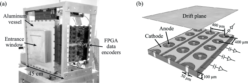
The NID, shown in Fig. 1(a), uses a time projection chamber with a drift length of 2.5 cm and a 10 cm 10 cm readout plane consisting of a micro-pixel chamber (PIC), coupled to a modular, FPGA-based data acquisition system [16]. The PIC is a micro-pattern detector with a 400 m pitch, two-dimensional strip readout, which through its unique microstructure, illustrated in Fig. 1(b), achieves both charge amplification and analog strip readout. To facilitate neutron detection, a CF4–iC4H10–3He gas mixture (mixing ratio 45:5:50) at 2 atm total pressure is used, providing a detection efficiency of 26% at meV (on par with conventional CCD camera systems). In this gas mixture, the tracks of the reaction products are less than 5 mm. A drift field of 1,600 V/cm is used (50 m/ns drift velocity, 0.5 s maximum drift time), and the PIC readout is operated at an anode voltage around 650 V for a gain factor of 100 to 150. Following a neutron-3He interaction, the three-dimensional track and energy deposition (estimated via time-over-threshold) of the resultant proton-triton pair are recorded in the FPGA-based data encoder modules and sent to PC via Gigabit Ethernet. This detailed tracking information allows the NID to achieve a fine spatial resolution of 0.1 mm and a low gamma sensitivity of less than 10-12. The NID also features a time resolution of 0.25 s, a peak count-rate capacity of 8 Mcps, and an effective peak count rate of 1 Mcps.
In our initial development described in Ref. [12], we performed an upgrade of the data acquisition hardware and replaced the original Ar–C2H6–3He (63:7:30 at 2 atm) gas mixture [5] with the current CF4-based mixture. For the hardware, the data output port of the FPGA-based data encoder modules was upgraded from 100BASE-T to Gigabit Ethernet, improving the throughput of the data acquisition hardware by roughly a factor of nine. The CF4-based gas mixture provided a more than two times faster drift velocity for shorter charge evacuation times, nearly two times the stopping power for reduced event sizes, and a more than three-fold reduction in the electron diffusion for improved event localization as compared to the Ar-based mixture. Furthermore, the higher stopping power of CF4 allowed us to increase the 3He fraction while maintaining smaller event sizes. Taken together, these detector improvements provided an increase in the peak count-rate capacity from 0.6 to 8 Mcps and an increase in the detection efficiency from 18% to the current 26%. The updated encoder modules and new gas mixture have been thoroughly tested at RADEN and are now part of the standard setup for our NID system. Ongoing development efforts to improve the spatial resolution and rate performance are described below, including optimization of data analysis algorithms, development of a new PIC readout plane with reduced pitch, and testing of a NID with 10B-based neutron converter.
3.1 Optimization of data analysis algorithms
The digital data produced by the NID consists of a stream of hits comprised of strip number, hit time, and a flag indicating whether the analog signal was rising or falling when it crossed the discriminator threshold. It is the job of the offline data analysis to match rising and falling hits and calculate the time-over-threshold, group individual hits into neutron events (referred to as clustering), and determine the precise neutron interaction point (referred to as position reconstruction). By optimizing the clustering and position reconstruction algorithms, we have recently been able to improve the effective peak count rate and maximize the spatial resolution of the NID.
3.1.1 Clustering algorithm
After the hardware upgrade of Ref. [12], the NID achieved a peak count-rate capacity of 8 Mcps with good linearity up to this maximum when considering only raw hits. The lower effective peak count rate arises mostly from the clustering of the offline analysis. The original clustering algorithm was based on a simple, single-linkage clustering with hits grouped solely by the distance between them (i.e., all hits whose inter-hit separation was within a specified cut-off were considered to come from the same event). While this simple algorithm worked well at low neutron rates, event pile-up was seen to become significant at global peak rates above 400 kcps. This is illustrated in Fig. 2(a), where the neutron reconstruction efficiency, defined as the ratio of reconstructed neutron events to the expected number of neutron events (as derived from the number of raw hits), is plotted as a function of neutron time-of-flight (TOF) for global peak rates up to 5.6 Mcps. The clear dip at the peak of the TOF distribution, shown by the dashed line in Fig. 2(a), indicates event loss due to pile-up, which increases with the peak rate. The observed event loss is about 2% at a global peak rate of 400 kcps.
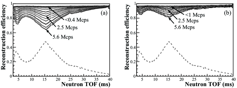
To address this poor performance, we are now developing a new algorithm employing density-based clustering (based on DBSCAN [17]), followed by explicit event pile-up resolution. For our initial study, clusters that overlap in time were grouped, and a mismatch in the number of clusters on each of the perpendicular strip planes was taken as a signal of event pile-up. Then, in the case that the number of clusters differs by one, the largest cluster was assumed to be a pile-up event and was allowed to pair with two clusters from the opposite strip orientation. Even with this simple method, the improvement in the neutron reconstruction efficiency is clearly visible in Fig. 2(b), where event loss was reduced to 2% at 1 Mcps global peak rate. The neutron reconstruction efficiency is expected to improve further as we increase the sophistication of the event pile-up resolution algorithm. We will also study the effect of the new clustering algorithm on the spatial resolution.
3.1.2 Position reconstruction algorithm
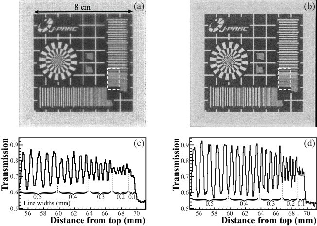
In the offline analysis, neutron position is determined event-by-event via a fit to the time-over-threshold (TOT) distributions for each strip orientation, as described in Ref. [6]. The fits are carried out using template distributions generated with a GEANT4 [18, 19] simulation of the NID system, where the templates are indexed by the proton-triton track unit vector. This fitting procedure allows the clean separation of the proton and triton (with 5% observable contamination from misidentified events), facilitating the fine spatial resolution achieved by this detector. In the original template selection algorithm, the unit vector was determined from the fully reconstructed three-dimensional track, requiring input of three adjustable parameters (i.e., x, y, and z offsets) and several calculation steps. We have recently developed a simplified template selection algorithm that uses the track projections, which are measured directly, and one adjustable parameter, namely, the average proton-triton track length. Images of the Gd test target taken at RADEN are shown in Fig. 3(a) and 3(b), reconstructed from the same data using the original and simplified template selection algorithms, respectively. Also, projections of the line pairs within the dashed regions in Figs. 3(a) and 3(b) are shown in Figs. 3(c) and 3(d), respectively. From Figs. 3(c) and 3(d), the spatial resolution was evaluated as 200 and 100 m, respectively, at a Modulation Transfer Function (MTF) value of 10%. These results show clearly that the simplified template selection algorithm provides both improved spatial resolution and image uniformity, indicating better matching of templates to the measured TOT distributions.
3.2 PIC with reduced strip pitch
To provide a significant improvement in the spatial resolution, we are working with the manufacturer of the PIC, DaiNippon Printing Co., Ltd., to develop a new PIC readout element with reduced strip pitch. (Simulations indicate that the spatial resolution should scale roughly with the strip pitch.) The standard PIC described above is manufactured using conventional printed circuit board techniques, which, due to poor tolerances, are not well suited to producing very fine structures below several 10s m. By changing to a MEMS (Micro-Electro-Mechanical Systems)-based process, however, smaller structures (as small as 10 m) can be created with very good uniformity. Using MEMS manufacturing techniques, a new PIC readout element, referred to as a TSV (Through-Silicon-Via) PIC, with a 215 m pitch, or nearly half that of the standard, 400-m pitch PIC, has been successfully produced. For our initial study, a 215 m pitch test piece, comprised of strips for a detection area of cm2, was manufactured and testing was carried out at RADEN. In preliminary testing described in Ref. [12], the TSV PIC test piece provided sufficient gain for neutron detection (at about 200), but showed poor gain stability under sustained neutron irradiation. This observed gain instability was thought to arise from charge build-up within the silicon substrate, which in the MEMS process is used in place of the insulating polyimide substrate of the standard PIC.
Based on the above assumption, we investigated the effect of electrically grounding the silicon substrate, which would be expected to allow the evacuation of any charge build-up, in a subsequent test of the TSV PIC. Figure 4(a) shows the relative gain measured over a 5-hour period of constant neutron irradiation with and without grounding the substrate, where the gain is represented by the peak TOT value averaged over all channels. These results show that by grounding the substrate, the gain stability of the TSV PIC can be significantly improved. With the gain stabilized, we were then able to take the first test image with the fine-pitch PIC as shown in Fig. 4(b). The statistics are low, but the Siemens star of our Gd test target is clearly visible. We are now preparing a new 215 m pitch test piece with strips and an area of 5.5 cm 5.5 cm, and we will continue to study the gain stability and spatial resolution with this large-area TSV PIC from this spring at RADEN.

3.3 NID with boron-based neutron converter
To provide a significant improvement in the peak count-rate capacity, we are also developing a NID with a 10B-based neutron converter. Use of a boron-based converter is expected to provide a three-fold increase in the peak count-rate capacity of the system (to over 20 Mcps) due to the fact that the alpha particle released in the neutron-10B reaction travels a much shorter distance in the gas of the detector as compared to the lighter proton and triton in the 3He case, thereby creating fewer hits per event and allowing more events to be transmitted over the same system bandwidth. This small event size (of only 2 or 3 hit strips per readout direction), however, comes with a trade-off in spatial resolution as the limited information renders detailed reconstruction algorithms, such as the template-fitting method above and the TPC method of Ref. [20], less effective. The change from 3He gas to a 10B-based converter also reduces the long-term maintenance costs of the detector.
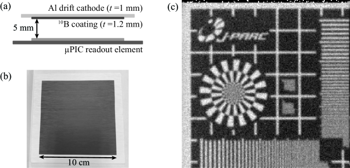
As a proof-of-principle demonstration, we installed an aluminum drift cathode with a 1.2-m thick 10B coating (98% purity) into one of our NID systems, as shown in Figs. 5(a) and 5(b), and filled the vessel with a CF4-iC4H10 (90:10) gas mixture at 1.6 atm. The CF4-based gas mixture was chosen for its high stopping power to keep the alpha tracks short. Figure 5(c) is an image of the Gd test target produced at RADEN, showing a spatial resolution of around 500 m, or slightly larger than the pitch of the PIC strip readout. We also observed a 2.8 times reduction in event size compared to the 3He case, confirming, in principle, an expected increase in peak count-rate capacity of up to 22 Mcps. Due to the low efficiency of only 3 to 5% at meV for the present converter and a limited neutron beam power of 150 kW at the time of the measurement, however, we were unable to directly measure the peak count-rate capacity. We are now considering new converter designs for increased efficiency, and we will measure the peak count-rate capacity in a future test at the MLF.
4 Conclusion
At the RADEN instrument of the J-PARC MLF, we use advanced event-type neutron imaging detectors, including the NID and nGEM micro-pattern detectors and the LiTA12 scintillator pixel detector. The performance of these detectors has been verified at RADEN, and they have been used by both the RADEN instrument group and general users to carry out energy-resolved neutron imaging measurements since 2015. In order to fully utilize the intense pulsed neutron beam of the MLF and better meet the needs of users, we continue to develop these detectors for improved spatial resolution, higher efficiency, and better rate performance. Specifically, through the ongoing development of the NID system described here, we have improved the spatial resolution from 200 to 100 m at 10% MTF, increased the efficiency from 18 to 26% at meV, and increased the effective peak count rate from 0.4 to 1 Mcps, with further improvement expected with optimization of the offline event analysis. Furthermore, a new 215 m pitch PIC is expected (from simulation) to provide nearly double the spatial resolution, while a NID with boron converter should provide a factor of three increase in peak count-rate capacity for more than 20 Mcps total throughput.
Acknowledgment
The development of the 215 m pitch TSV PIC readout element and the NID with boron converter was partially supported by JST ERATO Grant No. JPMJER1403, Japan. Testing at RADEN was carried out under MLF Instrument Group Use Proposal No. 2017I0022, MLF General Use Proposal No. 2016B0161, and CROSS Development Use Proposal No. 2017C0004.
References
- [1] T. Shinohara et al., J. Phys.: Conf. Series 746, 012007 (2016).
- [2] H. Sato, O. Takada, K. Iwase, T. Kamiyama, and Y. Kiyanagi, J. Phys.: Conf. Series 251, 012070 (2010).
- [3] H. Sato, T. Kamiyama, and Y. Kiyanagi, Nucl. Instr. and Meth. A 605, 36 (2009).
- [4] T. Shinohara et al., Nucl. Instr. and Meth. A 651, 121 (2011).
- [5] J.D. Parker et al., Nucl. Instr. and Meth. A 697, 23 (2013).
- [6] J.D. Parker et al., Nucl. Instr. and Meth. A 726, 155 (2013).
- [7] S. Uno, T. Uchida, M. Sekimoto, T. Murakami, K. Miyama, M. Shoji, E. Nakano, and T. Koike, Phys. Proc. 37, 600 (2012).
- [8] S. Satoh, JPS Conf. Proc. 8, 051001 (2015).
- [9] A. Ochi, T. Nagayoshi, S. Koishi, T. Tanimori, T. Nagae, and M. Nakamura, Nucl. Instr. and Meth. A 471, 264 (2001).
- [10] F. Sauli, Nucl. Instr. and Meth. A 386, 531 (1997).
- [11] J.D. Parker et al., 2015 IEEE Nuclear Science Symposium and Medical Imaging Conference (NSS/MIC), 1 (2016).
- [12] J.D. Parker et al., 2016 IEEE Nuclear Science Symposium, Medical Imaging Conference and Room-Temperature Semiconductor Detector Workshop (NSS/MIC/RTSD), 1 (2017).
- [13] M. Segawa et al., submitted to these proceedings.
- [14] I. Stefanescu et al., J. Instrumentation 12, P01019 (2017).
- [15] T. Kai et al., Phys. B, in press.
- [16] T. Mizumoto et al., Nucl. Instr. and Meth. A 800, 40 (2015).
- [17] M. Ester, H-P. Kriegel, J. Sander, and X. Xu, Proc. 2nd Int. Conf. Knowledge Discovery and Data Mining (KDD-96), Portland, USA, 1996, p. 226.
- [18] S. Agnostinelli et al., Nucl. Instr. and Meth. A 506, 250 (2003).
- [19] J. Allison et al., IEEE Trans. Nucl. Sci. NS-53, 270 (2006).
- [20] D. Pfeiffer et al., J. Instrumentation 10, P04004 (2015).