Also at] An-Najah National University, Nablus, Palestine
Horizontal Emittance Reduction on a Synchrotron Radiation Light Source with a Robinson Wiggler
Abstract
The performance of synchrotron light facilities are strongly influenced by the photon beam brightness, that can be further increased by reducing the beam emittance. A Robinson Wiggler can be installed in a non-zero dispersion straight section to reduce the horizontal beam emittance. It is composed of an array of magnets of alternated polarities, whose both magnetic field and gradient are of opposite signs. It provides a compact solution to reduce by 50 the horizontal emittance. However, it increases the energy spread by 40. The concept of the Robinson Wiggler (RW) is described here, the first experimental observation of the Robinson effect in a synchrotron light source on the transverse and longitudinal beam properties by the means of four existing undulators is presented and the impact on the photon flux density is studied.
pacs:
Valid PACS appear hereINTRODUCTION
High brightness light sources have allowed for the development or the improvement of new techniques Lengeler (2001); Huang et al. (2013), e.g. coherent X-ray diffraction imaging Miao et al. (1999) and holography Kondratenko and Skrinsky (1977). The brightness is the phase-space density of the photon flux (number of photons emitted per second per bandwidth), evaluated in the forward direction and at the center of the source Kim (1987): , with and the horizontal and vertical angles, and the horizontal and vertical coordinates respectively. Assuming Gaussian photon distribution, and neglecting the variation of the electron transverse position due to the oscillations through the insertion device, the brightness can be written as Krinsky (1983):
with () the size and (the divergence) of the photon beam resulting from the convolution of the electron beam size (divergence) with the photon emission of a single electron. The beam size and divergence can be expressed as: and , where the photon beam divergence resulting from single electron emission through an insertion device, the photon beam size Tanaka and Kitamura (2009), the wavelength of the emitted radiation and is the length of the device.
In a non-zero dispersion straight section for a Gaussian electron beam distribution, the total horizontal beam size and divergence include contributions from both the betatron and the energy spread :
| (1) | |||
with the horizontal emittance, the horizontal betatron amplitude function, and the horizontal dispersion function and its derivative respectively. In the vertical plane, if the vertical dispersion function and its derivative are zero, the vertical beam size and divergence are expressed as:
| (2) | |||
with the vertical emittance and the vertical betatron amplitude function.
At a given wavelength , the emittance of the photon beam at the diffraction limit is defined by :
To reach the diffraction limit, the electron beam emittance should satisfy the condition: . For an operation at Angstrom, an electron beam emittance of lower than pm.rad in both planes is required. Besides, the orientation of the phase space ellipse of the electron beam should match that of the photon beam emitted by a single electron.
In third generation synchrotron light sources the electron beam emittance (e.g. nm.rad at SOLEIL Nadji et al. (2011), nm.rad at Diamond Bartolini (2007)), leads to partial transverse coherence in the X-ray range. Recently, diffraction limited storage rings have appeared Borland (2013); Hettel (2014). Indeed, different approaches are implemented to further reduce the emittance of existing light sources.
The natural horizontal emittance at equilibrium between quantum excitation and radiation damping for an isomagnetic lattice is Lee (2004); Wiedemann (1988):
| (3) |
with is the radius of curvature and is the dispersion invariant given by Wiedemann (1988):
where , and are Twiss parameters Courant and Snyder (1958). The natural horizontal emittance for an isomagnetic lattice can be rewritten in the simplified form as Bengtsson (2008):
| (4) |
where is a constant that depends on the lattice design, is the number of identical dipoles in the storage ring.
A first approach for reducing the horizontal emittance is given by increasing the number of dipoles in the storage ring, moving from Double Bend Achromat lattice (DBA) Berz et al. (2015) (two dipole magnets with focusing quadrupoles between them to form an achromatic cell) and Triple Bend Achromat (TBA) Berz et al. (2015) (combination of a DBA with a dipole at the center) to Multiple Bend Achromat (MBA) lattice Einfeld et al. (1995). Among others, there are several examples: MAX IV operating with 7-BA lattice and transverse gradient in the dipoles produces a beam with horizontal emittance of pm.rad Leemann et al. (2009); Tavares et al. (2014); Eriksson et al. (2016), the project of SPring-8 upgrade, first based on a 10-BA Tsumaki and Kumagai (2006) and later on a 5-BA Tanaka et al. (2016) to achieve a horizontal emittance of pm.rad, the ESRF upgrade proposing a new design based on 7-BA lattice to reach a horizontal emittance of pm.rad Biasci et al. (2014); Raimondi (2016), etc. After the shutdown of the Tevatron collider, it is proposed to use its large tunnel ( km circumference) to house a storage ring of a new light source called the Tevatron-Sized Ultimate Storage Ring (TeVUSR) Borland (2012), that thanks to this large circumference, expects a horizontal emittance of pm.rad using a 7-BA lattice.
A second approach for horizontal emittance reduction consists in increasing the damping rate by installing damping wigglers in zero dispersion straight sections Wiedemann (1988) to enhance the radiation damping by contributing to the synchrotron integrals. One can introduce the ratio where is the second synchrotron integral without the wiggler and is the additive term due to the wiggler Emma and Raubenhemier (2001). The total horizontal emittance with the damping wiggler can be written as:
| (5) |
where and are the emittance and the damping partition number produced in the absence of wiggler, respectively. is the emittance generated by the wiggler in the limit of . The required wiggler length for an isomagnetic lattice is given by:
| (6) |
with the machine circumference, the magnetic rigidity, the classical electron radius, the speed of light in vacuum, the damping time, the relativistic factor, the wiggler field. Different light sources adopted this solution among which PETRA III Tischer et al. (2005) that reached a horizontal emittance of nm.rad by installing m long damping wigglers, PEP-X that replaced the PEP-II tunnel and reached a horizontal emittance of nm.rad by installing m of damping wigglers Wiedemann (1988), NSLS II at Brookhaven National Laboratory installed m of damping wigglers in order to achieve nm.rad horizontal emittance Guo et al. (2009).
The two strategies, i.e. adding damping wigglers and increasing the number of dipoles to low emittance lattices, can also be combined. In this respect, an ”ultimate” PEP-X lattice has been proposed based on 7-BA lattice together with a 90 m damping wigglers in one of the straight sections to reduce the horizontal emittance to pm.rad Nosochkov et al. (2011) at zero current. However, the drawbacks of the damping wigglers solution is the requirement of long insertion devices and the energy consumption of the RF system.
A third approach to reduce the horizontal emittance is given by adjusting the damping partition number by installing in a non-zero dispersion straight section a Robinson wiggler (RW) Robinson (1958), i.e. a magnetic system of high field transverse gradient superimposed to its main alternated pole wiggler field. It consists in installing a magnetic system producing a periodic vertical magnetic field and transverse field gradient . It is enough to install this wiggler in non-zero dispersion straight section without any need to modify the existing infrastructure. First observations have been carried out with success at Cambridge Electron Accelerator Hofmann (1967), and in the PS at CERN Baconnier et al. (1985) showing horizontal emittance reduction. RW has been recently adopted by other light sources to reduce the horizontal emittance like Heifei Light Source Li et al. (2013), Shanghai Synchrotron Radiation Facility Tian et al. (2017) and the Metrology Light Source that benefited from RW to improve Touschek lifetime by lengthening the bunch Goetsch et al. (2014); Tydecks (2016).
In this paper, we show that the Robinson wiggler approach applied to the case of the SOLEIL storage ring enables the reduction of the horizontal emittance, while increasing the energy spread. The experiment has been performed using four U20 undulators as a RW-like by creating off-axis displacement of the electron beam horizontally and simultaneously in the four undulators for getting the required field gradient product. Effects on the radiation are also derived.
I Theoretical approach: horizontal emittance reduction by damping partition number adjustment
I.1 Transverse and longitudinal properties
Over one turn in the storage ring, the electron loses energy by emitting radiation, and gains energy from the RF system. Assuming a sinusoidal RF voltage, the electron motion behaves as a damped harmonic oscillator Lee (2004). The damping process is characterized by the so-called damping partition that determines the damping rate of the emitted radiation. Considering a storage ring of equilibrium horizontal emittance , the variation of the horizontal emittance due to the modification of the damping partition at equilibrium between quantum excitation and radiation damping can be expressed as Abualrob et al. (2012):
| (7) |
The damping partition numbers , , , characterizing the damping rate, are defined as Lee (2004):
According to Robinson theorem Robinson (1958), the total sum of damping partition numbers i.e. of the amount of damping decrement over all degrees of freedom is constant: . In terms of the synchrotron integrals and , is expressed as Lee (2004), where and are given by:
where is the normalized focusing strength in the dipole. It is given in terms of the dipole field and its transverse variation (usually known as the field gradient) as .
At equilibrium between quantum excitation and radiation damping, the relative energy spread for an isomagnetic lattice is Lee (2004):
| (8) |
The variation of the energy spread as a function of can be written as follows Abualrob et al. (2012):
| (9) |
According to equations 7 and 9, the horizontal emittance and the relative energy spread can be modified by varying the horizontal and the longitudinal damping partition numbers and respectively; i.e. by varying the damping partition . The damping partition for a given lattice is determined by its design. It is given in terms of the magnetic field and the field gradient by:
| (10) |
For an isomagnetic storage ring with identical bending magnets, and equipped with separate function magnets (i.e. bending magnets for deflection and quadrupoles for focusing) such as SOLEIL, the damping partition is given by:
where is the radius of the storage ring and is the momentum compaction factor. For the case of SOLEIL (, m, m), the damping partition .
If can be reduced from its usual value to , the horizontal emittance can be divided by (see equation 7), while the energy spread will be increased by (see equation 9).
The bunch length represents the longitudinal distribution of the electron in the phase space and is related to energy spread. In the zero current regime, the bunch length is given by Sands (1971):
| (11) |
where is the synchrotron frequency expressed in terms of the radio-frequency voltage , the momentum compaction factor , the harmonic number , the electron energy , and the revolution frequency as:
| (12) |
I.2 Requirements in terms of magnetic field
For an isomagnetic lattice, the damping partition given by equation 10 can be reduced to:
| (13) |
The damping partition can be significantly modified by installing an insertion device of high vertical field and high field gradient in a non-zero dispersion straight section. A RW of length and peak field contributes to the modification of if inserted in a straight section whose average dispersion function over the length of the wiggler is . The damping partition can get a negative value if according to equation 13.
The SOLEIL storage ring hosts three types of straight sections, as presented in Table 1, all providing non-zero dispersion. could be reduced from to by installing a wiggler of in a short straight section ( m), leading to a reduction of the horizontal emittance from its present value of nm.rad to nm.rad. Inversely, the energy spread will be increased from the present value of to .
| Straight section | Length (m) | (m) | (m) | (m) |
| Long | 412 | 0.206 | 5.58 | 8.03 |
| Medium | 127 | 0.165 | 4.6 | 2.24 |
| Short | 83.6 | 0.252 | 14.38 | 2.36 |
II Experimental observation of the Robinson effect at SOLEIL
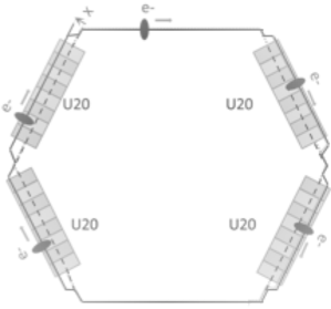
To bring out the effect of a RW on the emittance and the relative energy spread at SOLEIL, different experiments have been performed using four already existing in-vacuum undulators (four U20s) Benabderrahmane et al. (2007); Couprie et al. (2010) in the storage ring. The four U20s are all installed in dispersive short straight sections and generate periodic vertical magnetic field and significant off-axis field gradient. To maximize the total effect, the four U20s were used simultaneously. Figure 1 shows the schematic experimental setup. The electron beam is displaced off-axis in the four undulators by applying simultaneous horizontal bumps using horizontal dipolar correctors at the entrance and at the exit of each undulator. At the entrance the electron beam is displaced horizontally parallel to its initial trajectory and comes back to the initial one at the exit of the undulator. After each horizontal simultaneous bump, the tunes are set back to the nominal values using two quadrupole families. Horizontal beam size and bunch length are measured at each bump with the four U20s open at maximum gap (bare machine) and with the four undulators closed at minimum gap of 5.5 mm.
To study the Robinson effect, the horizontal beam size and the bunch length are measured at 18 mA current distributed in 416 bunches. The low current per bunch enables operation of the machine close to the zero current regime so as to satisfy equation 11.
II.1 The U20: a RW-like undulator
Figure 2 illustrates the peak field variation over the horizontal range mm for a U20 undulator calculated with RADIA code Elleaume et al. (1997); Chubar et al. (1998) for the parameters given in Table 2.

The magnetic field of a U20 is constant over mm in the vicinity of the central on-axis position. Beyond mm, the peak field drops sharply creating a strong magnetic field gradient. The superimposition of the strong magnetic field to the strong field gradient as in a RW can be achieved by creating off-axis propagation of the electron beam through the U20. Consequently, a U20 undulator is a good candidate to study Robinson effect thanks to the particular transverse variation of its magnetic field over wide horizontal range.
| Characteristic | Value | Unit |
| Type | in-vacuum | - |
| Magnet material | - | |
| Magnet dimensions (s, x, z) | 7.5, 50, 30 | mm |
| Magnet chamfer size | 44 | mm |
| Magnetization | 1.05 | T |
| Pole material | Vanadium Permendur | - |
| Pole dimensions (s, x, z) | 2.5, 33, 22 | mm |
| Pole saturation field | 2.35 | T |
| Pole chamfer size | 44 | mm |
| Peak field | 0.97 | T |
| Period length | 20 | mm |
| (Magnetic) minimum gap height | 5.5 | mm |
| Period number | 98 | - |
| Deflection parameter | 1.8 | - |
Figure 3 illustrates the magnetic field multiplied by the field gradient integrated over the undulator length for the four U20 undulators versus transverse position. The zone of interest for the observation of the Robinson effect is that of maximum magnetic field and maximum field gradient. The four U20 undulators show a significant peak of at mm.

II.2 Machine tuning for off-axis propagation

In the case of the SOLEIL storage ring, the optical functions vary significantly when horizontal bumps reach large values, since the horizontal bump creates off-axis propagation in a large number of sextupoles leading to additional focusing. The optical functions corresponding to each bump are simulated with the Accelerator Toolbox (AT) code Terebilo (2001) at the location of the photon beam profile sensor as a function of the horizontal beam position at any given horizontal position in the four U20s and any longitudinal position in the storage ring. . Figure 4 shows the AT simulation of the optical functions and , assuming a simultaneous horizontal bump in the four U20 undulators.
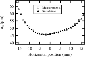


Figure 5 shows the horizontal beam size measured with a pinhole camera as a function of the horizontal position for a bare machine and the beam size obtained by simulation. Good agreement between measurements and AT results confirms the good quality of the model used in AT code.
Figure 6 shows the damping partition as a function of the horizontal position in the four U20s (undulators are closed at gap mm) calculated with equation 13. The dissymetry is due to the fact that differs for positive and negative values of the horizontal position. The damping partition can even evaluate to negative values and reaches a minimum of , whereas a damping partition of is required to reduce the horizontal emittance by factor of 2 (see equation 7). It is not possible to get the value of , since some beam instability appears at larger bumps leading to horizontal emittance reduction by a factor of 0.45 and energy spread increase by a factor of 1.3.
The variation of the natural horizontal emittance with the bump is also taken into account. Figure 7 (a) shows the natural horizontal beam emittance as a function of the horizontal beam position obtained with AT simulation (U20s are open). It is modified due to the horizontal beam displacement, asymmetric increase is noticed around the nominal propagation axis. Figure 7 (b) shows the calculated horizontal beam emittance with equation 7 in the case of four U20s closed at minimum gap, with the natural horizontal beam emittance deduced from Fig. 7 (a) and the damping partition of Fig. 6.
II.3 Measurement of Robinson effect on the longitudinal beam properties
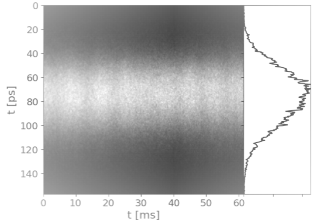
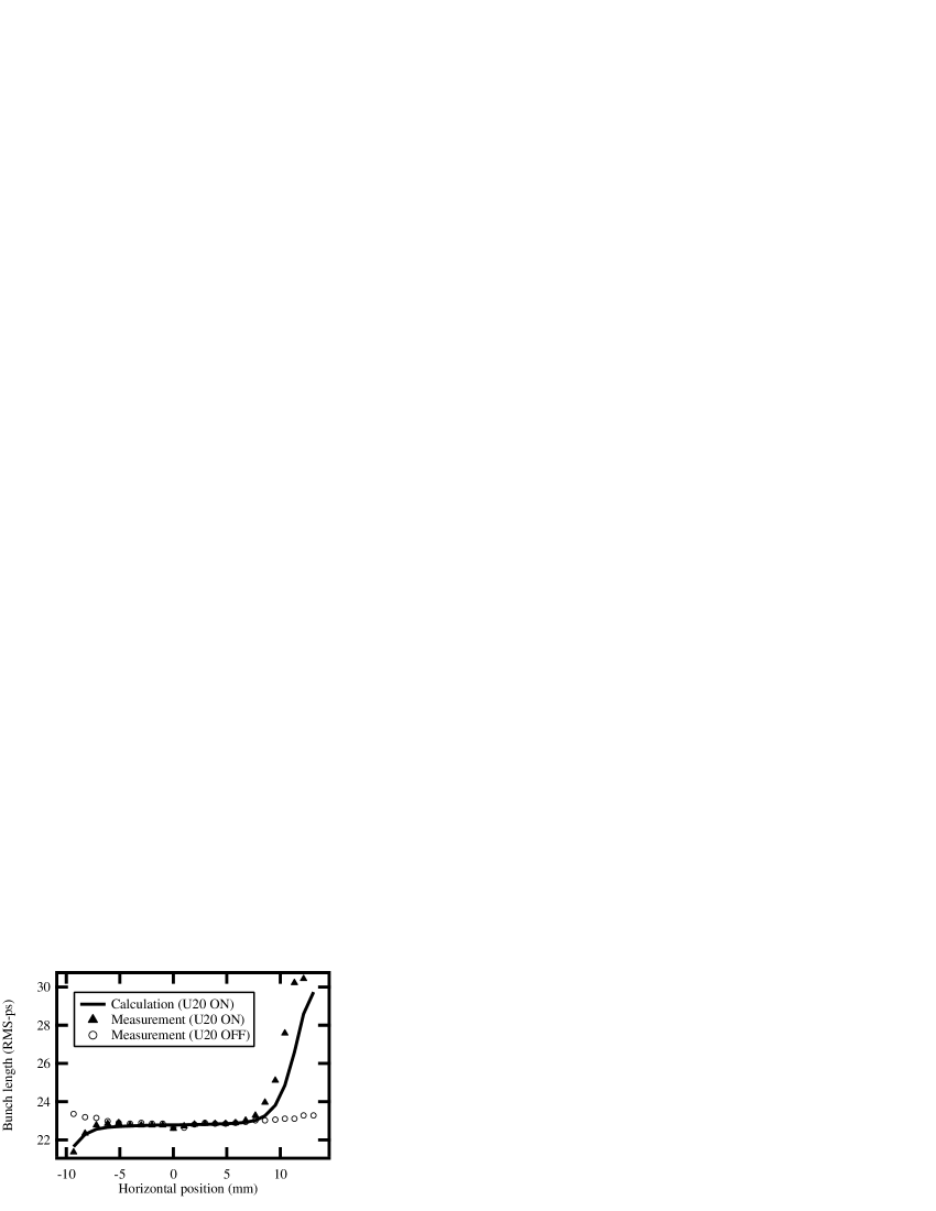
The bunch length is measured as a function of the horizontal position in the four U20s with a HAMAMATSU-C10910 Series streak camera Tordeux et al. (2007) of 2 ps-FWHM resolution to infer the effect on the energy spread (equation 11). Figure 8 shows a typical bunch image detected by the streak camera. Figure 9 compares the measured bunch length with that obtained with equation 11 using the damping partition due to the four U20s closed at minimum gap found in Fig. 6. Bunch length calculations assumes to be constant as a function of the horizontal position as predicted by AT simulation, MV, , GeV, kHz and the energy spread calculated with equation 9 assuming constant natural energy spread ( ) over the whole horizontal range as predicted by AT simulation, and the damping partition found in Fig. 6.
Measurements confirm the expected increase of bunch length when U20s are closed at minimum gap due to the increase of the energy spread. However, measurements are less in accordance with calculations at large bump values because during the experiment it was not possible to displace the electron beam so that its horizontal position is exactly the same in the four U20s.
II.4 Measurement of Robinson effect on the transverse beam properties
Figure 10 shows the horizontal beam size as a function of the horizontal beam position in the four U20s measured with a pinhole camera Labat et al. (2007) of 5 precision to deduce the effect on the horizontal beam emittance (equation 1), taking into account the corresponding measured energy spread and the horizontal beam size expected from theoretical calculations using equation 1, where is the calculated energy spread (see Fig. 9), and are the optical functions at the pinhole camera obtained with AT simulation (see Fig. 4) and is the horizontal beam emittance calculated with equations 7 and 13 and the optical functions and (see Fig. 7).
The horizontal beam size reduction due to the Robinson effect expected at mm is confirmed by experimental observations. At large bump values, a slight shift between measurements and calculations appears because the horizontal beam position is not exactly the same in the four U20s.

III Expected spectral performance
Following the experimental observation of Robinson effect, the radiation properties of already installed undulators are studied under the modifications introduced by a RW with SRW (Synchrotron Radiation Workshop) code Chubar and Elleaume (1998). The undulator HU640 operating at low photon energy range in the linear horizontal polarization, and the U20 undulator operating at high photon energy range, are supposed to be installed in a new machine whose emittance and energy spread are modified by a RW while assuming unperturbed dispersion and betatron functions. (see Table 3 for the main characteristics of both undulators).
| Undulator | HU640 | U20 |
| Technology | Electromagnetic | HPM 111HPM: Hybrid Permanent Magnet, in-vacuum |
| 0.15 T | 1.08 T | |
| Period length | 640 mm | 20 mm |
| 8.95 | 2 | |
| Energy range | (5-40) eV | (3-18) keV |
| Straight section | Long | Short |


The effect on the spectrum can be understood by considering the various contributions of the spectral broadening . For a mono-energetic filament electron beam, the undulator line presents a natural linewidth with the harmonic number and the number of the undulator periods, the inhomogeneous broadening due to the emittance with the relativistic factor and the deflection parameter of the undulator, the inhomogeneous broadening due to the energy spread and the inhomogeneous broadening due to the beam size at a distance where the radiation is collected. Consequently, the total spectral broadening can be expressed as:
| (14) |
Figure 11 compares the calculated flux density emitted by the HU640 undulator considering the present SOLEIL horizontal emittance and energy spread, and that modified due to the assumed presence of a RW. The flux density emitted by the HU640 for the first (H1) and the third (H3) harmonics remains practically unchanged. The harmonic H1 is unaffected whereas the H3 flux is reduced by . The harmonic widths are mostly determined by the energy spread, since , while and (calculated at the source point: m, m, rad, rad). As the contribution of the energy spread is independent of the harmonic number, the effect of the energy spread on the lower order harmonics combines with the homogeneous linewidth, whereas for higher order harmonics the broadening is mainly determined by the energy spread. Given that the HU640 is composed of 14 periods, then for H1, and for H3.


Figure 12 compares the calculated flux density emitted by the U20 undulator operating in the high energy range considering the present SOLEIL horizontal emittance and energy spread and that modified due to the assumed presence of a RW. The flux density of the harmonic H1 is not affected and that of the harmonic H11 is reduced by about . The different contributions to the total harmonic broadening are: , and (calculated at the source point: m, m, rad, rad). Concerning the harmonic H1, the homogeneous linewidth dominates the effects of the energy spread (, the U20 is composed of 98 periods). Flux reduction noticed of the harmonic H11 is due to the combinaion between the energy spread and the homogeneous linewidth ().
Increasing the energy spread has a greater effect on the harmonic intensity for the U20 undulator compared to the HU640 one due to larger contribution of the emittance and the energy spread to the inhomogeneous broadening in the case of the U20. In addition, the homogeneous broadening is larger for the HU640 than for the U20.
IV Conclusion
The Robinson effect was observed and validated experimentally at SOLEIL. This novel development is a critical step forward achieved even without constructing a RW. The experiment was performed by making use of the high field and field gradient of already installed undulators in the storage. The expected Robinson effects on reducing the horizontal emittance and increasing the energy spread are observed in agreement with theoretical expectations: horizontal emittance is reduced by ratio of 35 and the energy spread is increased by ratio of 30 with respect to the present values. RW has an impact on the spectral distribution of the photon flux density emitted by insertion devices. In the low energy range it leads to a very tiny photon flux reduction, while in the high energy range it has a much larger effect on the photon flux. This makes a RW not a good candidate for synchrotron radiation facilities, but an excellent candidate for machines providing collision experiments which require beams of tiny dimensions.
Acknowledgements.
The author would like to acknowledge Ryutaro Nagaoka from Synchrotron SOLEIL for reviewing this manuscript and for giving his time for continuous and constructive discussions.References
- Lengeler (2001) B. Lengeler, Naturwissenschaften 88, 249 (2001).
- Huang et al. (2013) Z. Huang et al., Brightness and coherence of synchrotron radiation and FELs, Tech. Rep. (SLAC National Accelerator Laboratory (SLAC), 2013).
- Miao et al. (1999) J. Miao, P. Charalambous, J. Kirz, and D. Sayre, Nature 400, 342 (1999).
- Kondratenko and Skrinsky (1977) A. Kondratenko and A. Skrinsky, Optics and Spectroscopy 42, 189 (1977).
- Kim (1987) K.-J. Kim, Nuclear Instruments and Methods in Physics Research Section A: Accelerators, Spectrometers, Detectors and Associated Equipment 261, 44 (1987).
- Krinsky (1983) S. Krinsky, IEEE Transactions on Nuclear Science NS-30, 3078 (1983).
- Tanaka and Kitamura (2009) T. Tanaka and H. Kitamura, Journal of Synchrotron Radiation 16, 380 (2009).
- Nadji et al. (2011) A. Nadji, P. Brunelle, M.-E. Couprie, J.-C. Denard, J.-M. Filhol, J.-F. Lamarre, P. Lebasque, A. Loulergue, P. Marchand, R. Nagaoka, and M.-A. Tordeux, in Proceedings of IPAC11 (San Sebastian, Spain, 2011) pp. 3002–3004.
- Bartolini (2007) R. Bartolini, in Proceedings of PAC07 (New Mexico, USA, 2007) pp. 1109–1111.
- Borland (2013) M. Borland, Journal of Physics: Conference Series, 425, 042016 (2013).
- Hettel (2014) R. Hettel, Journal of Synchrotron Radiation 21, 843 (2014).
- Lee (2004) S.-Y. Lee, Accelerator Physics (World Scientific Publishing Co Inc, 2004).
- Wiedemann (1988) H. Wiedemann, Nuclear Instruments and Methods in Physics Research Section A: Accelerators, Spectrometers, Detectors and Associated Equipment 266, 24 (1988).
- Courant and Snyder (1958) E. Courant and H. Snyder, Annals of Physics 3, 1 (1958).
- Bengtsson (2008) J. Bengtsson, in Proceedings of EPAC08, invited (Genoa, Italy, 2008) pp. 988–992.
- Berz et al. (2015) M. Berz, K. Makino, and W. Wan, An introduction to beam physics (Taylor and Francis, 2015) p. 230.
- Einfeld et al. (1995) D. Einfeld, J. Schaper, and M. Plesko, in Proceedings of PAC95 (Dallas, Texas, 1995) pp. 177–179.
- Leemann et al. (2009) S.-C. Leemann, A. Andersson, M. Eriksson, L.-J. Lindgren, E. Wallén, J. Bengtsson, and A. Streun, Phys. Rev. ST Accel. Beams 12, 120701 (2009).
- Tavares et al. (2014) P.-F. Tavares, S.-C. Leemann, M. Sjöström, and A. Andersson, Journal of synchrotron radiation 21, 862 (2014).
- Eriksson et al. (2016) M. Eriksson, L. Malmgren, E. Al-Dmour, S. Thorin, M. Johansson, S.-C. Leemann, A. Andersson, and P.-F. Tavares, in proceeding of IPAC16 (Chicago, IL, USA, 2016) pp. 439–444.
- Tsumaki and Kumagai (2006) K. Tsumaki and N. Kumagai, Nuclear Instruments and Methods in Physics Research Section A: Accelerators, Spectrometers, Detectors and Associated Equipment 565, 394 (2006).
- Tanaka et al. (2016) H. Tanaka, S. Goto, T. Ishikawa, S. Takano, T. Watanabe, and M. Yabashi, in Proceedings of IPAC16 (Busan, Korea, 2016) pp. 2867–2870.
- Biasci et al. (2014) J.-C. Biasci, J.-F. Bouteille, N. Carmignani, J. Chavanne, D. Coulon, Y. Dabin, F. Ewald, L. Farvacque, L. Goirand, M. Hahn, J. Jacob, G. LeBec, S. Liuzzo, B. Nash, H. Pedroso-Marques, T. Perron, E. Plouviez, P. Raimondi, J.-L. Revol, K. Scheidt, and V. Serrière, Synchrotron Radiation News 27, 8 (2014), https://doi.org/10.1080/08940886.2014.970931 .
- Raimondi (2016) P. Raimondi, in Proceedings of IPAC16 (Busan, Korea, 2016) pp. 2023–2027.
- Borland (2012) M. Borland, Exploration of a Tevatron-sized ultimate storage ring, Tech. Rep. (Argonne National Laboratory (ANL), 2012).
- Emma and Raubenhemier (2001) P. Emma and T. Raubenhemier, Phys. Rev. ST Accel. Beams 4, 021001 (2001).
- Tischer et al. (2005) M. Tischer, K. Balewski, W. Decking, M. Seidel, L. Yongjun, P. Vobly, V. Kuzminykh, K. Zolotariov, and E. Levichev, in Proceedings of PAC 2005 (Knoxville, Tennessee, 2005) pp. 2446–2448.
- Guo et al. (2009) W. Guo, S. Kramer, S. Krinsky, Y. Li, B. Nash, and T. Tanabe, in Proceedings of PAC09 (Vancouver, BC, Canada, 2009) pp. 1102–1104.
- Nosochkov et al. (2011) Y. Nosochkov, K. Bane, Y. Cai, R. Hettel, and M.-H. Wang, in Proceedings of IPAC11 (San Sebastian, Spain, 2011) pp. 3068–3070.
- Robinson (1958) K. Robinson, Physical Review 111, 373 (1958).
- Hofmann (1967) A. Hofmann, in proceedings of ICHEA (1967).
- Baconnier et al. (1985) Y. Baconnier, R. Cappi, J.-P. Riunaud, H.-H. Umstätter, M.-P. Level, M. Sommer, and H. Zyngier, Nuclear Instruments and Methods in Physics Research Section A: Accelerators, Spectrometers, Detectors and Associated Equipment 234, 244 (1985).
- Li et al. (2013) J. Li, G. Liu, W. Xu, and W. Li, in Proceedings of IPAC13 (Shanghai, China, 2013) pp. 2009–2011.
- Tian et al. (2017) S.-Q. Tian, Q.-L. Zhang, M.-Z. Zhang, K. Wang, and B.-C. Jiang, Nuclear Science and Techniques 28, 9 (2017).
- Goetsch et al. (2014) T. Goetsch, J. Feikes, M. Ries, and G. Wüstefeld, in Proc. IPAC14 (Dresden, Germany, 2014) pp. 2001–2003.
- Tydecks (2016) T. Tydecks, A Robinson Wiggler for the Metrology Light Source, Ph.D. thesis, Berlin University (2016).
- Abualrob et al. (2012) H. Abualrob, P. Brunelle, M.-E. Couprie, O. Marcouillé, A. Nadji, L. Nadolski, and R. Nagaoka, in Proceedings of IPAC12 (New Orleans, USA, 2012) pp. 702–704.
- Sands (1971) M. Sands, The Physics of Electron Storage Rings. An Introduction (SLAC-R-121, 1971).
- Benabderrahmane et al. (2007) C. Benabderrahmane, P. Berteaud, F. Briquez, P. Brunelle, O. Chubar, M.-E. Couprie, J.-M. Filhol, M. Girault, O. Marcouillé, F. Marteau, M. Massal, F. Paulin, M. Valleau, and J. Veteran, in Proceedings of PAC07 (Albuquerque, New Mexico, USA, 2007) pp. 929–931.
- Couprie et al. (2010) M.-E. Couprie, C. Benabderrahmane, P. Berteaud, F. Briquez, L. Chapuis, O. Chubar, T. Elajjouri, F. Marteau, J.-M. Filhol, C. Kitegi, O. Marcouillé, M. Massala, M. Valleau, and J. Vétéran, in Proceedings of AIP Conference, Vol. 1234 (AIP, 2010) pp. 519–522.
- Elleaume et al. (1997) P. Elleaume, O. Chubar, and J. Chavanne, in Proceedings of PAC97 (Vancouver, Canada, 1997) pp. 3509–3511.
- Chubar et al. (1998) O. Chubar, P. Elleaume, and J. Chavanne, Journal of Synchrotron Radiation 5, 481 (1998).
- Terebilo (2001) A. Terebilo, Performance Issues at Synchrotron Light Sources, Advanced Light Source, Lawrence Berkeley Lab, Berkeley CA USA (2001).
- Tordeux et al. (2007) M.-A. Tordeux, L. Cassinari, O. Chubar, J.-C. Denard, D. Pédeau, and B. Pottin, in Proceedings of DIPAC07 (Venice, Italy, 2007) pp. 180–182.
- Labat et al. (2007) M. Labat, L. Cassinari, M.-E. Couprie, R. Nagaoka, and D. Pédeau, in Proceedings of DIPAC07 (Venice, Italy, 2007) pp. 241–243.
- Chubar and Elleaume (1998) O. Chubar and P. Elleaume, in Proceedings of EPAC98 (Stockholm, Sweden, 1998) pp. 1177–1179.
- (47) http://www.hamamatsu.com.