A hybrid ring design in the storage-ring proton electric dipole moment experiment
Abstract
A new, hybrid design is proposed to eliminate the main systematic errors in the frozen spin, storage ring measurement of the proton electric dipole moment. In this design, electric bending plates steer the particles, and magnetic focusing replaces electric. The magnetic focusing should permit simultaneous clock-wise and counter-clock-wise storage to cancel systematic errors related to the out-of-plane dipole electric field. Errors related to the quadrupole electric fields can be eliminated by successive runs of magnetic focusing with different strengths.
I Introduction
CP-violation is a necessary condition of the observed baryon-antibaryon asymmetry in our universe. sakharov However, the CP-violating phase in weak interactions and the P- and T-violating -term of quantum chromodynamics (QCD) in the standard model (SM) are not enough to explain that asymmetry. A new, much stronger CP-violating source is needed, probably from physics beyond the SM, e.g., super-symmetry (SUSY). EDM searches are some of the most sensitive probes of physics beyond the SM associated with CP-violation. landau ; susyref ; lrsref ; higgsref ; dipole_moments ; engel13
The neutron EDM (nEDM), electron EDM (eEDM), and 199Hg EDM experimental sensitivities are currently the most advanced ones and set the most restrictions in the relevant parameter space. The current (direct) limit of the nEDM is , baker the eEDM limit (indirect, from the study of ThO molecules) is , baron and the 199Hg experimental EDM limit . moledm The SM contribution from the electro-weak sector for hadronic EDMs is at the level, while the -term contributes pospelov as
| (1) |
meaning from the nEDM limit that , while from the theory of QCD it was expected to be of order 1. To solve this apparent discrepancy, for an otherwise very successful theory, Peccei and Quinn came up with a new symmetry, peccei the breakdown of which requires the existence of axions. weinberg ; wilczek ; kim ; shifman ; zhitnitsky ; dine With or without this axion field, the contribution of the -term can be anywhere below the current experimental limits. In addition, physics beyond the SM, e.g., SUSY, is also possible anywhere below the present experimental limits. The contributions of the different potential sources combine in different ways in different systems, so more than one system is needed to decipher the CP-violating source should one be found to be non-zero. engel13 The mercury atomic EDM limit translates to for the neutron and for the proton, i.e., setting the most precise experimental limits for those systems.
The storage ring EDM method is proposed to reach below , targeting with an upgrade. This sensitivity goal is possible due to the high intensity polarized beams available, the long spin coherence time, and the high analyzing power for magic momentum protons. In this document we will suggest a modification to the original all-electric storage ring method to reduce the risk of the main systematic error, that of the radial B-field present around the ring. The new method uses a series of different strength measurements using magnetic alternating focusing in order to be able to differentiate between a genuine EDM effect and an effect originating from other, background-related sources. According to our precision simulations we expect to be able to simultaneously store counter-rotating beams, which will help minimize systematic errors by several orders of magnitude. Some runs may include different strength electric focusing for systematic error studies.
II Experimental Method using a hybrid ring lattice
The magnetic dipole moment (MDM) , and EDM of a particle with rest-frame spin , charge , and mass are defined as and , with the g-factor and playing the same role for EDM as is playing for the MDM. At rest, the spin precession rate of a particle in magnetic and electric fields is given by
| (2) |
However, in a storage ring the spin precession is modified by the Thomas term due to the angular acceleration and it is described by the T-BMT bmt ; fukuyama ; khriplovich equation, assuming ,
| (3) | ||||
where , , and is the relativistic Lorentz factor. It is evident that for a charged particle at rest, applying a net electric field to probe its EDM is not an option, as the particle will be accelerated and get lost very fast. Even though the EDM of charged particles has been probed in storage rings, muonedm1 ; muonedm2 one way to improve the sensitivity to the EDM of charged particles is the frozen spin method, far ; orlov ; nel ; mane1 ; mane2 ; protonEDMprop ; rsi where the spin is kept along the momentum vector and the radial electric field is acting on the particle EDM for the duration of the storage time. An all-electric ring, albeit smaller by an order of magnitude, is already constructed and operated at Heidelberg. essr3 The all-electric ring allows for simultaneous clock-wise and counter-clock-wise storage. A net radial B-field around the ring (, with the Fourier component of the radial B-field around the ring azimuth) will cause an EDM-like signal by precessing the particle spin similarly to an EDM precession.
The new experimental approach suggested here is superior to the previously proposed method in that by using a series of measurements with different strength alternating magnetic focusing we can distinguish a genuine EDM signal from a background one, reducing the effect of major potential systematic error sources by several orders of magnitude. As part of the systematic error studies, weak electric focusing may also be included. The simulations used here are based on Runge-Kutta integration. hamming59 ; selcuk ; mane15
The radial B-field modes constitute a serious systematic error in the all-electric storage ring EDM experiment. Our plan to reduce this field with shielding works best when the vertical beta-function is uniform around the ring. In that case, only the mode of the radial B-field produces a non-zero vertical spin precession rate. The effect of the non-uniform vertical beta-function carli is to produce a significant vertical spin precession rate due to the high modes of the radial B-field. Here we summarize the current situation and suggest a way to differentiate the effect of the radial B-field from a genuine EDM effect after applying magnetic focusing instead of electric focusing. The original idea to cancel the radial B-field effect was based on the assumption that the main background originates only from the (DC) component of the radial B-field. The higher modes were considered to be harmless, except from the possibility of confusing the interpretation of the SQUID-based beam position monitors (BPMs). Hence,
-
1.
Our plan was to reduce the BPM sensitivity to higher modes. Shield the magnetic fields to 1-10 nT everywhere around the ring. Even though the geometrical phase effects due to the magnetic fields cancel with CW and CCW injections, this level of shielding is considered easily achievable with present day technology, so it is our goal. selcuk_sh
-
2.
The time stability of the shielded horizontal B-field from our measurements is at the level of 100 pT per 10 minutes with a longitudinal gradient of its radial component of about 5 pT/m. This time stability is adequate for the needs of the experiment to the required level. selcuk_sh
-
3.
The goal of reducing the higher than radial B-field modes was solely based on the impression that they were harmless regarding the spin precession rate and therefore all the effort was focused on reducing their impact on the SQUID-based BPM output. Indeed, the SQUID-based BPM signals in a lattice with uniform beta-functions scale as for time modulated focusing quads (and for value), so that they would not compete as a background with the EDM signal. rsi ; kawall
After Christian Carli demonstrated that the non-uniform vertical beta-function has a profound effect on the vertical spin precession rate we considered a number of possible plans to reduce the experimental sensitivity to radial B-field modes with . The value of was chosen because we had assumed 20 SQUID-based BPMs, equally spaced around the ring and hence we could detect all the modes up to and including the mode. rsi
-
1.
One of us (S. H.) suggested using a combination of different lattices to decipher the beam dynamics resonances responsible for the vertical spin precession rate. The studies have shown significant promise to warrant more investigation in this direction.
-
2.
Design a ring with as uniform vertical beta-function as possible. Having a completely uniform focusing ring may be possible; however, taking this approach will require a long and detailed study to make it compatible with all the additional requirements and effects in our experiment. It will also require a long and detailed study on the subject to come up with a credible lattice design and even though it may be worthwhile to explore this option, next we propose a simpler approach.
-
3.
The new idea is to use magnetic instead of electric focusing in the ring. We have demonstrated that we could store beams CW and CCW at the same time when using alternating magnetic focusing, making this possibility feasible. This fact is critical since the inescapable vertical E-field effect from a misaligned radial E-field plate is also an important systematic error source. deuteron
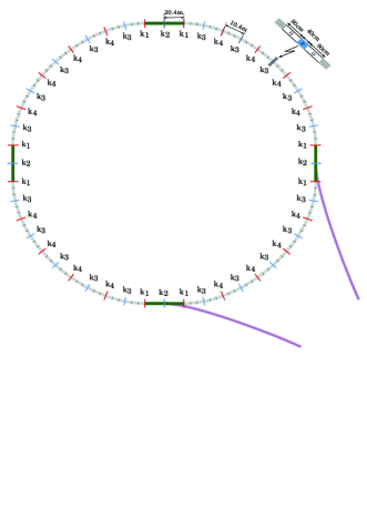
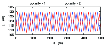
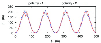
The counter-rotating beams do not actually go through the same places everywhere, due to the fact that the vertical focusing includes magnetic focusing. Therefore, those beams may not exactly cancel those systematic errors at all places. However, we have shown that it is possible to use the same magnetic quads with flipped field directions (opposite sign currents) and on average the particles do follow the same trajectories. The study showed that this approach is very promising. This idea seems to work perfectly well, eliminating completely the radial B-field issue. In addition, the vertical dipole E-field effect is cancelled completely in CW and CCW injections as is the effect of gravity. The suggested working lattice is shown in Figure 1, which is a modification of the lattice shown in the paper rsi describing the all-electric storage ring method, but this time the electric quadrupoles are replaced with corresponding magnetic ones. Figure 2 shows the vertical beta-function of the CW and CCW stored beams, and Figure 3 the corresponding for the horizontal. Flipping the sign of the currents in the magnetic quadrupoles will produce symmetric beta-functions for the CW and CCW beams.
However, it is always possible that some electric focusing will be present somewhere in the ring. This focusing and/or defocusing could originate from the bending electric field plates, which produce the required radial E-field. One or both plates could be misaligned, readily producing a vertical dipole, but also a quadrupole or even higher multipole E-fields. There could also exist induced charges (image charges) from any horizontally placed metals around the lattice, the tune shift and tune spread effects due to high beam intensities, etc. Some of those systematic errors we may be able to detect, e.g., by modulating the voltage on the bending E-field plates or control them by using beam bunch intensities of various strengths. At the end of the experiment, however, we need to have high confidence regarding the origin of the effect. Here we are suggesting using a number of runs with different vertical magnetic focusing strengths in order to differentiate between a systematic error and a genuine EDM signal.
The total effect, i.e. the vertical spin precession rate, is going to be in a functional form:
| (4) |
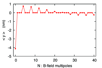
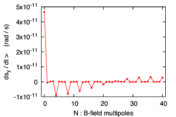
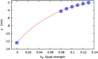
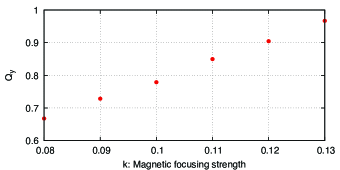
where is referring to the total vertical spin precession rate, refers to the portion due to the particle EDM, corresponds to the square of the tuning due to non-magnetic effects, is the square of the tune due to the magnetic quads, , , are the square of the tunes due to the electric quads, the forces due to induced charges, and the forces due to the beam intensity, correspondingly. refers to the vertical spin precession rate due to the radial B-field. The point is that a net radial B-field can create a vertical spin precession, which can only be canceled exactly by another B-field; in this case we assumed it to be the magnetic focusing. Magnetic focusing can essentially eliminate this systematic error provided that it is the only source focusing the beam. Figure 4 shows the average vertical offset of the stored beam as a function of the radial B-field multipole whose amplitude is always kept at 1 pT. Figure 5 shows the vertical spin precession rate under the same conditions. A genuine EDM signal for is larger than 1 nrad/s, and therefore much larger than the above background signal. However, if on one of the magnetic quadrupoles we add an overlapping electrical quadrupole with a strength of 1 kV/m2, then we get the much larger spin precession rate of 0.4 nrad/s, for harmonic case of the radial B-field. This effect will be further and effectively suppressed by applying varying levels of magnetic field focusing, as described in the section below. Figure 6 shows the average vertical offset of the beam as a function of the magnetic focusing strength for the radial B-field multipole whose amplitude is always kept at 1 pT. Figure 7 shows the vertical tune vs. the magnetic focusing strength in the presence of an electrical focusing field of due to the shape of the electrical deflectors.
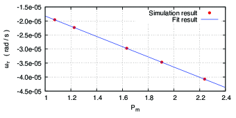
Experimental Approach. A practical way to proceed would be to first apply weak E-focusing and run the experiment for a number of fills. We can then apply the appropriate radial B-field to cancel the and higher radial B-field modes depending on the vertical spin precession rates and the SQUID-based BPM signals. (Note: Another large potential systematic error is due to orbit corrugation, i.e., the orbit non-planarity. However, this effect goes as the sine of the horizontal spin angle relative to momentum and it can be probed by a beam bunch whose spins are frozen in the radial direction. deuteron ; sredm_coll ) Next, we apply a series of B-field focusing strengths, from weak to stronger ones to probe the EDM effect. With magnetic focusing the main systematic error is the out-of-plane dipole electric field, which is cancelled by CW and CCW beam storage as in the deuteron storage ring EDM experiment. deuteron Since simultaneous CW and CCW storage is possible in the current configuration, then most of the issues related to E-field direction stability go away. In addition, any focusing effect from the electric field plates or any other sources is sorted out by running the experiment at different alternating magnetic focusing strengths as shown in Figure 8. Here, an additional electric focusing exists together with a DC () radial magnetic field around the ring with strength of 1 pT. The electric focusing is originated by shaping all the bending plates, producing a vertical focusing with a field index of . The spin precession rate equation, when expanded, can be written as
| (5) |
with , showing clearly that for a large magnetic focusing tune, i.e., , the spin precession rate corresponds to the EDM signal. Hence, the DC offset in Figure 8 corresponds to the EDM signal and the obtained value is consistent with the simulations. In Figure 8, the spin precession rate corresponds to EDM level to prove the principle of the method. It will be advantageous to keep the spin precession rate lower by adding much stronger magnetic focusing cases and keep the electric focusing below the level. The method will work best, requiring less leverage, when the magnetic focusing is dominating all other focusing effects. In a similar way, we can prove that the sextupole vertical electric field cancels with CW and CCW storage, etc., provided that the beam emittances are the same to an adequate level. From our simulations we infer that the SQUID-based BPMs resolution requirements are relaxed by several orders of magnitude over the lattice where electric focusing is used, which is a major breakthrough. The new requirements are a well-shaped quadrupole magnetic field in the ring, so that the center of the CW and CCW beams overlap within 100 nm at all magnetic quadrupole strengths, using the SQUID-based BPM signals. In addition, the ring needs to be flat (absence of corrugation) to 100 nrad, which we achieve by a combination of mechanical alignment, beam-based alignment and by using bunches polarized in the radial direction. A summary of the main systematic errors in the experiment with hybrid fields (electric bending and magnetic focusing) and their current remediation plan is given in Table 1.
| Effect | Remediation |
|---|---|
| Radial B-field. | Magnetic focusing. |
| Radial B-field when | Varying magnetic focusing |
| other than magnetic | and fit for the DC offset in the |
| focusing is present. | vertical precession rate. |
| Dipole vertical E-field. | CW and CCW beam storage. |
| Corrugated (non-planar) | Probe with stored beams with their |
| orbit. | spins frozen in the radial direction. deuteron ; sredm_coll |
| RF cavity misalignment | Vary the longitudinal lattice impedance to probe the effect of the cavity’s vertical angular misalignment. CW and CCW beams cancel the effect of a vertically misplaced cavity. rsi |
III Conclusions
We have suggested a hybrid storage ring EDM method, where the focusing is solely done by alternating focusing magnetic fields, while the horizontal bending is accomplished by vertical (ideally strictly cylindrical) electro-static plates. This configuration allows the simultaneous storage of CW and CCW beams, enabling the cancelation of the main systematic error in this case, that of the dipole vertical E-field. The effect of the radial B-field as a background is cancelled by the magnetic focusing, while that of the electric quadrupole focusing is diminished by taking a number of runs with different vertical magnetic focusing strengths. This new conceptual improvement greatly relaxes the magnetic shielding requirements of the ring, improving the feasibility of the target sensitivity of cm and possibly beyond.
IV Acknowledgements
IBS-Korea (project system code: IBS-R017-D1) supported this project. We acknowledge useful discussions with members of the srEDM and JEDI collaborations, as well as our colleagues from CERN, specifically Christian Carli, Michael Lamont, Hans Stroeher, Richard Talman and others. We especially thank Sidney Orlov for greatly improving the readability of the paper.
References
- (1) A.D. Sakharov, “Violation of CP invariance, C asymmetry, and baryon asymmetry of the universe.” JETP Lett. 5 (1967): 24-27.
- (2) L. Landau, “On the conservation laws for weak interactions.” Nuclear Physics 3.1 (1957): 127-131.
- (3) D. Chang, W. Keung, and A. Pilaftsis, “New two-loop contribution to electric dipole moments in supersymmetric theories.” Physical Review Letters 82.5 (1999): 900.
- (4) C.Q. Geng and J.N. Ng, “CP-violation in , decays and electric dipole moments of electron and muon.” Physical Review D 42.5 (1990): 1509.
- (5) V. Barger, A. Das, and C. Kao, “Electric dipole moment of the muon in a two Higgs doublet model.” Physical Review D 55.11 (1997): 7099.
- (6) A. Czarnecki and W. Marciano in Lepton Dipole Moments, edited by L. Roberts and W. Marciano (World Scientific, Singapore, 2010). ISBN: 978-981-4271-83-7
- (7) J. Engel, M.J. Ramsey-Musolf, and U. van Kolck, “Electric dipole moments of nucleons, nuclei, and atoms: The standard model and beyond.”Journal of Progress in Particle and Nuclear Physics 71 (2013): 21-74.
- (8) C.A. Baker et al., “Improved experimental limit on the electric dipole moment of the neutron.” Physical Review Letters 97.13 (2006): 131801.
- (9) J. Baron et al., “Order of magnitude smaller limit on the electric dipole moment of the electron.” Science 343 (2014): 269-272.
- (10) B. Granner et al., “Reduced limit on the permanent electric dipole moment of 199Hg.” Physical Review Letters 116 (2016): 161601.
- (11) M. Pospelov, A. Ritz, “Electric dipole moments as probes of new physics.” Ann. Phys. 318 (2005): 119.
- (12) R.D. Peccei and Helen R. Quinn, “CP conservation in the presence of pseudoparticles.” Physical Review Letters 38 (1977): 1440-1443.
- (13) S. Weinberg, “A new light boson?” Physical Review Letters 40 (1978): 223-226.
- (14) F. Wilczek, “Problem of strong P and T invariance in the presence of instantons.” Physical Review Letters 40 (1978): 223-226.
- (15) Jihn E. Kim, “Weak-interation singlet and strong CP invariance.” Physical Review Letters 43 (1979): 103-107.
- (16) M.A. Shifman, A.I. Vainshtein, and V.I. Zakharov, “Can confinement ensure natural CP invariance of strong interactions?” Nuclear Physics B 166 (1980): 493-506.
- (17) A.R. Zhitnitsky, “On possible suppression of the axion hadron interactions.” (In Russian.) Sov. J. Nucl. Phys. 31 (1980): 260.
- (18) M. Dine, W. Fischler, and M. Srednicki, “A simple solution to the strong CP problem with a harmless axion.” Physics Letters B 104 (1981): 199-202.
- (19) V. Bargmann, L. Michel, and V.L. Telegdi, “Precession of the polarization of particles moving in a homogeneous electromagnetic field.” Physical Review Letters 2.10 (1959): 435.
- (20) T. Fukuyama and A.J. Silenko, “Derivation of generalized Thomas-Bargmann-Michel-Telegdi equation for a particle with electric dipole moment.” International Journal of Modern Physics A 28.29 (2013).
- (21) I.B. Khriplovich, “Feasibility of search for nuclear electric dipole moments at ion storage rings.” Physics Letters B 444.1 (1998): 98-102.
- (22) G.W. Bennett et al., “Measurement of the negative muon anomalous magnetic moment to 0.7 ppm.” Physical Review Letters 92.16 (2004): 161802.
- (23) G.W. Bennett et al., “Improved limit on the muon electric dipole moment.” Physical Review D 80.5 (2009): 052008.
- (24) F.J.M. Farley et al., “New method of measuring electric dipole moments in storage rings.” Physical Review Letters 93.5 (2004): 052001.
- (25) Y.F. Orlov, W.M. Morse, and Y.K. Semertzidis, “Resonance method of electric-dipole-moment measurements in storage rings.” Physical Review Letters 96.21 (2006): 214802.
- (26) D.F. Nelson et al., “Search for an electric dipole moment of the electron.” Physical Review Letters 2.12 (1959): 492.
- (27) S.R. Mane, “Orbital dynamics in a storage ring with electrostatic bending.” Nuclear Instruments and Methods in Physics Research Section A 596.3 (2008): 288-294.
- (28) S.R. Mane, “Orbital and spin motion in a storage ring with static electric and magnetic fields.” Nuclear Instruments and Methods in Physics Research Section A 687 (2012): 40-50.
- (29) V. Anastassopoulos et al., “A proposal to measure the proton electric dipole moment with cm sensitivity,” by the Storage Ring EDM Collaboration, October 2011. Available from http://www.bnl.gov/edm/.
- (30) V. Anastassopoulos et al., “A storage ring experiment to detect a proton electric dipole moment.” Review of Scientific Instruments 87 (2016): 115116.
- (31) R. von Hahn et al., “The electrostatic cryogenic storage ring CSR - Mechanical concept and realization.” Nuclear Instruments and Methods in Physics Research B 269.24 (2011): 2871-2874.
- (32) R.W. Hamming, “Stable predictor-corrector method for ordinary differential equations.”Journal of the ACM (JACM), 6 (1959): 37-47.
- (33) S. Hacıömeroğlu and Y.K. Semertzidis, “Results of precision particle simulations in an all-electric ring lattice using fourth-order Runge-Kutta integration.” Nuclear Instruments and Methods in Physics Research A 743 (2014): 96-102.
- (34) S.R. Mane, “Comment on ‘Results of precision particle simulations in an all-electric ring lattice using fourth-order Runge-Kutta integration.’"Nuclear Instruments and Methods in Physics Research A 769 (2015): 26-31.
- (35) First pointed out by Christian Carli, private communication, November 2017. Essentially, the distribution of the background radial B-field can be on resonance with the lattice structure, creating a net vertical spin precession even for .
- (36) S. Hacıömeroğlu et al., “Prototype development of the magnetic shielding for the proton EDM experiment," to be published.
- (37) First pointed out by David Kawall, private communication, November 2014.
- (38) D. Anastassopoulos et al., “AGS Proposal: Search for a permanent electric dipole moment of the deuteron nucleus at the level,” by the Storage Ring EDM Collaboration, October 2008. Available from http://www.bnl.gov/edm/.
- (39) Internal presentations at storage ring EDM collaboration meetings, 2003.