Simulating Modulated X-ray calibration Sources for future X-ray missions, using GEANT4
Abstract
The XIFU X-ray spectrometer instrument on the future Athena mission needs X-ray calibration sources to calibrate the gains of the individual detector pixels. For this purpose, electronically controlled Modulated X-ray Sources (MXS) are proposed, similar to the calibrations sources used on the Hitomi spacecraft and which will also fly on its successor, XARM. Here we present a simulation package based on the particle transport GEANT4 toolkit. Using this package, we compute the results for different targets and window configurations for the MXS’s. The simulations expose the trade-offs to be made to select the optimum source configuration for the Athena/XIFU and XARM/Resolve spectrometer instruments.
1 INTRODUCTION
In astronomy, for future high resolution X-ray spectroscopic imaging, micro-calorimeter instruments are planned on the XARM[1] and Athena[2] satellites. The first time such an instrument was used for astronomical observations was on the Hitomi[3] (ASTRO-H) satellite. Its high spectral resolution observations of the Perseus cluster[4] did show that this type of instrument does open up a new window in the analysis of hot and energetic objects in the universe. Unfortunately this instrument was lost prematurely, due to early failure of the spacecraft.
Micro-calorimeters require regular careful calibration of their detector gains in order to obtain a reliable energy scale. For this, internal calibration sources are required, which provide a set of X-ray emission lines at known energies. In the past, X-ray instruments usually used radio-active sources for this purpose. Such sources are very stable, but do have the disadvantage of having only a limited number of lines and being continuously active.
For the Soft X-ray Spectrometer (SXS) instrument on Hitomi, a new type of electrically activated source was used: the Modulated X-ray Source (MXS). This source has the advantage that it can provide X-ray calibration lines at multiple energies and can be pulsed or switched off, to allow astronomical data to be taken during periods without a background from the calibration source. These sources consist of a photo-cathode, which generates electrons, which are accelerated towards an anode target, causing X-ray fluorescence lines to be emitted. For details on the Hitomi MXS sources, see e.g. references 5,6,7.
The same type of MXS calibration sources is planned for the spectroscopic instruments on the Hitomi successor, XARM, and the Athena satellite.
In order to properly design for optimal performance of these sources, and to explore the possibilities in terms of energy range (potential target materials) and operating conditions, a software package to simulate these sources is required. In this paper we present such a package based on the GEANT4[8, 9] particle transport toolkit.
2 MXS GEANT4 CONFIGURATION
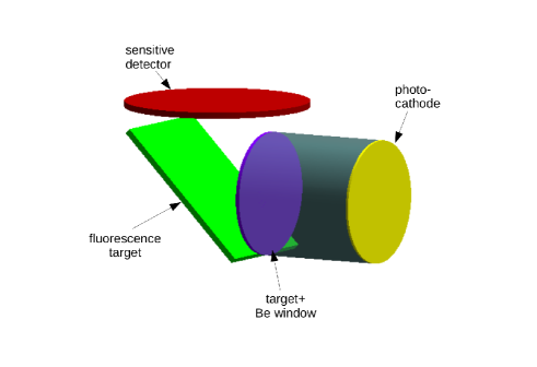
Two types of MXS sources exist: a direct source, in which the X-rays directly coming from the (internal) anode target, which is hit by the electrons, are used, and an indirect source, in which the direct X-rays hit an external fluorescence target, which then generate the X-ray emissions lines. On the MXS an X-ray transparent Beryllium(Be) window shields the high vacuum inside the source from the outside world. The internal X-ray target is deposited directly onto the Be window. The direct X-rays leave the MXS through the target and Be window. Figures 2 and 2 show the representation of these sources in the GEANT4 geometry (the DetectorConstruction class).
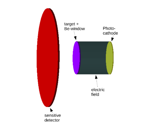
A uniform electric field is defined in between the cathode and the anode (X-ray target). Electrons are generated uniformly across the cathode and specified to leave the cathode with a negligible 3 eV energy. Subsequently the electrons are accelerated in the field towards the anode. Any electrons back-scattered from the anode will be redirected by the electric field, again towards the anode.
The electron interaction with the anode target and the subsequent propagation of any resulting X-ray photons is controlled by what is called the GEANT4 ”physicslist”. Given the MXS low energy range (¡ 12 keV), in our MXS ”physicslist” only electromagnetic processes for the electron and photon interaction are important. For photons, photoelectric and scattering processes are included. For the electrons, single and multiple scattering processes, ionization (PenelopeIonisationModel) and Bremsstrahlung are defined. Finally, atomic de-excitation physics adds X-ray fluorescence and Auger processes.
Finally, the ”sensitive detector” defines a volume which registers all the particles traversing this volume. For each registered particle, the nature of the particle is stored: the energy of the particle, the location where it originated and the physics process which generated the particle. This way, the performance of the MXS can be analyzed in detail.
To speed up processing, the GEANT4 code is started from a python111https://www.python.org/ script which splits (using open-mpi 222https://www.open-mpi.org/) the total number of electrons to be processed over multiple CPU’s (in a linux cluster environment) and at the end combines the output files into a single file which holds the registered events.
The MXS model configuration is controlled from an ASCII text file using GEANT4 ”G4UIcmd” command definitions. In this way the MXS configuration can be altered without recompiling the code. Configuration commands include:
-
•
magnitude of the accelerating voltage used.
-
•
material and thickness of the different anode targets
-
•
number of consecutive target layers
-
•
thickness of the Beryllium window
-
•
material of the optional external fluorescent target
-
•
total number of electrons to be processed
3 MODEL VALIDATION
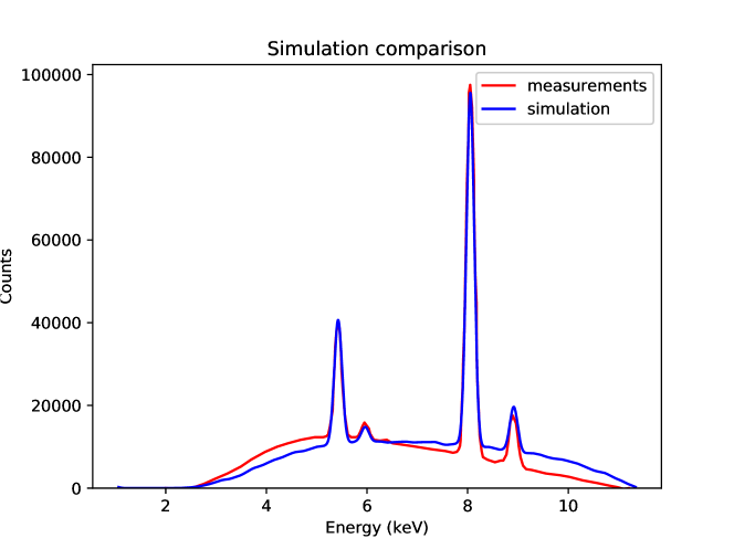
Figure 3 shows a comparison between a simulated and a measured spectrum for an MXS identical to the Hitomi MXS configuration. The simulated spectrum was convolved with the energy resolution of the Silicon Drift Detector(SDD) used to measure the spectrum from an actual real source. In addition the simulated spectrum was corrected for absorption by 8 cm of air, as was the case for the real measurements. The figure shows that the line ratios and the flux in the lines with respect to the Bremsstrahlung continuum match quite well. The shape of the Bremsstrahlung is a little different, but depends quite a bit on the exact match of the accelerating voltage (supposed to be 11.3 kV, but which has some margin of error (about kV) for the measurements). In addition, the decrease of SDD efficiency due to the limited thickness of the silicon of the detector has not been taken into account. Given these uncertainties the simulations match the measurements quite well.
The total number of photons generated in the source simulation was 145000 (of which 35000, or 24% are fluorescent events in the Cr-K and Cu-K lines at 5.41 and 8.04 keV respectively). Those events are recorded in the ”sensitive detector”. This volume is located at 0.9 cm from the Be window and has a radius of 1.5 cm. This means a solid angle of sr. On Hitomi the SXS array had pixels of 0.8 mm square at 87.5 cm from the MXS, corresponding to a solid angle of sr. Thus the count rate on a Hitomi SXS pixel is about part of the simulated count rate on the ”sensitive detector”. For 145000 counts this is equivalent to 0.04 counts/pixel.
For the simulations electrons from the photocathode were used. If this would have been delivered in one second this corresponds to a current of 0.32 nA. In the measurement setup the X-ray intensity, corrected for absorption in air, was set at counts/pixel/second. (The relatively large uncertainty stems from the estimated uncertainty in the measurement geometry about which part of the MXS window was visible from the SDD detector). To get 75 counts/pixel/second for the simulations we would need =800 nA. In the real experiment 850 nA was measured.
It can be concluded that the simulation matches the real MXS measurement quite well.
4 MODEL MXS CONFIGURATIONS FOR XARM AND ATHENA
4.1 The standard, higher energy, MXS source
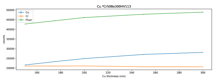
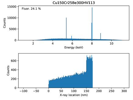
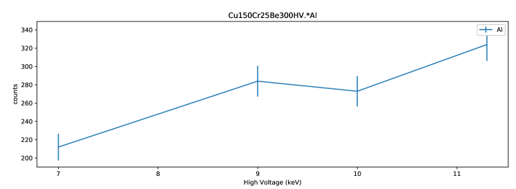
The GEANT4 model can be used to investigate optimum MXS source configurations and possibilities for the XARM and Athena missions. For the Hitomi SXS, a type of MXS was used which had an X-ray target of 25 nm of Cr on top of 150 nm of Cu, deposited on a 300 micron Be window. The design of these target thicknesses was based on very crude estimates of electron penetration in the targets. Now, with the current proper GEANT4 model, the optimum thicknesses of the targets can be computed far more accurately.
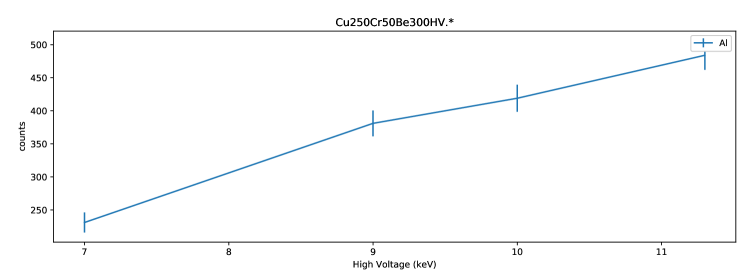
Fig. 4 shows the number of counts in the Cu and Cr fluorescent lines when the Cu target thickness is increased. The Cu fluorescent efficiency clearly increases while the Cr efficiency does not suffer. In Fig. 5 the Cr thickness is increased. Clearly the Cr fluorescent efficiency increases a lot, but there is some degradation of the Cu line intensity. This is due to the fact that the Cr is on top of the Cu and high energy electrons capable of activating the Cu are lost in the Cr layer.
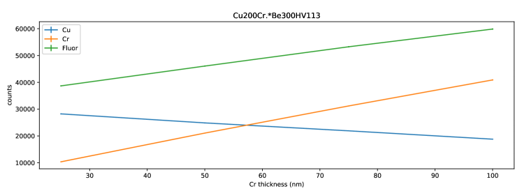
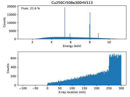
The optimum performance is for a source with 250 nm Cu and 50 nm Cr targets. Figures 7 and 7 compare the spectral performance of the old Hitomi MXS and the proposed optimum (XARM/Athena) MXS. It can be seen, that due to the thicker targets, the stream of electrons from the cathode will be used more effectively, reflected by the additional decline of the generated fluorescent X-rays per unit volume in the additional target material towards the Be window. This leads to a higher source efficiency.
4.2 A proposed lower energy MXS source for Athena
To check for non-linearities in the detector gain over the entire energy range, calibration emission lines over a broad range of energies are needed. The Hitomi and proposed XARM direct calibration sources provide lines (Cr,Cu) in the 5 - 9 keV energy range. For lower energy calibration lines, sources with an external fluorescent target (the indirect sources) were used. The problem with these sources is that they have very low efficiency. For low energy sources for the Athena XIFU instrument a different approach is investigated.
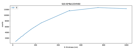
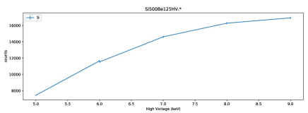
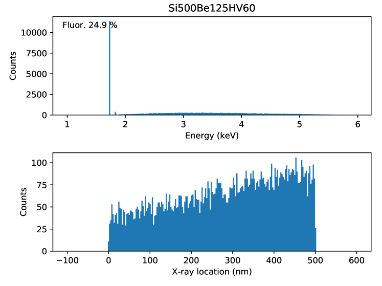
Problem with low energy targets within the MXS is that the Beryllium window can absorb a significant quantity of the flux. The standard 300 micron windows used in the Hitomi/XARM MXS’s is clearly too thick for low energy lines. A compromise is found in a 125 micron Beryllium window and a Silicon (Si) target on top of the window. This combination allows a source at relatively low energies (1.73 keV) with higher efficiency than an external target. For real low energies (Al, Mg lines at 1.25, 1.49 keV respectively) an external fluorescent target is still the only option.
Figures 9, 9 and 10 show the simulation results. Such a source can be driven by an accelerating voltage of 6 kV.
It is planned to test whether the 125 micron Beryllium window can withstand the mechanical stresses and maintain the high vacuum needed in the MXS’s, compared to the proven 300 micron thick windows in the Hitomi/XARM design.
4.3 The MXS with external fluorescent target
For the lowest energy lines, external fluorescent targets are needed. These fluorescent targets will be exited by the X-rays (Bremsstrahlung and line emission) from the MXS source. The simulation software can be used to test the efficiency as function of direct target configuration inside the MXS and accelerating voltage.
5 CONCLUSIONS
The GEANT4 simulation programs are a great tool in designing optimum performance MXS calibration sources. The MXS design for the future XARM/Resolve and Athena/XIFU instruments will benefit from this development. Based on the simulations the XARM/Resolve MXS calibration sources will have improved performance compared to its Hitomi predecessor, due to a change in target layer thickness. In addition the tools allow probing for the best operating voltage, and show the required photo-currents.
Acknowledgements.
The research leading to these results has received funding from the European Union’s Horizon 2020 Programme under the AHEAD project (grant agreement 654215).References
- [1] Tashiro, M. and Kelley, R., “The X-ray Astronomy Recovery Mission,” in [The X-ray Universe 2017 ], Ness, J.-U. and Migliari, S., eds., 219 (Oct. 2017).
- [2] Barret, D., den Herder, J. W., Piro, L., Ravera, L., Den Hartog, R., Macculi, C., Barcons, X., Page, M., Paltani, S., Rauw, G., Wilms, J., Ceballos, M., Duband, L., Gottardi, L., Lotti, S., de Plaa, J., Pointecouteau, E., Schmid, C., Akamatsu, H., Bagliani, D., Bandler, S., Barbera, M., Bastia, P., Biasotti, M., Branco, M., Camon, A., Cara, C., Cobo, B., Colasanti, L., Costa-Kramer, J. L., Corcione, L., Doriese, W., Duval, J. M., Fabrega, L., Gatti, F., de Gerone, M., Guttridge, P., Kelley, R., Kilbourne, C., van der Kuur, J., Mineo, T., Mitsuda, K., Natalucci, L., Ohashi, T., Peille, P., Perinati, E., Pigot, C., Pizzigoni, G., Pobes, C., Porter, F., Renotte, E., Sauvageot, J. L., Sciortino, S., Torrioli, G., Valenziano, L., Willingale, D., de Vries, C., and van Weers, H., “The Hot and Energetic Universe: The X-ray Integral Field Unit (X-IFU) for Athena+,” ArXiv e-prints (Aug. 2013).
- [3] Tsujimoto, M., Mitsuda, K., Kelley, R. L., den Herder, J.-W. A., Bialas, T. G., Boyce, K. R., Chiao, M. P., de Vries, C. P., DiPirro, M. J., Eckart, M. E., et al., “In-orbit operation of the soft x-ray spectrometer onboard the hitomi satellite,” Journal of Astronomical Telescopes, Instruments, and Systems 4(1), 011205 (2017).
- [4] Hitomi Collaboration, Aharonian, F., Akamatsu, H., Akimoto, F., Allen, S. W., Anabuki, N., Angelini, L., Arnaud, K., Audard, M., Awaki, H., Axelsson, M., Bamba, A., Bautz, M., Blandford, R., Brenneman, L., Brown, G. V., Bulbul, E., Cackett, E., Chernyakova, M., Chiao, M., Coppi, P., Costantini, E., de Plaa, J., den Herder, J.-W., Done, C., Dotani, T., Ebisawa, K., Eckart, M., Enoto, T., Ezoe, Y., Fabian, A. C., Ferrigno, C., Foster, A., Fujimoto, R., Fukazawa, Y., Furuzawa, A., Galeazzi, M., Gallo, L., Gandhi, P., Giustini, M., Goldwurm, A., Gu, L., Guainazzi, M., Haba, Y., Hagino, K., Hamaguchi, K., Harrus, I., Hatsukade, I., Hayashi, K., Hayashi, T., Hayashida, K., Hiraga, J., Hornschemeier, A., Hoshino, A., Hughes, J., Iizuka, R., Inoue, H., Inoue, Y., Ishibashi, K., Ishida, M., Ishikawa, K., Ishisaki, Y., Itoh, M., Iyomoto, N., Kaastra, J., Kallman, T., Kamae, T., Kara, E., Kataoka, J., Katsuda, S., Katsuta, J., Kawaharada, M., Kawai, N., Kelley, R., Khangulyan, D., Kilbourne, C., King, A., Kitaguchi, T., Kitamoto, S., Kitayama, T., Kohmura, T., Kokubun, M., Koyama, S., Koyama, K., Kretschmar, P., Krimm, H., Kubota, A., Kunieda, H., Laurent, P., Lebrun, F., Lee, S.-H., Leutenegger, M., Limousin, O., Loewenstein, M., Long, K. S., Lumb, D., Madejski, G., Maeda, Y., Maier, D., Makishima, K., Markevitch, M., Matsumoto, H., Matsushita, K., McCammon, D., McNamara, B., Mehdipour, M., Miller, E., Miller, J., Mineshige, S., Mitsuda, K., Mitsuishi, I., Miyazawa, T., Mizuno, T., Mori, H., Mori, K., Moseley, H., Mukai, K., Murakami, H., Murakami, T., Mushotzky, R., Nagino, R., Nakagawa, T., Nakajima, H., Nakamori, T., Nakano, T., Nakashima, S., Nakazawa, K., Nobukawa, M., Noda, H., Nomachi, M., O’Dell, S., Odaka, H., Ohashi, T., Ohno, M., Okajima, T., Ota, N., Ozaki, M., Paerels, F., Paltani, S., Parmar, A., Petre, R., Pinto, C., Pohl, M., Porter, F. S., Pottschmidt, K., Ramsey, B., Reynolds, C., Russell, H., Safi-Harb, S., Saito, S., Sakai, K., Sameshima, H., Sato, G., Sato, K., Sato, R., Sawada, M., Schartel, N., Serlemitsos, P., Seta, H., Shidatsu, M., Simionescu, A., Smith, R., Soong, Y., Stawarz, L., Sugawara, Y., Sugita, S., Szymkowiak, A., Tajima, H., Takahashi, H., Takahashi, T., Takeda, S., Takei, Y., Tamagawa, T., Tamura, K., Tamura, T., Tanaka, T., Tanaka, Y., Tanaka, Y., Tashiro, M., Tawara, Y., Terada, Y., Terashima, Y., Tombesi, F., Tomida, H., Tsuboi, Y., Tsujimoto, M., Tsunemi, H., Tsuru, T., Uchida, H., Uchiyama, H., Uchiyama, Y., Ueda, S., Ueda, Y., Ueno, S., Uno, S., Urry, M., Ursino, E., de Vries, C., Watanabe, S., Werner, N., Wik, D., Wilkins, D., Williams, B., Yamada, S., Yamaguchi, H., Yamaoka, K., Yamasaki, N. Y., Yamauchi, M., Yamauchi, S., Yaqoob, T., Yatsu, Y., Yonetoku, D., Yoshida, A., Yuasa, T., Zhuravleva, I., and Zoghbi, A., “The quiescent intracluster medium in the core of the Perseus cluster,” Nature 535, 117–121 (July 2016).
- [5] de Vries, C. P., Haas, D., Yamasaki, N. Y., den Herder, J.-W., Paltani, S., Kilbourne, C., Tsujimoto, M., Eckart, M. E., Leutenegger, M. A., Costantini, E., et al., “Calibration sources and filters of the soft x-ray spectrometer instrument on the hitomi spacecraft,” Journal of Astronomical Telescopes, Instruments, and Systems 4(1), 011204 (2017).
- [6] de Vries, C. P., Lowes, P., den Herder, J. W., Aarts, H., Haas, D., Mitsuda, K., Yamasaki, N. Y., Kelley, R., Kilbourne, C., and Gendreau, K., “Calibration sources for the soft x-ray spectrometer instrument on ASTRO-H,” in [Space Telescopes and Instrumentation 2012: Ultraviolet to Gamma Ray ], Proc. SPIE 8443, 844353 (Sept. 2012).
- [7] de Vries, C. P., den Herder, J. W., Costantini, E., Aarts, H., Lowes, P., Kaastra, J. S., Kelley, R., Gendreau, K., Arzoumanian, Z., Koenecke, R., Haas, D., Paltani, S., Mitsuda, K., and Yamasaki, N. Y., “Filters and calibration sources for the soft x-ray spectrometer (SXS) instrum ent on ASTRO-H,” in [Space Telescopes and Instrumentation 2010: Ultraviolet to Gamma Ray ], Proc. SPIE 7732, 773213 (July 2010).
- [8] Agostinelli, S., Allison, J., Amako, K. a., Apostolakis, J., Araujo, H., Arce, P., Asai, M., Axen, D., Banerjee, S., Barrand, G. ., et al., “Geant4—a simulation toolkit,” Nuclear instruments and methods in physics research section A: Accelerators, Spectrometers, Detectors and Associated Equipment 506(3), 250–303 (2003).
- [9] Allison, J., Amako, K., Apostolakis, J., Araujo, H., Dubois, P. A., Asai, M., Barrand, G., Capra, R., Chauvie, S., Chytracek, R., et al., “Geant4 developments and applications,” IEEE Transactions on nuclear science 53(1), 270–278 (2006).