Dislocation interactions and crack nucleation in a fatigued near-alpha titanium alloy
Abstract
Dislocation interactions at the crack nucleation site were investigated in near- titanium alloy Ti-6242Si subjected to low cycle fatigue. Cyclic plastic strain in the alloy resulted in dislocation pile-ups in the primary grains, nucleated at the boundaries between the primary and the two-phase regions. These two phase regions provided a barrier to slip transfer between primary alpha grains. We suggest that crack nucleation occurred near the basal plane of primary grains by the subsurface double-ended pile-up mechanism first conceived by Tanaka and Mura. Superjogs on the basal dislocations were observed near the crack nucleation location. The two phase regions showed direct transmission of dislocations between secondary alpha plates, transmitted through the ligaments as , which then decompose into dislocation networks in the . The ligaments themselves do not appear to form an especially impenetrable barrier to slip, in agreement with the micropillar and crystal plasticity investigations of Zhang et al.
keywords:
titanium alloys , dislocations , TEM , fatigue1 Introduction
Near- titanium alloys such as Ti-6242Si are used in elevated temperature service in aero-engines, e.g. in the compressor, especially in the 400– range. A wide range of temperature, stress and loading frequency combinations are experienced across the flight cycle; for example during take-off stresses in the disc bore can be high before the thermal field has equilibrated, and so room temperature fatigue behaviour can be an important consideration. Titanium alloys are generally notch sensitive and so crack initiation from the microstructure is often of greater concern than in other alloy systems where lifing can mostly be considered in terms of crack growth.
Extensive research on fatigue crack initiation mechanisms have been performed, including metallographic observations of crack initiation [1, 2, 3, 4, 5, 6, 7], intrusions and extrusions on the sample surface [8, 9, 10, 11] and observations of dislocations structures by TEM [12, 13, 14, 9, 15, 16, 11]. Based on these findings, theoretical models of fatigue crack nucleation [17, 18, 19, 20, 11] have been proposed to explain the mechanism of fatigue crack nucleation. Essmann et al [18] proposed the first such model to explain the intrusions and extrusions formed. Tanaka and Mura [19] then modeled the formation of an embryonic crack from the dislocation pile-ups accumulated during cyclic loading.
Ti-6242Si develops a wide variety of microstructures depending upon the thermo-mechanical history, with microstructure having a significant effect on fatigue behaviour [21, 22, 23, 24, 25, 26]. It is also evident that the stress evolution in dual phase titanium alloys is mainly governed by the primary alpha phase [2, 3], because the is usually softer than the beta phase, .
However, the two-phase regions having thin secondary alpha () plates in retained also play a role. The two-phase region was found to be a barrier for slip transmission between primary alpha grains during low cycle fatigue [27]. The slip transmission within this two-phase region is mainly dependent on the orientation relation between the and plates. In general, it follows the Burgers orientation relation [28], however, other crystallographic variants are also possible [29]. Slip transmission has been reported between and plates [30, 31] and it was more likely to be observed when the plates are favorably oriented for slip [32].
In lamellar microstructures fatigue cracks initiate either within slip bands in lamellae or along prior beta grain boundaries [4, 5]. In bimodal microstructures, cracking can initiate either on the interface between the lamellar microstructure and the or within the itself; initiation also depends on the fraction and size of the . In near- alloys, such as Ti6242, with more than 50% , crack nucleation is expected to occur in the due to extensive grain boundary dislocation pile-up [7]. Further, a recent in-situ micro-fatigue study in Ti6246 identified that crack nucleation sites are associated with microtextured regions favourably oriented for basal or prism slip [33].
Despite this extensive research, very few observations have been made of the dislocation structures associated with naturally initiated fatigue crack initiation sites, as opposed to those associated with cyclic plasticity from gauge sections, or SEM studies of the orientations and coarse microstructural features associated with cracking. However, it has recently become possible, with focused ion beam milling, to perform such site-specific studies.
In this paper, we perform such studies with the aim of elucidating the dislocation mechanisms near a fatigue crack origin, in order that more fatigue-resistant microstructures and alloys might be developed in future. The dislocation mechanisms associated with fatigue crack nucleation and the role of the two-phase regions are discussed in detail.
2 Experimental Description
The Ti-6Al-2Sn-4Zr-2Mo-0.1Si (wt.%) alloy investigated in this work was melted from elemental stock and then processed by rolling in both the and domains, recrystallized in the domain at for and air-cooled. The alloy was then aged at for 8h and air cooled to promote nanometre-scale Ti3Al precipitation. This processing route resulted in bimodal microstructure with 50% volume fraction of in the transformed . The initial microstructure of the alloy can be found in our previous work [27]. Very thin secondary alpha platelets of 50– thickness were observed in the retained .
Low cycle fatigue (LCF) tests were carried out on cylindrical plain fatigue samples with a diameter and long gauge length using a Mayes servohydraulic machine with an Instron 8800 controller. A trapezoidal waveform with a ramp up/down time of , a hold at maximum stress of 95% of yield stress ( ), hold at minimum stress and an ratio of 0.05 was used. One sample failed after 23,914 cycles.
A Zeiss Auriga field emission gun scanning electron microscope (FEG-SEM) in secondary electron imaging mode was used for fractography. Dislocation analysis was conducted using a JEOL JEM-2100F TEM/STEM with an accelerating voltage of . TEM samples were prepared using the focused ion beam (FIB) lift-out technique in a dual beam FEI Helios NanoLab 600 using a Ga ion beam. Foils were extracted near the crack origin from the fracture surface. To protect the area of interest, a gas injection system was used to deposit a Pt-containing protective layer.
Samples were made electron transparent by thinning down to a thickness of 150 nm. To obtain the orientation relation between and ligaments in a two phase region of the foil, Transmission Kikuchi Diffraction (TKD) was carried out. TKD data was collected on the same Auriga SEM used for fractography, at an accelerating voltage of and at a working distance of . The stage was tilted to to make the sample in the TKD holder normal to the electron beam. Detailed description of the orientation relations found by TKD can be found in Tong et al [29].
3 Results
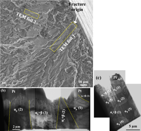
The fracture surface was investigated and smooth, near-planar crack initiating facets were found very slightly below the sample surface, Figure 1(a). The spatial and crystallographic orientation of these facets obtained by quantitative tilt fractography and EBSD are reported in Joseph et al.[27]. TEM foils were extracted from the two regions identified, at the crack nucleation site and, for comparison purposes, a region away in the fatigue crack growth region. The foils are shown in Figure 1(b-c) and the and two phase regions () regions marked. Each grain in the foils was tilted to at least three different beam directions and three different vectors under each beam condition to analyze the dislocations. The dislocations observed in the foils are discussed in the following sections.
3.1 Dislocation activities at the crack origin
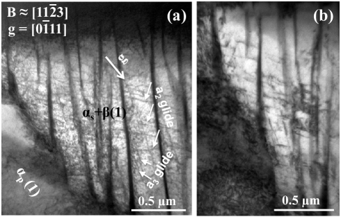
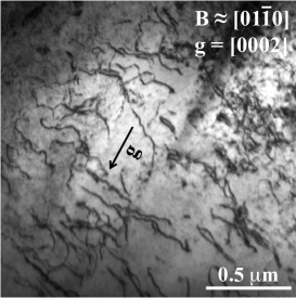
Foil 1 contained three different two phase regions and two regions, Figure 1(b). The dislocation activities in the two-phase (1) region under a two-beam condition with and are shown in Figure 2. The invisibility analysis shows that these are type dislocations with Burgers vector and in the plates. They are found to be of screw character, gliding on the (100) and (010) prism planes, respectively. Further, they are gliding on their respective planes without much interaction. The dislocations near the boundary with are shown in Figure 2b.
| Region | Types | Burgers vector and habit plane |
|---|---|---|
| Primary alpha grain | ||
| Slip bands 1-4 | (a/3)]( | |
| Long dislocation lines | (a/3)]( | |
| Random dislocation lines | (a/3)] | |
| Random dislocation lines | (a/3)] | |
| Two-phase region | ||
| glide | (a/3)]( | |
| glide | (a/3)]( |
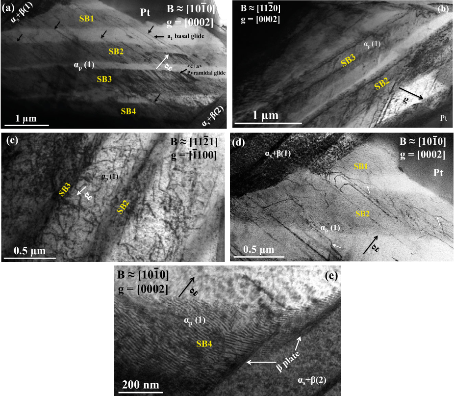
A high dislocation density was observed in initiating facet , Figure 3. Different illumination conditions are shown in each micrograph; intense planar pile-ups, long straight dislocations and random dislocation lines can be discerned. The dislocation bands (marked SB) are found to be of type with , having mixed character and gliding on the first order pyramidal plane (101), Figure 3a. The slip bands are around 350– in thickness, very much higher than classical pile-ups. The dislocations in this array are also dense and tightly packed. Further, each slip band is not a single pile-up but instead consists of a double ended pile-up, Figure 3b. The long straight dislocations indicated by black arrows in Figure 3a are found to be of type with Burgers vector having edge character gliding on the basal plane. The random dislocation lines in Figure 3c are found to be of type with .
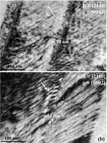
To investigate the nature of the dislocations in the pile-ups, the image displacement method [34] was used. This method is one of the useful dislocation image contrasts which determines whether a pair of dislocations are of same or opposite sign, by viewing them with opposite operating reflections, i.e., and . The dislocations in the double ended pile-ups were captured under two different ’s, and near , Figure 4. One dislocation in each pile-up which could be identified without any ambiguity in both the and conditions are shown by arrows. The separation between the pair of dislocations changes upon changing the sign of , which means that the dislocations are of opposite sign. There will be no change in separation when the dislocations are of same sign; therefore it is concluded that the dislocation on neighbouring slip planes in the double ended pile-ups are of opposite sign.
The interactions between the long dislocation lines and the other dislocations resulted in the formation of superjogs in the long dislocation lines, indicated by white arrows in Figure 3d. It can be noted that the mixed component of the long dislocation lines are found to pile-up in the boundary between (1) and , Figure 3d. It is also observed that the slip bands in this grain did not transfer across the boundary between the grain and the two phase region, even though they are intense and large. However, the slip bands were observed to shear the plate in the (3) region, Figure 3e.
Figure 5 shows the dislocations observed in , under the two beam condition with near . These dislocations are of type with , and are not observed to pile up on a particular plane. Similar to region + (1), + (2) also showed prismatic glide of type dislocations. Relatively few dislocations were observed in region + (3). For clarity, the dislocations in regions + (2) and + (3) will not be discussed further, but similar findings were obtained. The slip systems observed in foil 1 are summarised in Table 1.
3.2 Dislocation activities during fatigue crack growth, away from the nucleation site
This section discusses the dislocation activities in foil 2, Figure 1(c), which consists of many similarly oriented primary alpha grains and some two-phase regions.
3.2.1 Slip transfer across the grains
The slip activities across the five different grains in foil 2 are shown in Figure 6, which is a composite micrograph of bright field images taken when each grain is tilted to its two-beam condition individually. The crystallographic orientation of these grains normal to the loading direction was obtained by TKD of the TEM foil, Table 2. Grains 1 to 4 possessed almost similar inclinations of their -axes to the loading direction, with only grain having its -axis from the loading direction.
| Grain | Orientation of |
|---|---|
| -axis (degrees) | |
| 1 | 47.6 |
| 2 | 52.4 |
| 3 | 52.4 |
| 4 | 58.5 |
| 5 | 32.0 |
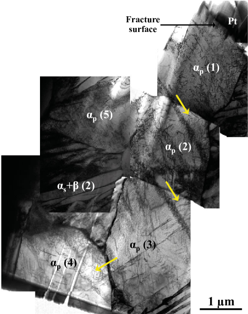
It was observed that the dislocations in the first four grains (1-4) piled-up, forming well-defined slip bands, and that those slip bands underwent slip transfer across the grain boundaries (indicated by arrows in Figure 6). Between grains 1/2 and 2/3, the piled up dislocations transferred across the boundary whereas between grains 3/4, just a single dislocation line was observed to transfer. In contrast, grain 5 shows neither pile up of dislocations nor slip transfer.
The slip activity in primary alpha grain (1) is shown in Figure 7, captured under a two-beam condition of and . The dislocations mainly piled-up on a particular slip plane and some dislocations are also observed between these pile-ups. The dislocations in the pile-up are of type and gliding on basal planes, marked as slip bands SB1, SB2 and SB3. The pile-up in SB1 was observed to be double ended. In addition to these dislocations on basal planes, the other type dislocations are found to glide in a random way, Figure 7b. Of the three slip bands observed in this grain, SB3 was found to transfer across the boundary, forming SB4 in primary alpha grain (2) .
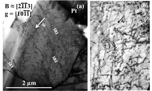
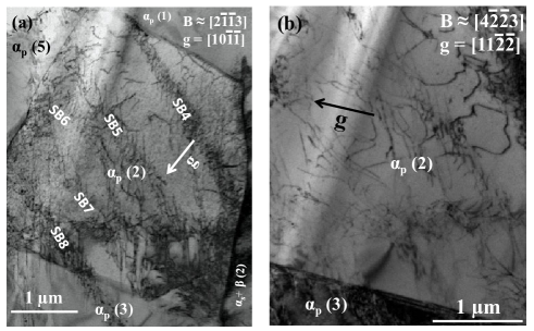
Figure 8 shows a high dislocation density in grain (2), mainly as pile-ups (SB4-SB8), with some random dislocations. The dislocations in this grain are shown under two different two beam conditions with and . This grain shares its boundary with grains 1, 3 and 5 and the two-phase region (2). All the slip bands observed in this grain were of basal slip character, as observed in grain 1. SB8 was found to transfer across the boundary, forming SB9 in grain 3. Slip transfer was not observed from grain 2 to grain 5 and the neighbouring two-phase region. In addition, some random dislocation lines were also observed, of type, Figure 8b.
The slip activity in (3) is shown in Figure 9, which is a bright field image captured in the two-beam condition with and . The various slip bands are marked. Slip bands 9, 10, 12 and 14 are basal and slip bands 11 and 13 are basal. Slip band 9 traversed the whole grain, indicating that it was the primarily activated deformation mode, while the other slip bands will be secondary slip activated after reaching a critical stress. There are other long dislocation lines in addition to the slip bands, of and type (dotted arrows). These dislocations were found to transfer the boundary between grains 3 and 4, where a thin ligament was observed between the grains, Figure 6. Thus this grain showed all the three types of dislocations, resulting in hexagonal networks of dislocations.
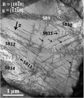
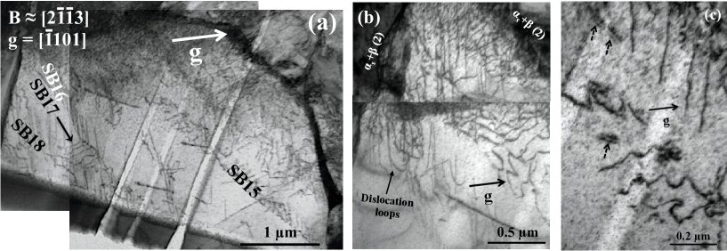
Figure 10 shows the slip activity in primary alpha grain (4), which was similarly found to deform mainly by planar slip. All the slip bands are basal except SB17 which was found to be of basal character. Many dislocation loops were observed near the boundary between this grain and the two-phase region (2), Figure 10b. Dislocation dipoles were also observed in this grain, shown by dotted arrows in Figure 10c. These dipoles are expected to form by encounters between dislocations of opposite sign. They are observed to be narrow screw dislocation dipoles, which are unstable and would be expected to decompose into invisible debris of near-atomic dimension.
In contrast, grain 5 did not show planar slip bands; instead homogeneous deformation was observed, Figure 11. Both and type dislocations were observed in this grain. The dislocations were of and type and were not observed on particular slip plane, Figure 11a. The dislocations were of type and were few in number and density, Figure 11b. The slip systems observed in the primary alpha grains of foil 2 are listed in Table 3
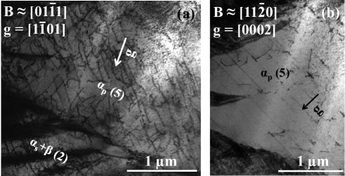
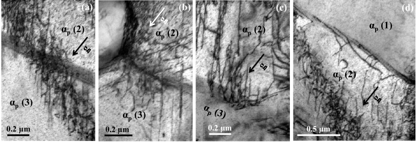
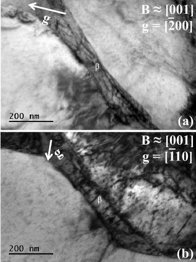
Figure 12 shows the various types of dislocation interactions near the boundaries (inclined in the foil; shadowed) of the primary alpha grains in foil 2. The interaction is mostly in the form of slip transfer of piled-up dislocations, Figure 12a, with some are slip transfer of dislocation groups, e.g. Figure 12b. At the grain 2/3 boundary, the impingement of dislocations has caused nucleation of dislocations in the same impinging grain 2, Figure 12c. This might be due to the generation of dislocation sources in the grain boundary by the impinging dislocations. Alternately, grain boundary blocking of dislocations can be observed in Figure 12d.
| Region | Types | Burgers vector and habit plane |
| Primary alpha grain | ||
| Slip bands 1-3 | (a/3)basal | |
| Random dislocation lines | (a/3)] | |
| Slip bands 4-8 | (a/3)basal | |
| Random dislocation lines | (a/3)basal | |
| Slip bands 9,10,12,14 | (a/3)basal | |
| Slip bands 11,13 | (a/3)basal | |
| Long dislocation lines | (a/3) and (a/3) | |
| Slip bands 15,16,18 | (a/3)basal | |
| Slip band 17 | (a/3)basal | |
| Random dislocation lines | (a/3),(a/3) and (a/3) | |
| Two-phase region | ||
| Dislocation loops | (a/3)basal | |
| Straight dislocations | (a/3)pyramidal | |
| Dislocation loops | (a/3)basal | |
| Pile-up | (a/3) | |
| Dislocation loops | (a/3)basal | |
| Dislocation network | (a/3) | |
| Dislocation network | (a/2) and (a/2){211} | |
| Straight dislocations | (a/2) |
3.2.2 Dislocation activities in two-phase region
Two phase region + (2) in foil 2 was selected for further study. The various plates and ligaments investigated are shown in Figure 13a, which is the pattern quality map obtained by TKD. The phase map and the orientation map are also shown in Figures 13b-c. The orientation relation between secondary alpha plates , and is shown in Figure 13d, which is the pole figure obtained from this two-phase region. The plane normal and the three directions of and plates are marked in the pole figures. The {110} plane normal and the and directions are marked in the pole figure. The procedure for identifying these plane normals and directions is discussed in [29]. It is found that the expected and Burgers’ orientation relation is obeyed [35].
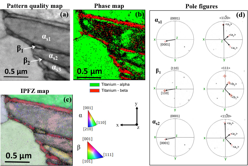
Figure 14 shows the slip activities in the plates, imaged in the two beam condition using the beam directions shown. Figures 14(a-b) are bright field images taken with near and ; was also in the diffraction condition due to its similar orientation to . The analysis shows that the straight dislocations in Figure 14a are of type with , having edge character and gliding on basal planes. The same type of dislocations can also be seen in plate , but this plate is slightly misoriented and is therefore darker in contrast. It can be observed that there is a one-to-one correspondence of these dislocations in these plates. A number of dislocation loops are observed to nucleate from the boundary, Figure 14b. These are found to be -type loops, gliding on basal planes. The nucleation of numerous -type dislocations in plate plate was observed in Figure 14c.
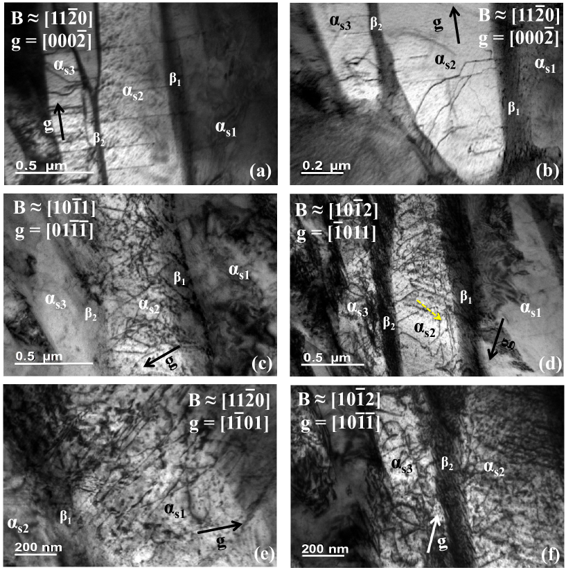
Figure 14d shows these -type dislocations and a pile-up of a small number of type dislocations near the boundary, which is shown by a dotted yellow arrow. In addition to these -type dislocations, some dislocations were observed in plate , Figure 14e, and a network of -type dislocations were observed in plate , Figure 14f. The dislocations in are of type, gliding on a first order pyramidal plane.
Both retained ligaments and show similar dislocation activities, so only ligament is shown here. Figure 15 shows bright field images under two beam conditions with and -vectors and . A network of dislocations are observed in this plate under , Figure 15a. Detailed analysis shows that these are and dislocations gliding on -type planes. In addition to these and dislocations, some (a/2)[010] dislocations were also observed with , Figure 15b. It is rare to observe this type of dislocation in Ti alloys. The slip systems observed in this two-phase region are summarised in Table 3.
4 Discussion
We will first discuss the dislocation behaviours found in both near-origin faceted fatigue crack growth and in the initiating grain, and compare to the observations made previously for similarly-oriented grains from the gauge section [27]. Then, we turn to examine slip transfer in the regions, before finally turning to the initiation grain to ask what is different about the dislocation configurations associated with crack nucleation.
4.1 Dislocation interactions in grains
Isolated dislocations are rarely observed in this alloy, indicating that dislocation groups or arrays are responsible for deformation. The two foils investigated exhibit strongly planar slip in the grains; due to the lack of forest hardening, this kind of planar slip leads to a low rate of work hardening. Planar slip in Al-containing hcp -Ti is believed to be a consequence of the short range ordering of Ti and Al atoms [36]. The passage of a single dislocation through -Ti3Al precipitates, possibly in pairs, makes it easier for subsequent dislocations to traverse the same plane, leading to pile-up in planar slip bands. The dense pile-ups observed indicate that, once the ordered precipitates / short range ordered regions are sheared, they no longer present a barrier to dislocation motion. Hence the local hardening rate for a slip plane is small once activity commences.
The pile-ups in of foil 1 near crack nucleation are dense, thick, double ended and non-classical, Figure 3 a and b. Following Tanaka and Mura [19], the intersection of this kind of large thickness pile-up with a microstructural boundary can trigger microcrack initiation. This is evidenced by the shearing of plates by the intense slip bands, Figure 3e. As these are not classical pile-ups, extensive run-back of dislocations contained within the arrays does not occur. This will then lead to high stress concentration on boundaries, due to the stress generated by these dislocations. The pile-ups in foil 2 are also dense and found to be double-ended, Figure 7. The motion of dislocations in opposite directions by multiple cross-slip events has been observed in -Ti during in-situ tensile testing [37], which provides a mechanism of formation of a double ended pile-up. We have previously observed this kind of dislocation multiplication by multiple cross-slip events, leading to double ended pile-ups, in TEM foils from the gauge section of this sample [27].
The various slip systems in grain (1) in foil 1 were not observed to interact strongly, except the jogging of isolated straight dislocation lines, Figure 3c. These are jogs in edge dislocations, which can move with the parent dislocation as the Burgers’ vector of the jogs lie in the slip plane of the parent dislocation. However, a higher Peierls stress is still required to move such jogged dislocations [38].
In foil 1, the grain possessing a double ended pile-up had no neighbouring grains, instead being bounded (in the section observed) by two-phase regions. Because of its higher critical resolved shear stress (CRSS), it can be difficult to activate pyramidal slip. It’s observation in the present case can be rationalised as being a consequence of constraint by the adjoining two phase regions. The pile-ups in this grain did not transfer across the boundary and it was also observed that the mixed components of the straight dislocations also piled-up, Figure 3d. The nature of these long dislocations with edge and mixed components suggests that these dislocation loops originated from the boundary. Thus, these boundaries act both as dislocation sources as well as providing resistance to slip transfer.
Many instances of slip transfer were observed between the similarly oriented grains in foil 2, Figure 6. It can be seen from this figure that both the dislocations in the pile-ups and single dislocations were found to transfer across the boundaries; pile-up transferring across the boundary in grain pairs 1/2 and 2/3, and single dislocation transfer between grains 3 and 4. This suggests that the large stress concentrations associated with pile-ups are not required for slip transfer across such similarly-oriented grains. Furthermore, such grain boundaries offer little resistance to dislocation motion. Among the many pile-ups, some traversed an entire grain, indicating that those are the primary slip activated. Subsequently, once stress is increased by a primary pile-up, secondary slip systems can be activated, Figure 9.
The observation of dislocation loops originating from the boundary in Figure 10b also supports that this boundary acted as a dislocation source. Among the five grains investigated in foil 2, only one, (5), was found to deform homogeneously; this grain’s -axis was oriented to the loading direction whereas all the other grains were inclined by , Table 2. in foil 1 also showed homogeneous deformation, Figure 5, with its -axis from the loading direction. This suggests that it is relatively rare to observe pile-ups in ‘hard-oriented’ grains, those with their -axis near the loading direction.
4.2 Dislocation interactions between and plates
From the dislocation structures observed in the two-phase regions, sec 3.2.2, the following mechanism is suggested for the deformation of the structure. The and plates follow the Burgers orientation relation, and , Fig. 13. The crystallographic relations bring one of the hcp close packed directions into near-coincidence with the bcc slip direction. A deviation from the Burgers’ orientation relation exists between individual and plates, with a between and , and a misorientation of observed between and [39, 40, 36]. The third -type slip direction in the plate does not have a closely aligned direction but is relatively closely aligned with . The misorientation between in the plate and in ligament is and the mismatch in their lengths is [30].
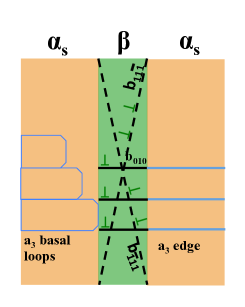
The schematic in Fig. 16 shows a possible mechanism of deformation in the two-phase region. Initially the dislocation loops nucleate from the boundary, gliding on basal planes. These loops then slip across the ligament to the neighbouring plate. This is expected since the slip easily traverses across the ligaments when they are very thin. Zhang et al [31] suggested that this slip transmission across the boundary is favoured by closely aligned slip plane normals in the two phases and the global Schmid factors are not appropriate to identify the local slip initiation in either phase.
The one-to-one correspondence between dislocations in all three plates investigated shows that these dislocations transferred across the . These are the edge components of the dislocation loops. During this slip transfer process, the plates are also sheared, resulting in -type dislocations. Since direction in plate has no closely matched slip direction in the plate, this relatively closely aligned slip is expected. The following reaction could occur during slip transmission across the boundary
| (1) |
where is a residual dislocation resulting from the misorientation and mismatch between the and dislocations. Such residual matrix dislocations can be observed near the boundary, Figure 14d. The transmission of dislocations into a plate requires higher stresses since the direction in the doesn’t have a closely aligned direction in the . However, the high interfacial stress at the interface might have caused this transmission. Further, the slip strength of plates was found to be of the same order as that of basal slip in plates which suggest that the plates may not act as a significant barrier for slip transmission [31].
Glide of such dislocations is rarely reported since the mobility of dislocations are much lower than that of the favoured dislocations. type slip activity has been reported in some bcc metals, e.g. in lithium [41] and niobium [42]. Furthermore, Savage et al [30] observed this dislocations in colony-structured Ti-6242 alloy after room temperature compression. Such a dislocation in the will then transfer into an dislocation in the next plate as
| (2) |
The two possibilities for the existence of these dislocations are either (i) that the intersection of and dislocations might have resulted in the formation of this dislocation, as described in Nb [43], or (ii) they could result from the direct slip transmission of dislocations in to dislocations in . The one-to-one correspondence between the dislocations in and dislocations in the supports the second mechanism.
The network of and dislocations observed in the plate we then expect to result from the dissociation of these dislocations into and dislocations
| (3) |
This decomposition is favored under high stresses due to the much higher mobility of and dislocations than dislocations[30]; the high stresses will arise from the applied shear stress and the interfacial stresses naturally present between the phases as a result of precipitation and cool-down from the formation temperature.
Thus the plates do not appear to form an impenetrable barrier to slip as observed in [31]. An another important observation was made in the work of Zhang et al [31] where the plates were found to show the strongest rate sensitivity, which is important in rate dependent deformation such as fatigue with a load hold.
4.3 Crack nucleation mechanism
Generally, it is believed that fatigue crack initiation in Ti alloys occurs by facet formation [44, 45, 46, 47, 48, 49, 50] and that the facets correspond to grains. Our fractographic analysis also showed facet formation near the crack initiation site with the appearance of grains. However, after FIB foil extraction, some of the facets are found to be two phase regions. This is possible when slip in plates transfers across the along the closely aligned directions, i.e. and directions in into and in the retained . In that case, the two phase region can be featureless, with the appearance of a smooth facet. This kind of facet with an underlying two phase microstructure has on occasion been observed, e.g by Pilchak et al. [51] during the fatigue of fully lamellar Ti-6Al-4V.
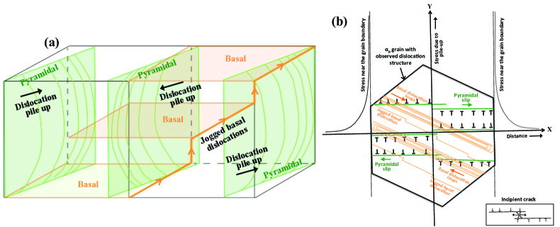
Based on the observations in foil 1 near the fatigue crack initiation, the following crack nucleation mechanism is proposed. Near the crack initiation, substantial dislocation activity was observed in grain , which is adjacent to a transformed region on either side, Figure 3a. The sketch in Figure 17a shows the overall dislocation activity in this grain. The dislocations were arranged as a double-ended pile-up containing dislocations of opposite sign in the successive (stacked) pyramidal planes. This suggests that during the first half of the loading cycle, pile-up of dislocations with a positive sign occurs on the first slip plane. Then, reverse plasticity in the second half cycle causes pile-up of dislocations of negative sign on successive planes close to the first slip plane. It is also possible for the dislocations in the first plane to reverse completely during the second half of the cycle. If such complete reversal of piled-up dislocations in the first plane occurs, then there is no accumulation of dislocations as a double ended pile-up [19]. Incomplete reversibility of dislocation motion could be realized if the lattice friction stress against dislocation motion is higher in the reverse direction than in the forward direction [19]. This could be rationalised as follows.
The back stress developed by these dislocations is negative in the vicinity of pileup in the first plane, which would cause plastic flow in the reverse direction in the neighbouring plane during subsequent reverse loading [19]. The pile-up of negative dislocations on the second plane then causes a positive back stress on the first plane. This back stress enhances the pile-up of positive dislocations during the next stage of forward loading. As the number of cycles increases the number of dislocations in each slip plane as well as the number of piled-up planes increases, hence resulting in the formation of a double ended pile-up, similar to the dislocation distribution near a crack subjected to a shear stress [52, 19, 53]. This kind of pile-up is possible only when the dislocation sources are located very close to each other, because for an isolated dislocation source, the dislocation motion on a plane becomes reversible as there is no back stress produced by the dislocations on a neighbouring plane. Therefore, the reversibility or otherwise of dislocation motion will depend on the statistical distribution of dislocation sources.
An alternative explanation for the formation of the double ended pile-up might be the occurrence of multiple cross-slip events, as observed in the grains from the gauge section of the same sample [27]. But, the dislocation debris and loops that would be produced by such cross-slip events were not observed in this grain, suggesting that instead that the irreversibility mechanism outlined above was responsible for the double ended pile-up in this grain.
The crack might then nucleate from the accumulated dislocation pile-ups in the following ways: (i) along the slip band [54, 10]; (ii) from the grain boundary or two phase region boundary where the slip bands intersect [19]; or (iii) the stress concentration due to this pile-up can nucleate a crack in the neighbouring grain due to load shedding [55, 56, 57]. The first two cases were not observed in the present study since the crack was not observed along the direction of slip bands or along the grain or two-phase region boundary. Case (iii) is also not possible in this case as this grain with dislocation pile-ups did not possess adjacent alpha grains and is bounded by two phase regions. Further, these two phase regions are found to offer high resistance for the slip transfer of piled-up dislocations from grains [27].
Instead, we suggest that the embryonic crack might have nucleated from this double ended pile-up as follows. The stress field in this case would be the sum of applied stress and the internal stresses due to the dislocation pile-ups on successive slip planes. In addition, the mixed components of the basal dislocation loops were also found to pile up near the boundary (Figure 3b), causing further stress intensification.
The microplasticity produced by the slip bands within individual grains has been considered as an important parameter in microstructure sensitive computational methods by D.L. McDowell et al. [58, 59, 60]. It is found to be a key driving force for fatigue crack nucleation and microstructurally small fatigue crack growth. The accumulated plastic strain can be used as a fatigue indicator parameter (FIP) for crack formation. This parameter was found to be an good indicator for predicting fatigue crack nucleation in both low cycle and high cycle fatigue.
The stress distribution due to this double ended pile-up together with the dislocation structures in the grain is shown in the schematic, Figure 17b. The stress intensification takes place near the tips of the pile-up. A large tensile stress is built up between the two planes of opposite sign dislocations in the pile-up, nucleating the facet. The tensile stress at half the distance between the two slip planes is given as [19]:
| (4) |
where 2a is the grain size, n is the number of stress cycles, is the cyclic shear stress applied to the grain, is the lattice friction stress and is the slip plane interplanar spacing.
The tensile stress would split the atomic planes along the dislocation lines [61], inset of Figure 17b. This can be observed in Figure 3a – the crack grew along the dislocation line direction. Therefore the large tensile stress resulting from the double ended pile-up appears to be the mechanism responsible for crack nucleation in the grain. From the TEM foil, it was observed that the fracture plane is found to be oriented 5– from the basal plane. This near-basal plane cracking rather than true basal plane cracking might be a consequence of the observed jogging of the basal dislocations.
A new microstructural level critical stored energy density criterion proposed by Wan et al. [62] argued that the statistically stored and geometrically necessary dislocations played a role in developing highly localized stress states, capable of causing localized cleavage. The critical plane criterion with strain based damage parameter [63] showed that the damage was controlled by the shear strain on the crystallographic slip plane and the fatigue crack growth was assisted by the normal strains on the same planes.
The fatigue indicator parameter (FIP) suggested by C.P. Przybyla et al. [60] is formulated to capture the effect of crystallographic orientation of primary grains on fatigue crack formation in Ti alloys. By design of the parameter, grains oriented favourably for slip on pyramidal show an extreme value of this FIP, similar to the present observation of crack nucleation from a primary grain with a double ended pile-up in pyramidal planes.
5 Conclusions
The dislocation structures associated with the fatigue crack initiation site in aged bimodal Ti6242Si subjected to low cycle fatigue were examined, and compared to those previously found in the gauge and to those found in grains associated with crack growth. The following conclusions are drawn.
1. The alloy mainly deforms by cooperative movement of a large number of dislocations in the primary alpha grains, which predominantly deform by planar slip; interaction between the different operating slip systems is relatively rare. These pile-ups are found to be localized within the grain when the grain shares its boundary with two-phase regions or dissimilarly oriented grains; the slip bands transfer across the boundary when the grain has similarly oriented neighbour. The boundary between the primary alpha grain and a two phase region acts both as a dislocation source and as a barrier to slip transfer between primary alpha grains.
2. Dislocations in two phase regions were observed to nucleate from the / boundaries as dislocation loops. A number of basal loops were observed on basal planes in the plates; the edge component of these loops were found to transfer across the retained ligaments. As the slip direction in the plates doesn’t have a closely aligned slip direction in the , direct transmission needs higher stress. These dislocations become dislocations in the and subsequently decompose into a pair of mobile dislocations, observed as dislocation networks in the .
3. The high dislocation density observed in one of the primary alpha grains nearest the initiation site suggests that crack nucleation occurred from this grain. pyramidal slip was observed in this grain, which may be a consequence of the constraint imposed by the two phase regions on the either side of this grain, as well as the applied stress. Dislocations were observed to be piled up on both the ends of the grain, with positive and negative dislocations observed on neighbouring slip planes. Such structures can result from the incomplete reversibility of dislocation motion due to a slightly higher friction stress in the reverse direction than in the forward direction. This kind of double ended pile-up results in a large tensile stress between the two planes, providing a mechanism of crack initiation by plane splitting along the dislocation lines. The observation of superjogs on the basal dislocations provides a rationale for why such cracks nucleate near rather than on the basal plane.
Acknowledgements
The authors wish to acknowledge the contribution and useful discussions with Prof D Rugg at Rolls-Royce plc, Prof FPE Dunne and Dr TB Britton at Imperial, and Prof AJ Wilkinson in Oxford, with whom we are funded under the Hexmat EPSRC programme grant EP/K034332/1.
References
References
- [1] WH Kim and C Laird. Crack nucleation and stage I propagation in high strain fatigue–ii. mechanism. Acta Metallurgica, 26(5):789–799, 1978.
- [2] D Luquiau, X Feaugas, and M Clavel. Cyclic softening of the Ti-10V-2Fe-3Al titanium alloy. Materials Science and Engineering: A, 224(1-2):146–156, 1997.
- [3] KS Chan, CC Wojcik, and DA Koss. Deformation of an alloy with a lamellar microstructure: experimental behavior of individual widmanstatten colonies of an - titanium alloy. Metallurgical and Materials Transactions A, 12(11):1899–1907, 1981.
- [4] L Wagner and G Lutjering. Microstructural influence on propagation behavior of short cracks in an (alpha+ beta) titanium alloy. Z. Metallkd., 78(5):369–375, 1987.
- [5] RR Boyer and J Hall. Microstructure-property relationships in titanium alloys- critical review. Titanium’92: Science and technology, pages 77–88, 1993.
- [6] FPE Dunne, AJ Wilkinson, and R Allen. Experimental and computational studies of low cycle fatigue crack nucleation in a polycrystal. International Journal of Plasticity, 23(2):273–295, 2007.
- [7] C Tan, X Li, Q Sun, L Xiao, Y Zhao, and J Sun. Effect of -phase morphology on low-cycle fatigue behavior of TC21 alloy. International Journal of Fatigue, 75:1–9, 2015.
- [8] MA Bao-Tong and C Laird. Overview of fatigue behavior in copper single crystals—-i. surface morphology and stage I crack initiation sites for tests at constant strain amplitude. Acta Metallurgica, 37(2):325–336, 1989.
- [9] ZS Basinski and SJ Basinski. Fundamental aspects of low amplitude cyclic deformation in face-centred cubic crystals. Progress in Materials Science, 36:89–148, 1992.
- [10] J Ahmed, AJ Wilkinson, and SG Roberts. Electron channelling contrast imaging characterization of dislocation structures associated with extrusion and intrusion systems and fatigue cracks in copper single crystals. Philosophical Magazine A, 81(6):1473–1488, 2001.
- [11] J Polák and J Man. Experimental evidence and physical models of fatigue crack initiation. International Journal of Fatigue, 91:294–303, 2016.
- [12] SJ Basinski, ZS Basinski, and A Howie. Early stages of fatigue in copper single crystals. Philosophical Magazine, 19(161):899–924, 1969.
- [13] U Essmann and H Mughrabi. Annihilation of dislocations during tensile and cyclic deformation and limits of dislocation densities. Philosophical Magazine A, 40(6):731–756, 1979.
- [14] C Laird, P Charsley, and H Mughrabi. Low energy dislocation structures produced by cyclic deformation. Materials Science and engineering, 81:433–450, 1986.
- [15] AS Beranger, X Feaugas, and M Clavel. Low cycle fatigue behavior of an + titanium alloy: Ti6246. Materials Science and Engineering: A, 172(1-2):31–41, 1993.
- [16] OB Pedersen and AT Winter. Cyclic hardening and slip localization in single slip oriented copper crystals. Physica Status Solidi (a), 149(1):281–296, 1995.
- [17] NF Mott. A theory of the origin of fatigue cracks. Acta Metallurgica, 6(3):195–197, 1958.
- [18] U Essmann, U Gösele, and H Mughrabi. A model of extrusions and intrusions in fatigued metals i. point-defect production and the growth of extrusions. Philosophical Magazine A, 44(2):405–426, 1981.
- [19] K Tanaka and T Mura. A dislocation model for fatigue crack initiation. Journal of Applied Mechanics(Transactions of the ASME), 48(1):97–103, 1981.
- [20] MD Sangid, HJ Maier, and H Sehitoglu. A physically based fatigue model for prediction of crack initiation from persistent slip bands in polycrystals. Acta Materialia, 59(1):328–341, 2011.
- [21] N Singh, Gouthama, and V Singh. Low cycle fatigue behavior of Ti alloy IMI 834 at room temperature. Materials Science and Engineering: A, 325(1):324–332, 2002.
- [22] L Xiao and Y Umakoshi. Cyclic deformation behaviour and dislocation structure of Ti-5 at.% Al single crystals oriented for double prism slip. Philosophical Magazine A, 82(12):2379–2396, 2002.
- [23] N Singh, Gouthama, and V Singh. Low cycle fatigue behaviour of Ti alloy Timetal 834 at 873K. International Journal of Fatigue, 29(5):843–851, 2007.
- [24] S Li, B Xiong, S Hui, W Ye, and Y Yu. Comparison of the fatigue and fracture of Ti–6Al–2Zr–1Mo–1V with lamellar and bimodal microstructures. Materials Science and Engineering: A, 460:140–145, 2007.
- [25] J Huang, Z Wang, and K Xue. Cyclic deformation response and micromechanisms of Ti alloy Ti–5Al–5V–5Mo–3Cr–0.5Fe. Materials Science and Engineering: A, 528(29):8723–8732, 2011.
- [26] GQ Wu, CL Shi, W Sha, AX Sha, and HR Jiang. Effect of microstructure on the fatigue properties of Ti–6Al–4V titanium alloys. Materials & Design, 46:668–674, 2013.
- [27] S Joseph, I Bantounas, TC Lindley, and D Dye. Slip transfer and deformation structures resulting from the low cycle fatigue of near-alpha titanium alloy Ti-6242Si. International Journal of Plasticity,100:90–103, 2018.
- [28] D Bhattacharyya, and GB Viswanathan, and Robb Denkenberger, and D Furrer, and Hamish L Fraser. The role of crystallographic and geometrical relationships between and phases in an / titanium alloy. Acta Materialia,51(16):4679–4691, 2003.
- [29] V Tong, S Joseph, AK Ackerman, D Dye, and TB Britton. Using transmission Kikuchi diffraction to characterise variants in an + titanium alloy. Journal of Microscopy, 2017.
- [30] MF Savage, J Tatalovich, and MJ Mills. Anisotropy in the room-temperature deformation of – colonies in titanium alloys: role of the – interface. Philosophical Magazine, 84(11):1127–1154, 2004.
- [31] Z Zhang, T-S Jun, TB Britton, and FPE Dunne, Determination of Ti-6242 and slip properties using micro-pillar test and computational crystal plasticity. Journal of the Mechanics and Physics of Solids, 95:393–410, 2016.
- [32] James R Seal, Martin A Crimp, Thomas R Bieler, Carl J Boehlert. Analysis of slip transfer and deformation behavior across the / interface in Ti–5Al–2.5 Sn (wt.%) with an equiaxed microstructure. Materials Science and Engineering: A, 552:61–68, 2012.
- [33] CJ Szczepanski, SK Jha, PA Shade, R Wheeler, and JM Larsen. Demonstration of an in situ microscale fatigue testing technique on a titanium alloy. International Journal of Fatigue, 57:131–139, 2013.
- [34] JH Richardson. Systematic Materials Analysis, volume 4. Elsevier, 2012.
- [35] WG Burgers. On the process of transition of the cubic-body-centered modification into the hexagonal-close-packed modification of zirconium. Physica, 1(7-12):561–586, 1934.
- [36] MF Savage, T Neeraj, and MJ Mills. Observations of room-temperature creep recovery in titanium alloys. Metallurgical and Materials Transactions A, 33(3):891–898, 2002.
- [37] J Kacher and IM Robertson. In situ TEM characterisation of dislocation interactions in -titanium. Philosophical Magazine, 96(14):1437–1447, 2016.
- [38] P Gumbsch and R Pippan. Multiscale modelling of plasticity and fracture by means of dislocation mechanics, volume 522. Springer Science & Business Media, 2011.
- [39] S Suri, GB Viswanathan, T Neeraj, D-H Hou, and MJ Mills. Room temperature deformation and mechanisms of slip transmission in oriented single-colony crystals of an / titanium alloy. Acta Materialia, 47(3):1019–1034, 1999.
- [40] MF Savage, J Tatalovich, M Zupan, KJ Hemker, and MJ Mills. Deformation mechanisms and microtensile behavior of single colony Ti–6242Si. Materials Science and Engineering: A, 319:398–403, 2001.
- [41] I Gorgas. Slip line investigations in lithium at 162K. Scripta Metallurgica, 20(1):113–117, 1986.
- [42] CN Reid, A Gilbert, and GT Hahn. Twinning, slip and catastrophic flow in niobium. Acta Metallurgica, 14(8):975–983, 1966.
- [43] F Louchet and LP Kubin. Dislocation substructures in the anomalous slip plane of single crystal niobium strained at 50K. Acta Metallurgica, 23(1):17–21, 1975.
- [44] V Sinha, MJ Mills, J Cv Williams, and JE Spowart. Observations on the faceted initiation site in the dwell-fatigue tested Ti-6242 alloy: crystallographic orientation and size effects. Metallurgical and Materials Transactions A, 37(5):1507–1518, 2006.
- [45] MR Bache, WJ Evans, and HM Davies. Electron back scattered diffraction (EBSD) analysis of quasi-cleavage and hydrogen induced fractures under cyclic and dwell loading in titanium alloys. Journal of Materials Science, 32(13):3435–3442, 1997.
- [46] WJ Evans. Dwell sensitive fatigue response of titanium alloys for power plant applications. Journal of Engineering for Gas Turbines and Power 125(1), 241-245, 2003.
- [47] K Kirane and S Ghosh. A cold dwell fatigue crack nucleation criterion for polycrystalline Ti-6242 using grain-level crystal plasticity Fe model. International Journal of Fatigue, 30(12):2127–2139, 2008.
- [48] FPE Dunne and D Rugg. On the mechanisms of fatigue facet nucleation in titanium alloys. Fatigue & Fracture of Engineering Materials & Structures, 31(11):949–958, 2008.
- [49] M Anahid, MK Samal, and S Ghosh. Dwell fatigue crack nucleation model based on crystal plasticity finite element simulations of polycrystalline titanium alloys. Journal of the Mechanics and Physics of Solids, 59(10):2157–2176, 2011.
- [50] Z Zheng, DS Balint, and FPE Dunne. Dwell fatigue in two Ti alloys: an integrated crystal plasticity and discrete dislocation study. Journal of the Mechanics and Physics of Solids, 96:411–427, 2016.
- [51] AL Pilchak, REA Williams, and JC Williams. Crystallography of fatigue crack initiation and growth in fully lamellar Ti-6Al-4V. Metallurgical and Materials Transactions A, 41(1):106, 2010.
- [52] BA Bilby and JD Eshelby. Dislocations and the theory of fracture; In Fracture—-an advanced treatise (ed. H Liebowitz), Volume 1, pp99–182, New York: Academic Press, 1968.
- [53] JP Hirth, J Lothe. Theory of dislocations. Wiley, New York, page 270, 1982.
- [54] MR Lin, ME Fine, and T Mura. Fatigue crack initiation on slip bands: theory and experiment. Acta Metallurgica, 34(4):619–628, 1986.
- [55] AN Stroh. The formation of cracks as a result of plastic flow. In Proceedings of the Royal Society of London A, 223:404–414. The Royal Society, 1954.
- [56] WJ Evans and MR Bache. Dwell-sensitive fatigue under biaxial loads in the near-alpha titanium alloy IMI685. International Journal of Fatigue, 16(7):443–452, 1994.
- [57] TB Britton and AJ Wilkinson. Stress fields and geometrically necessary dislocation density distributions near the head of a blocked slip band. Acta Materialia, 60(16):5773–5782, 2012.
- [58] DL McDowell and FPE Dunne. Microstructure-sensitive computational modeling of fatigue crack formation. International journal of fatigue, 32(9): 1521–1542, 2010.
- [59] Craig P Przybyla, and Craig P McDowell. Simulated microstructure-sensitive extreme value probabilities for high cycle fatigue of duplex Ti–6Al–4V. International Journal of Plasticity, 27(12): 1871–1895, 2011.
- [60] Craig P Przybyla, William D Musinski, Gustavo M Castelluccio and David L McDowell. Microstructure-sensitive HCF and VHCF simulations. International Journal of Fatigue, 57:9–27, 2013.
- [61] FE Fujita. Dislocation theory of fracture of crystals. Acta Metallurgica, 6(8):543–551, 1958.
- [62] VVC Wan, DW MacLachlan, and FPE Dunne. A stored energy criterion for fatigue crack nucleation in polycrystals. International Journal of Fatigue, 68:90–102, 2014.
- [63] FA Kandil FA and MW Brown. Biaxial low cycle fatigue of 316 stainless steel at elevated temperatures. International conference on mechanical behaviour and nuclear applications of stainless steel at elevated temperatures. Metals Society (London), 203-–209, 1982.