MHD simulation of prominence eruption
Abstract
We carry out magnetohydrodynamic (MHD) simulations of the quasi-static evolution and eruption of a twisted coronal flux rope under a coronal streamer built up by an imposed flux emergence at the lower boundary. The MHD model incorporates a simple empirical coronal heating, optically thin radiative cooling, and field aligned thermal conduction, and thus allows the formation of prominence condensations. We find that during the quasi-static evolution, prominence/filament condensations of an elongated, sigmoid morphology form in the dips of the significantly twisted field lines of the emerged flux rope due to run-away radiative cooling. A prominence cavity also forms surrounding the prominence, which is best observed above the limb with the line-of-sight nearly along the length of the flux rope, as shown by synthetic SDO/AIA EUV images. The magnetic field supporting the prominence is significantly non-force-free despite the low plasma-. By comparing with a simulation that suppresses prominence formation, we find that the prominence weight is dynamically important and can suppress the onset of the kink instability and hold the flux rope in equilibrium for a significantly long time, until draining of the prominence plasma develops and lightens the prominence weight. The flux rope eventually develops the kink instability and erupts, producing a prominence eruption. The synthetic AIA 304 Å images show that the prominence is lifted up into an erupting loop, exhibiting helical features along the loop and substantial draining along the loop legs, as often seen in observations.
1 Introduction
Observations have shown a close association between prominence/filament eruptions and coronal mass ejections (CMEs) (e.g. Munro et al., 1979; Webb & Hundhausen, 1987). This indicates that understanding the hosting magnetic field structures capable of supporting the prominence/filament are important for understanding the origin of CMEs. One type of model for the hosting magnetic structure is a magnetic flux rope with helical field lines twisting about its central axis, with the cool and dense prominence plasma suspended in the dips of the field lines in the much hotter and rarefied corona (e.g. Low, 2001; Gibson, 2015). Many MHD simulations have been carried out to study the mechanisms, such as the helical kink instability and the torus instability, for the destabilization and eruption of a coronal flux rope and successfully achieved the eruptive behavior (e.g. Török & Kliem, 2005, 2007; Török et al., 2011; Aulanier et al., 2010; Fan & Gibson, 2007; Fan, 2010, 2012; Chatterjee & Fan, 2013; Amari et al., 2014). These simulations have generally used highly simplified thermodynamics, e.g. zero-plasma , isothermal, or a polytropic gas with lowered adiabatic index , without the possibility for the formation of the cool prominence/filament condensations. Thus the possible dynamic role the prominence mass plays on the stability and eruptive properties of the coronal flux ropes (e.g. Low, 1996) have not been well modeled in MHD simulations of CMEs, despite observational indications of its importance (e.g. Jenkins et al., 2018).
Increasingly, 3D MHD simulations of CMEs and CME source regions are conducted with more realistic treatment of the thermodynamics to allow for a more direct comparison with coronal multi-wavelength observations (e.g. Downs et al., 2012; Török et al., 2018) and to model the formation of prominences/filaments (e.g. Xia et al., 2014; Xia & Keppens, 2016; Fan, 2017). Xia et al. (2014) and Xia & Keppens (2016) have carried out the first 3D MHD simulations of the formation of a prominence in a stable equilibrium coronal flux rope, by incorporating the important non-adiabatic effects of an empirical coronal heating, optically thin radiative losses, and field aligned thermal conduction. They have also used an adaptive grid to resolve the fine-scale internal dynamics of the prominence. Their model obtained a prominence-cavity system with the prominence containing fine-scale, highly dynamic fragments, which reproduced many observed features seen in SDO/AIA observations. Recently, Fan (2017) has carried out a first 3D MHD simulation of a prominence-carrying coronal flux rope that transitions from quasi-equilibrium to eruption, with the thermodynamics treatment incorporating the non-adiabatic effects of a simple empirical coronal heating, optically thin radiative losses, and field-aligned thermal conduction. In that simulation a significantly twisted, long coronal flux rope builds up under a pre-existing coronal streamer by an imposed flux emergence at the lower boundary. It is found that during the quasi-static phase of the evolution of the emerged flux rope, cool prominence condensations form in the dips of the twisted field lines due to in-situ radiative instability driven by the optically thin radiative cooling. Subsequently, the flux rope erupts as it develops the kink instability, and a prominence eruption is produced with substantial draining of the prominence plasma. That simulation also shows that once the prominence is formed, the magnetic field supporting the prominence becomes significantly non-force-free, despite the fact that the entire flux rope has low plasma-. This suggests that the weight of the prominence mass may be dynamically important.
In this paper we use the same numerical model described in Fan (2017) to carry out further simulations of the evolution of a significantly twisted coronal flux rope under a coronal streamer built up by an imposed flux emergence at the lower boundary. By changing the specification of the lower boundary coronal base pressure, we obtained the formation of a more massive and extended prominence with more dips forming prominence condensations in the emerged flux rope. As a result we also found a more continuous and extended low density region surrounding the elongated prominence/filament in the flux rope, producing a prominence-cavity system in the synthetic AIA EUV images with the flux rope observed above the limb viewed along a line-of-sight nearly along the length of the flux rope. By comparing with a corresponding simulation where we suppress the formation of prominence condensations, we found that the weight of the prominence mass can suppress or delay the onset of the kink instability of an otherwise nearly force-free flux rope, until significant draining of the prominence develops.
2 Model Description
The numerical simulations of this work use the “Magnetic Flux Eruption” (MFE) code to solve the same set of semi-relativistic MHD equations in spherical geometry as described in detail in Fan (2017, hereafter F17). The thermodynamics treatment of the simulations explicitly takes into account the non-adiabatic effects of an empirical coronal heating (that depends on height only), optically thin radiative cooling, and field aligned heat conduction. The simulation domain is in the corona, ignoring the photosphere and chromosphere layers, with the lower boundary temperature and density set at the base of the corona. The detailed simulation setups, including the equations solved, the numerical algorithms used, and the initial state and the boundary conditions, are all as described in F17, and the readers are referred to section 2 and section 3.1 in that paper for these descriptions. The specific changes made for the simulations of this paper are described below. All simulations in this paper use the set up (in regard to the simulation domain, initialization of the initial helmet streamer solution, and the boundary conditions) of the “WS-L” case described in F17 (where “WS-L” denotes Wide Streamer and Long curvature radius of the driving emerging torus in F17). As a brief summary of the set up, we first initialize a 2D quasi-steady solution of a coronal steamer with an ambient solar wind in a spherical wedge domain with , , and , where is the solar radius. Into the dome of the streamer we drive the slow emergence of a portion of a twisted magnetic torus at the lower boundary (see equations (19)-(22) and associated description in F17), so that a long twisted flux rope is built up quasi-statically under the steamer, and we study its resulting dynamic evolution in the corona. One change made for the simulations in this paper is that we have used different values for the proportionality parameter in equation (18) in F17. That equation determines the (varying) lower boundary pressure in response to the downward heat conduction flux, to crudely represent the effect of chromospheric evaporation as described in F17. We have carried out two simulations in this paper, one develops prominence condensations (hereafter referred to as the “PROM” case), and the other does not (hereafter referred to as the “non-PROM” case) for comparison. For the PROM case, we have used a value that is increased to about 1.5 times the value used in F17. This increases the coronal base pressure at the lower boundary given the same downward heat condition, and it results in the formation of a more massive and extended prominence in the emerged coronal flux rope compared to the WS-L case in F17, as described in section 3 below. For the non-PROM case, we have used the same value as that in F17. But we have modified the radiative loss function ( in F17) as shown in the red dashed curve in Figure 1 to reduce cooling for temperature below K compared to that used for the PROM case (black curve, which is the same as the one used in WS-L case in F17).

We have also enhanced thermal conduction for below K in the non-PROM case: for the thermal conduction heat flux given by equation (10) in F17, the thermal conductivity is set to a constant value of for . With these changes in the non-PROM case we are able to suppress the development of runaway radiative cooling and prevent the formation of prominence condensations with temperatures below K. Finally, the field strength for the emerging magnetic torus used for driving the lower boundary flux emergence, in Table 1 of F17, is set to 103 G for both the PROM and non-PROM simulations (instead of the 100 G for the WS-L case in F17).
3 Simulation results
3.1 Simulations with and without the prominence: the dynamical effect of the prominence mass
For the initial state of the PROM simulation, we first initialize a 2D quasi-steady solution of a coronal streamer with a background solar wind, following the procedure described in section 3.1 of F17 for setting up the WS (wide streamer) solution. The relaxed initial streamer solution is shown in Figure 2.
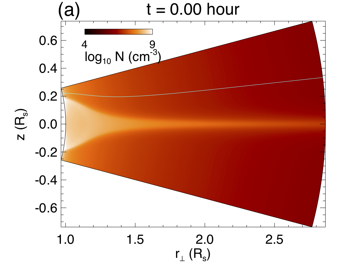
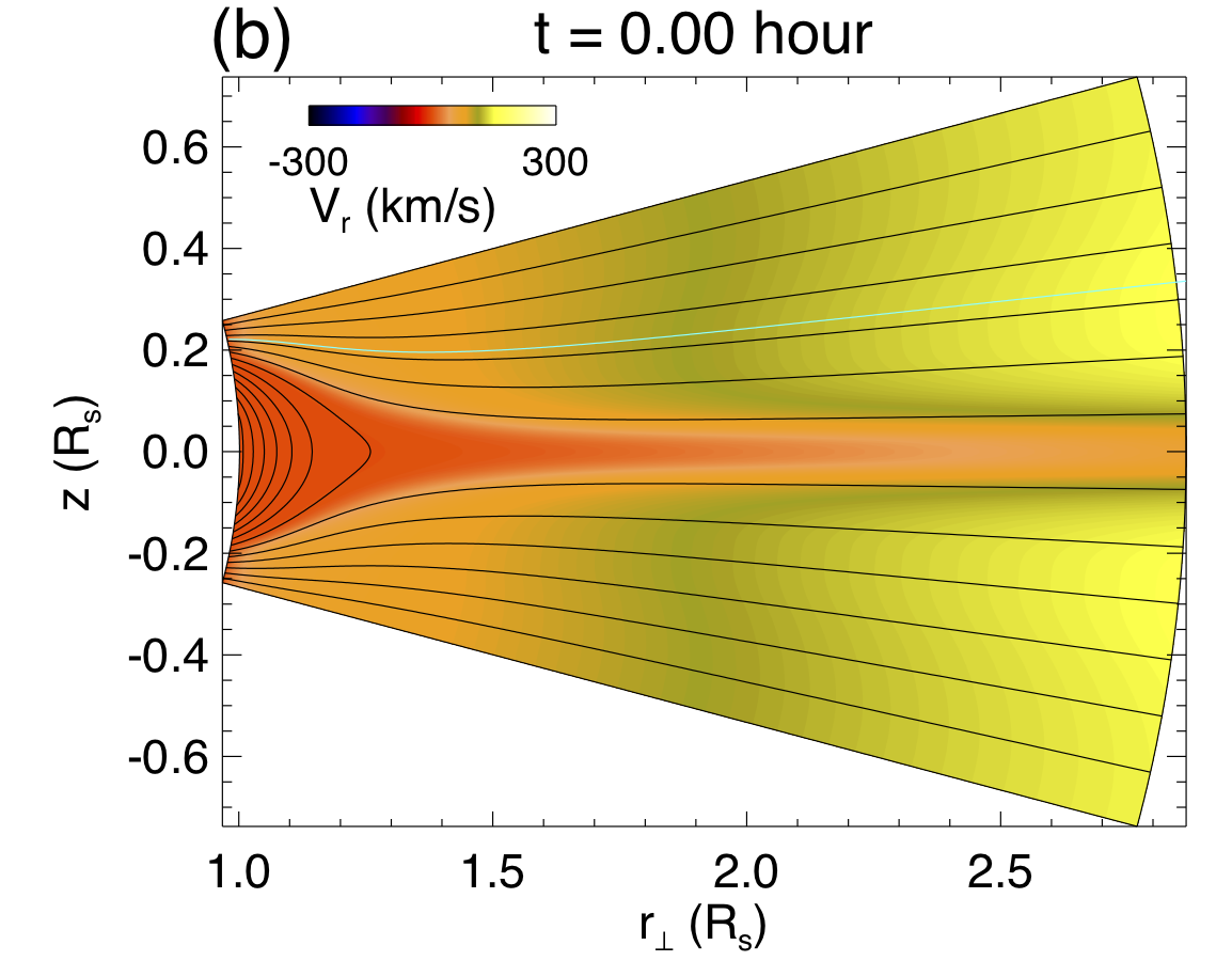
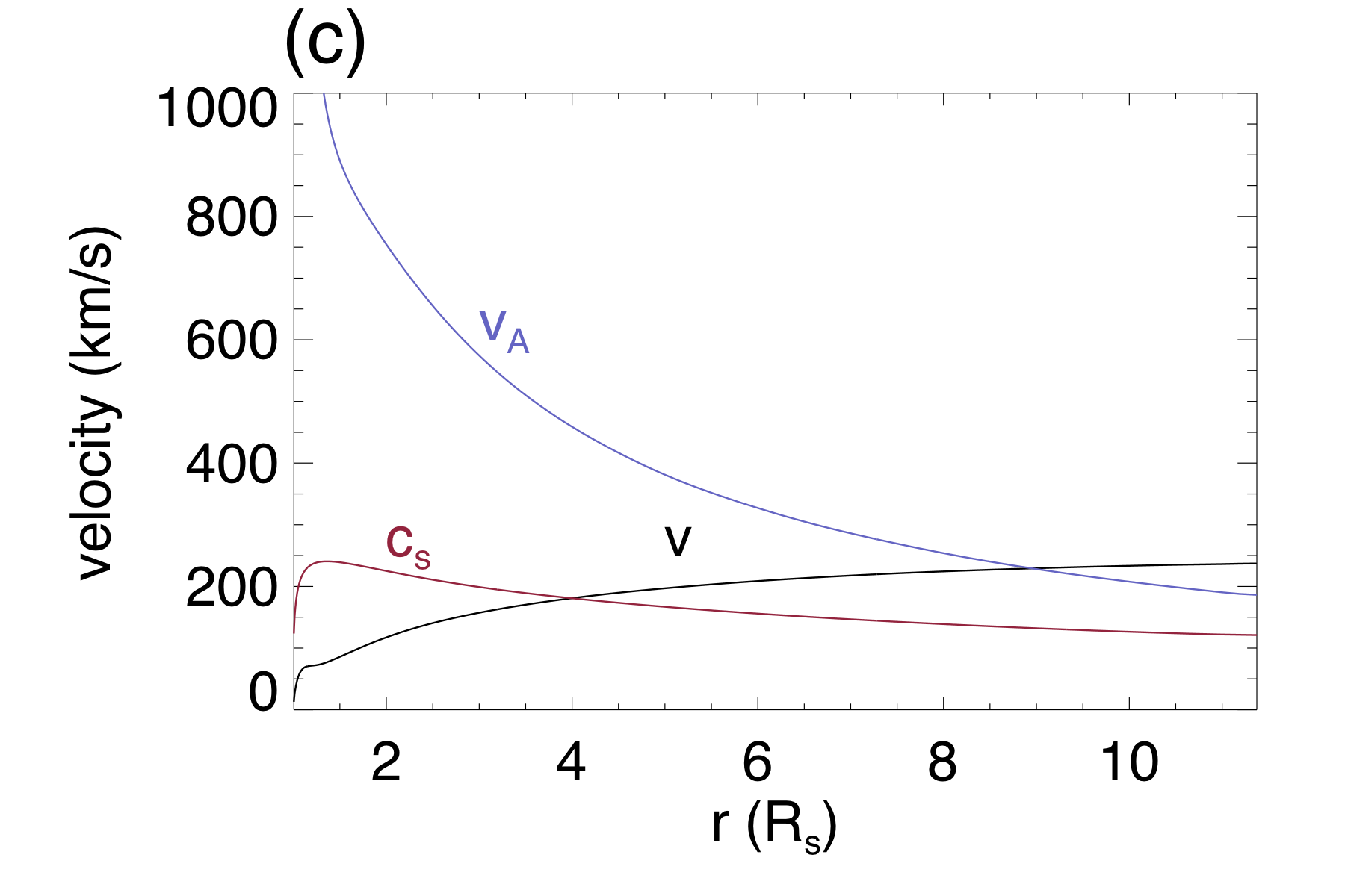
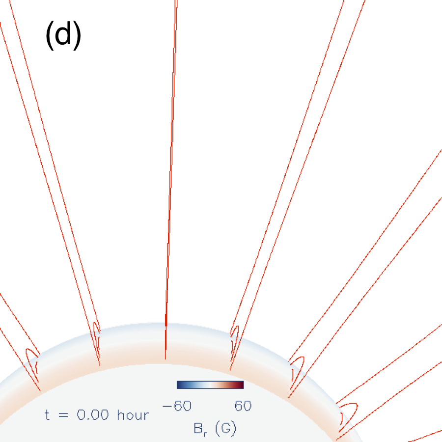
Although here we have used a different constant value (1.5 times the value used in F17) for setting the lower boundary pressure in equation (18) in F17, the resulting initial streamer solution remains very close to the initial WS streamer solution shown in Figure 3 of F17. As can be seen in Figure 2(a)(b), the initial state is a helmet streamer with a denser dome of closed magnetic field in approximate static equilibrium, surrounded by an ambient lower density open field region with an outflow. The outflow speed, the Alfvén speed, and the sound speed along an open field line (the green field line in Figures 2(a)(b)) as shown in Figure 2(c) are all very close to those of the WS solution in F17. Although the increased value tends to drive a higher coronal base pressure, the more mass flowing into the corona enhances cooling and in turn reduces downward heat conduction, thus as a net outcome the base pressure increase for the initial helmet steamer solution is small (%) and the overall initial state remains very close to the WS initial state in F17.
Into the initial helmet dome, we drive the emergence of a magnetic torus at the lower boundary in the same way as in the WS-L simulation described in section 3.1 of F17. The resulting evolution produced by the PROM simulation is shown in Figure 3 and the associated movie in the on-line version.

The top panels ((a)-(f)) show a sequence of snapshots of the 3D magnetic field lines. The field lines are colored as follows (same way as was done for Figure 5 of F17). A set of field lines traced from a fixed set of footpoints in the initial bipolar bands outside of the emerging flux region are colored red. For tracing the field lines from the emerging flux region, we track the footpoints on the lower boundary that connect to a fixed set of field lines of the subsurface emerging torus and color the field lines (green and blue field lines, and the black axial field line) based on the flux surfaces of the subsurface torus the field lines are on. The lower panels ((g)-(l)) of Figure 3 show synthetic SDO/AIA 304 Å channel emission images corresponding to each of the 3D field snapshots in the upper panels. The synthetic SDO/AIA 304 Å channel emission images are computed by integration along the line-of-sight (with the same viewing angle as that for the upper field line snapshots) through the simulation domain using equation (23) in F17. It can be seen from the AIA 304 Å emission (which has a peak temperature response at about K), cool prominence plasma condensations of elongated morphology develop in the emerged flux rope in the corona. As described in F17, the formation of the prominence is due to the onset of radiative instability or runaway radiative cooling of the plasma in the dips of the emerged flux rope field lines. We find the formation of a more extended and massive prominence in the PROM simulation compared to the WS-L case in F17, as can be seen by comparing the AIA 304 Å emission images in Figure 3 with those in Figure 10 of F17. Figure 4 shows the temporal evolution of the total magnetic energy and total kinetic energy (panel (a)), and the rise velocity tracked at the apex of the axial field line of the flux rope (panel (b)), from the PROM simulation (solid curves).

The “axial field line” refers to the field line that is traced from the footpoints on the lower boundary that connect to the axis of the driving emerging torus. The in Figure 4(b) is evaluated at the apex position of this axial field line. The axial field line reconnects during the onset of eruption, after which we continue to track the Lagrangian evolution of the the apex plasma element based on its velocity. Similar to the WS-L simulation in F17, we see in Figure 4(a) that the total magnetic energy increases from to hour as a coronal flux rope is built up (Figure 3(a)) due to the driving flux emergence at the lower boundary. The emergence is stopped at hour, when the total field line twist about the axis of the emerged flux rope reaches 1.83 winds, which is above the critical twist (1.25 winds) for the development of the kink instability derived for a line-tied, uniformly twisted cylindrical force-free flux tube (Hood & Priest, 1981). After the emergence is stopped, the coronal flux rope is found to undergo a long quasi-static phase (from to about hours), during which the rope remains confined under the streamer with close to zero rise velocity and with the total magnetic energy slowly declining for most of this quasi-static phase (see Figures 3(a)(b)(c) and solid curves in Figure 4). Towards the later part of the quasi-static phase (after about hour), we begin to see draining of the prominence mass in multiple branches (see Figures 3(i)(j)(k) and the online movie), and the flux rope starts a slow rise as it becomes significantly kinked (see Figures 3(c)(d)(e)). Eventually the central protrusion rises to a height where it can no longer be confined and develops a hernia-like ejective eruption (see Figures 3(e)(f)) at about hours, when shows a sudden decrease, shows a sudden increase, and the rise speed shows a significant acceleration (see solid curves in Figure 4). As can be seen from Figures 3(k)(l) and the movie, the prominence is lifted up into an erupting loop, with substantial draining along the legs of the erupting loop, and the draining prominence exhibits helical features as are often observed. The quasi-static phase after the emergence is stopped and the eventual hernia like eruption of the flux rope are qualitatively similar to the evolution in the WS-L case in F17. However in the present PROM simulation the quasi-static phase lasts about 3 times longer, about 27 hours, which is about 200 times the Alfvén transit time hours of the flux rope axis, and the development of the kink motion of the flux rope is significantly delayed. The long time scale compared to indicates the flux rope remains close to equilibrium during the quasi-static phase. The present flux rope is kept in equilibrium much longer because of the more massive and extended prominence condensations that form in the PROM simulation.
To study the effect of the prominence mass, we have also carried out the non-PROM simulation which suppresses the development of the cool prominence condensations (by modifying the radiative cooling and thermal conduction as described in section 2). The resulting evolution from the non-PROM simulation is shown in Figure 4 (dash-dotted curves) and Figure 5 (with an associated movie in the on-line version).

As is in the case of the PROM simulation, the flux emergence is stopped at hours when a significantly twisted coronal flux rope has been built up (see Figure 5(a)) with the total field line twist reaching 1.83 winds about the anchored axial field line. However, no significant cool prominence condensation forms in this case throughout the evolution as can be seen from the AIA images in Figures 5(d)(e)(f) and the movie. As a result, the development of the kink instability sets in much sooner as can be seen in Figure 5(b), where the flux rope has become significantly kinked and its central portion protruding to a significantly higher height compared to the prominence carrying flux rope shown in Figure 3(b) at an even later instant in time (about 2 hours later), for which there is still little development of the kink motion. The flux rope in the non-PROM case develops a hernia like eruption at about hours as can be seen in Figures 5(b)(c) and also in Figure 4 (dash-dotted lines), where undergoes a significant decrease, a significant increase, and the rise velocity a significant acceleration at about hours, far sooner than the onset of eruption for the PROM case. It appears that the formation of the massive prominence condensation has delayed the growth of the kink instability and the onset of eruption for a substantial time period, about 20 hours or , compared to the case without the prominence formation (compare the two curves in Figure 4(b)).
It has been shown for the WS-L case in F17 that the prominence carrying magnetic field is significantly non-force-free. This is further shown here for the prominence carrying flux rope in the PROM simulation. The top panel of Figure 6 shows several radial forces along the central vertical line through the middle of the flux rope shown in Figure 3(b) at time hours, during the quasi-equilibrium phase.

The forces shown are the magnetic tension force (black curve), the total pressure gradient force (blue curve), for which the total pressure is predominantly composed of the magnetic pressure because of the low plasma- as shown in the bottom panel, the sum (green curve), which is approximately the net Lorentz force, and the gravity force of the plasma (red curve). From the density profile in the middle panel, we can see that the height range of the prominence (with density exceeding about ) extends from the base to about , which covers a broader range of heights when compared to the WS-L case shown in Figure 19 of F17. The top panel of Figure 6 shows that for the height range containing the prominence, there is a significant net upward Lorentz force (green curve) that balances the downward gravity force (red curve) of the prominence. Thus the prominence carrying magnetic field is significantly non-force-free (despite being low plasma-), with the downward prominence gravity and the downward magnetic pressure gradient (blue curve) balancing the upward magnetic tension. The prominence gravity accounts for a major portion of the magnetic tension force. In the rest of the flux rope height range (from about to about ), the net Lorentz force (green curve) is nearly zero, i.e. nearly force-free, with the magnetic tension (black curve) nearly balancing the magnetic pressure gradient (blue curve). The significant gravity of the cool prominence mass on the magnetic field can suppress the kink instability of the otherwise force-free flux rope.
We find that the later onset of the kink motion of the flux rope takes place when the prominence begins to show draining and reduction of the prominence mass. Figure 7(a) shows the time variation of the total cool prominence mass in the corona evaluated as the total mass with temperature below K. Figure 7(b) is the same rise velocity of the flux rope as that shown in Figure 4(b) but shows a more zoomed-in view of the evolution during the quasi-static phase.

The cool prominence mass shows mostly continuous increase in the earlier part of the quasi-static phase. Later in the quasi-static phase we see episodes of prominence mass draining, marked in time by the two vertical dotted lines, corresponding to the time instances shown in Figures 3(i) and (j), where we see branches of prominence draining developing (see also the online movie). The latter monotonic decrease of the prominence mass (following the time marked by the second dotted line) corresponds with the final sustained acceleration and the dynamic eruption of the flux rope. Thus it appears that the initial growth of the prominence mass and its weight is able to suppress the development of the kink instability over a long period of time, from the time the emergence is stopped at hour to at least about hour, for a period of about , during which the rise speed remains close to zero with no significant acceleration (see Figure 7(b)). Some slow growth of the rise velocity and kink motion begin after about hour (see Figure 7(b) and Figures 3(c)(d)(e)), when episodes of prominence draining develop that lighten the prominence weight (Figures 3(i)(j)(k) and Figure 7(a)). The kink motion in turn promotes the draining of the prominence mass because of upward arching of the flux rope. Eventually the rise and kink motion brings the central protrusion of the flux rope to a height where it can no longer be confined and the flux rope undergoes an ejective eruption as shown in Figure 3 and the on-line movie.
3.2 Formation of the prominence-cavity system
Similar to the WS-L case shown in F17, we found in the PROM simulation that prominence condensations form in the dips of the flux rope field lines due to the in-situ development of the radiative (thermal) instability (e.g. Priest, 2014; Xia et al., 2011) of the plasma in the dips after their emergence into the corona. Figures 8, 9, and 10 show snapshots of a tracked field line that contains a dip, colored with temperature (Figure 8), pressure (Figure 9), and parallel velocity along the field line (Figure 10), for both the PROM case (upper row in the figures) and the non-PROM case (bottom row in the figures).


Figure 11 shows the temporal evolution of the temperature (top panel), density (middle panel), and pressure (bottom panel) at the center of the dip for the PROM case (black solid curve) and the non-PROM case (red dashed curve).

Just after the emergence of the dip (see the left snapshots in Figures 8 9 and 10 at hours, and also Figure 11), the emerged dip in both the PROM and non-PROM case has a similar initial (coronal) temperature (about K) and density (about ), with the dip in the PROM case being slightly denser and cooler (Figure 11). Also initially the parallel velocity shows an outflow from the dip in both the PROM and non-PROM cases (left panels in Figure 10). Both the PROM dip and the non-PROM dip undergo an initial cooling and decrease in pressure (see Figure 11), because they are not initially in thermal equilibrium, until about hours, when the non-PROM dip stabilizes to a relatively steady temperature (still coronal), density, and pressure, but in contrast the PROM dip undergoes a further, more rapid cooling, increase in density, and drop in pressure. This divergence in behavior is mainly due to the different radiative cooling functions used for the two cases, where the PROM case undergoes a run-away cooling because of the development of the radiative instability at the dip, cooling all the way to the low temperature end (at about K) of the cooling function, forming a prominence condensation (see the top row of Figure 8, and the top panel in Figure 11). With the significantly larger decrease of pressure in the dip of the PROM case due to prominence formation (see top panels of Figure 9 and the solid curve in bottom panel of Figure 11) compared to the non-PROM case (see the lower panels of Figure 9 and the red dashed curve in bottom panel of Figure 11), we find that the parallel velocity along the field line reverses direction to a converging flow towards the dip in the PROM case (see top panels of Figure 10) while in contrast the parallel velocity remains diverging away from the dip in the non-PROM case (see bottom panels of Figure 10). Thus the prominence formation is driven at the dip due to in-situ development of the radiative instability, similar to the case in F17, and the resulting lowered pressure at the dip continues to draw inflow of mass towards the dip from the footpoints (see the hours and hours panels in the top row of Figure 10). We find a continued inflow of mass towards the dip until about the time the dip disappears. With the use of a higher value of in equation (18) of F17 in the current PROM simulation, which increases the coronal base pressure given the same downward heat conduction flux, we find the formation of a more massive and extended prominence with more dips forming prominence condensations during the quasi-static phase compared to the WS-L case in F17. This is because with a higher base pressure (and density), the density in the emerged dips is higher, and thus more of the dips undergo the radiative instability to form prominence condensations. In Figure 7(a) we see two distinct stages of the prominence mass growth with different rates. One stage is from about hours to about hours with a sharper growth, and switches to a second stage of less steep growth from about hours to hours. The initial faster growth stage is when the newly emerged dips are undergoing radiative instability and forming new prominence condensations. The second stage is after the emergence has stopped, and no new prominence dips are forming, but the prominence mass is still growing due to the continuing converging flows into the dips that draw mass from the footpoints, as illustrated in the example shown in the top right panel of Figure 10.
With the formation of a more extended prominence in the PROM simulation, we also find the formation of a cavity surrounding the prominence in the flux rope, manifested in the synthetic AIA images shown in Figures 12 and 13 as viewed from two line-of-sights (LOS) that are nearly aligned with the length of the flux rope, at time hours.

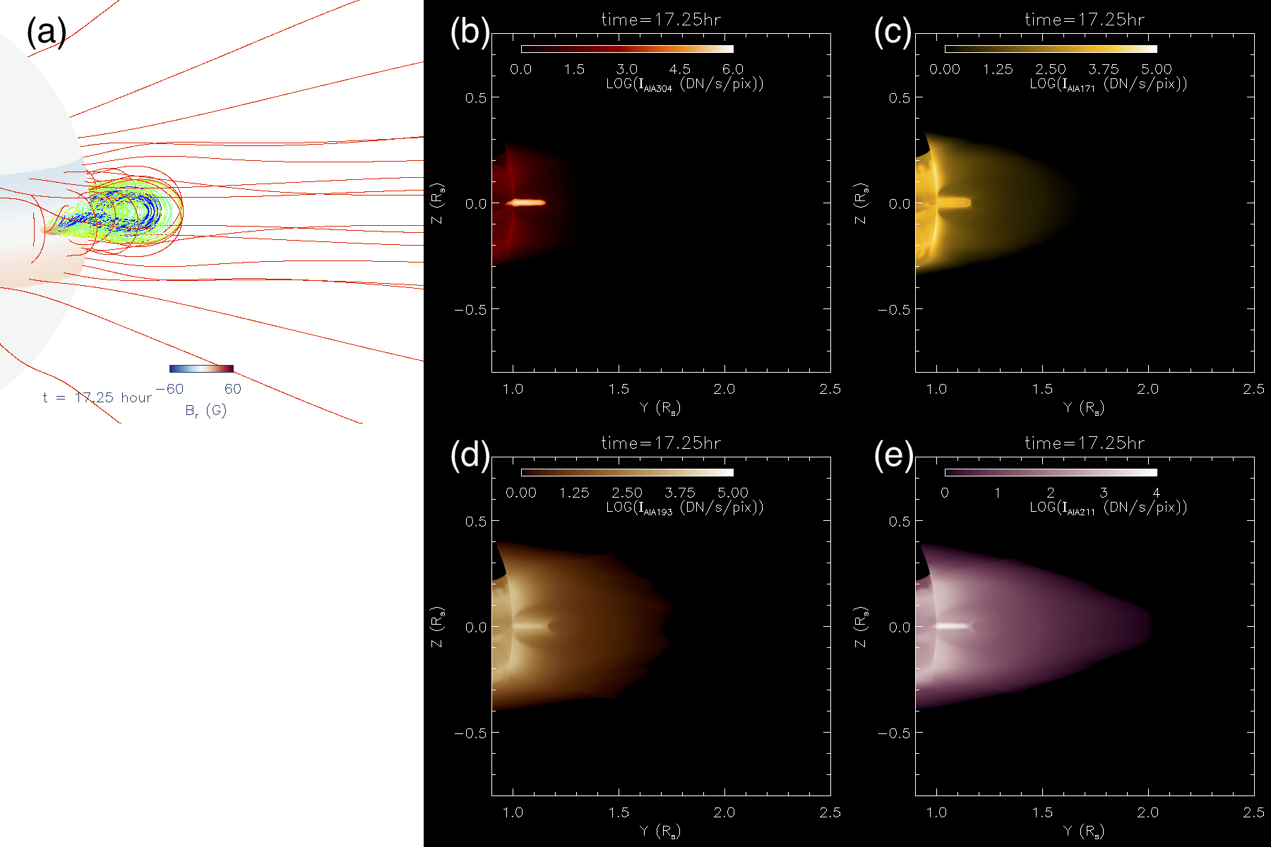
In the AIA 304 Å images (Figures 12(b) and 13(b)), we mainly see a narrow prominence extending from the solar surface up to a height of about above the limb. In the other hotter AIA channel images, we see that the bright narrow prominence is surrounded by a relatively darker cavity region enclosed in the brighter helmet dome, a configuration often seen in the observed coronal prominence-cavity system (e.g. Régnier et al., 2011; Gibson, 2015). The relatively darker cavity surrounding the prominence in the hotter AIA channel images (excluding the inner dark core seen on top of the prominence outlined by bright “horn”-like structures, to be discuss later) is produce by the LOS integration along a lower density and higher temperature tunnel that forms around the prominence. Figure 14 shows a horizontal cross-section of density (left panel) and temperature (right panel) through the flux rope at the constant height of , at the same time as that shown in Figures 12 and 13 at hours.
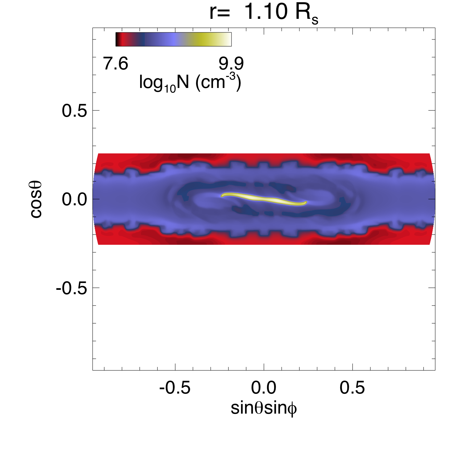
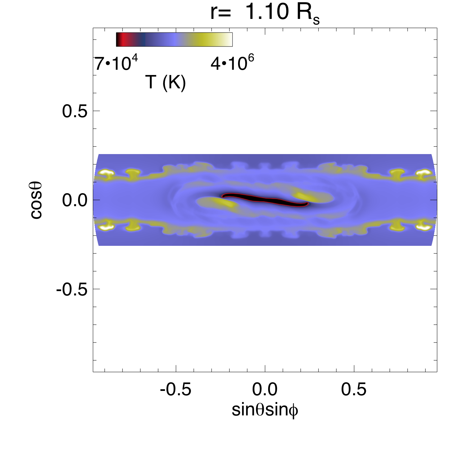
We see a central elongated filament condensation (of high density and low temperature) with an inverse-S shape surrounded by regions of relative low density and high temperature on both sides of the filament. Note that the rippling seen along the boundaries of the helmet fields is due to the instability and reconnection intermittently taking place higher up in different parts of the azimuthally extended current sheet above the helmet streamer. Figure 15 shows the profile of density (top panel) and temperature (bottom panel) along the slice through the center at of the horizontal cross-section shown in Figure 14.
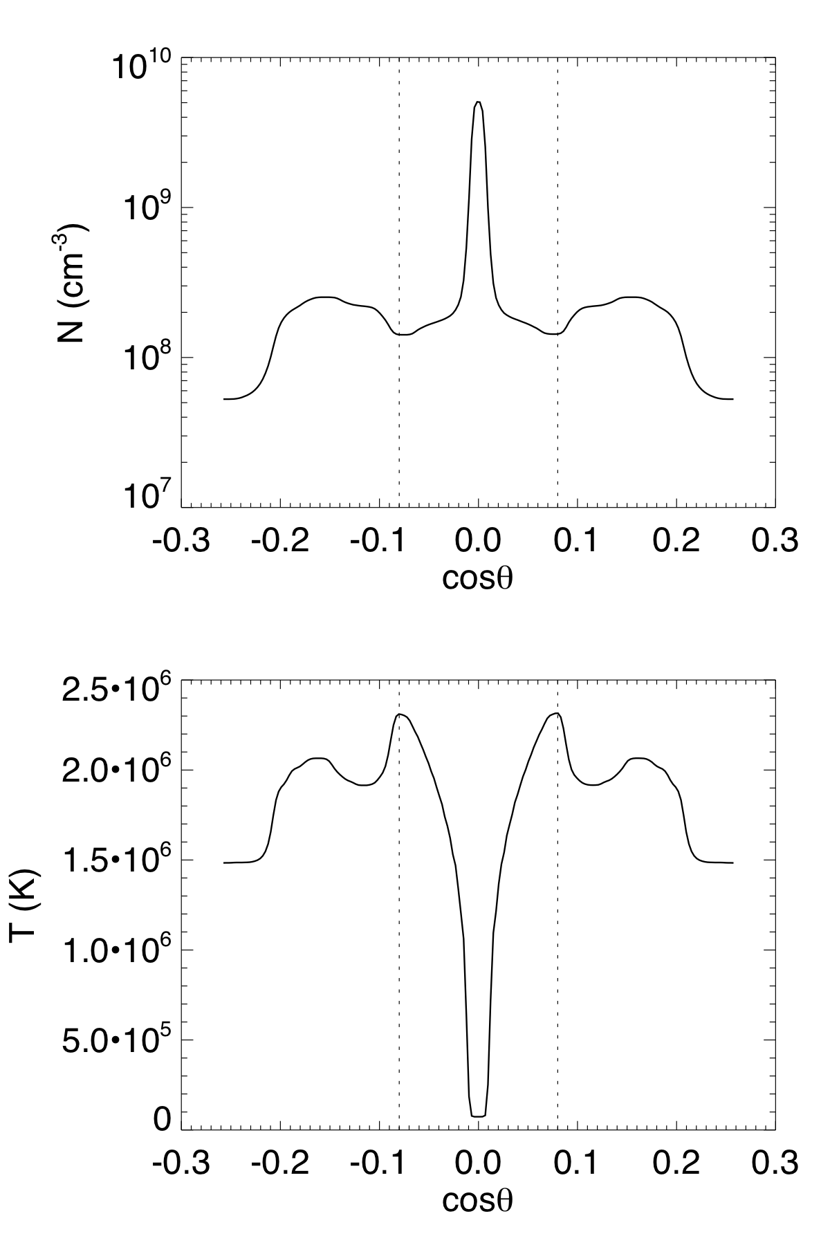
It can be seen that the cavity regions (at the locations marked by the dotted lines) on two sides of the central filament condensation have a lower density compared to the outer helmet rims and a relatively hot temperature of about 2.3 MK.
To understand what types of the magnetic field make up the prominence and the cavity, we show in Figure 16 a set of representative field lines colored according to density (left panels) and temperature (right panels), viewed from two different perspectives (upper and lower rows).
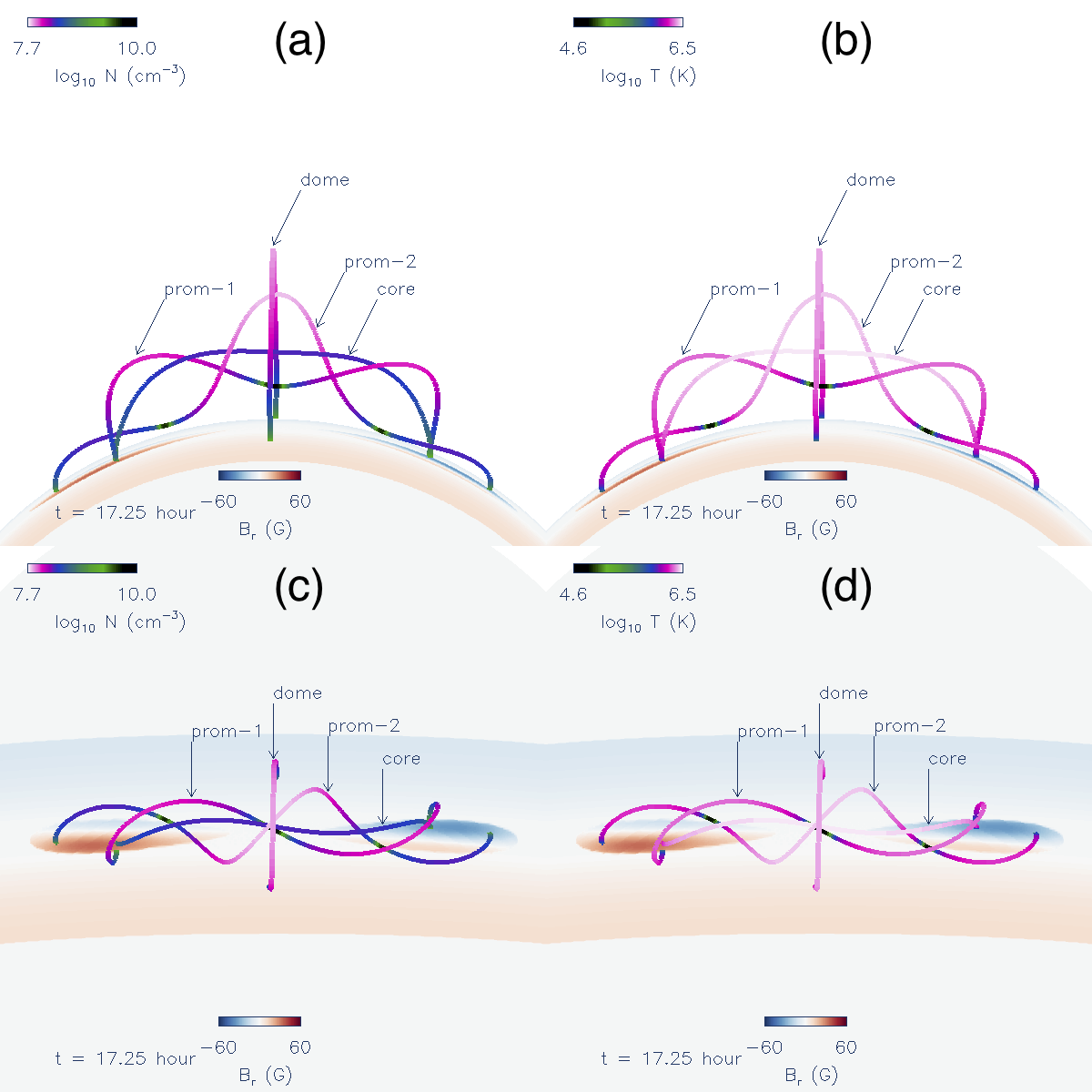
Two of the field lines (labeled “prom-1” and “prom-2”) are prominence carrying field lines with dips that contain prominence condensations (see the high density and low temperature dips in Figure 16). One of them (“prom-2”) has two prominence dips and the other (“prom-1”) contains one prominence dip. The field line labeled “dome” is a simple arcade field line in the helmet dome. The field line labeled “core” will be discussed later. It can be seen that for the prominence carrying field lines (“prom-1” and “prom-2”), the portions extending up from the prominence dips have lower density than the dome field line when compared at the same height (see Figure 16(a)). This is most clearly seen by comparing the color of the upper middle portion of the prom-2 field line with that of the dome field line at the same height. It can also be seen that the upper middle portion of the prom-2 field line extending up from the dips shows higher temperature than the dome field line when compared at the same height (see the field line color in Figure 16(b)). In Figure 17 we plot the profiles of pressure (top), density (middle), and temperature (bottom) as a function of height along the dome field line (black curves), the dip-to-top portions of the prom-1 (blue curves) and prom-2 (red curves) field lines, and the core field line (green curves) shown in Figure 16.
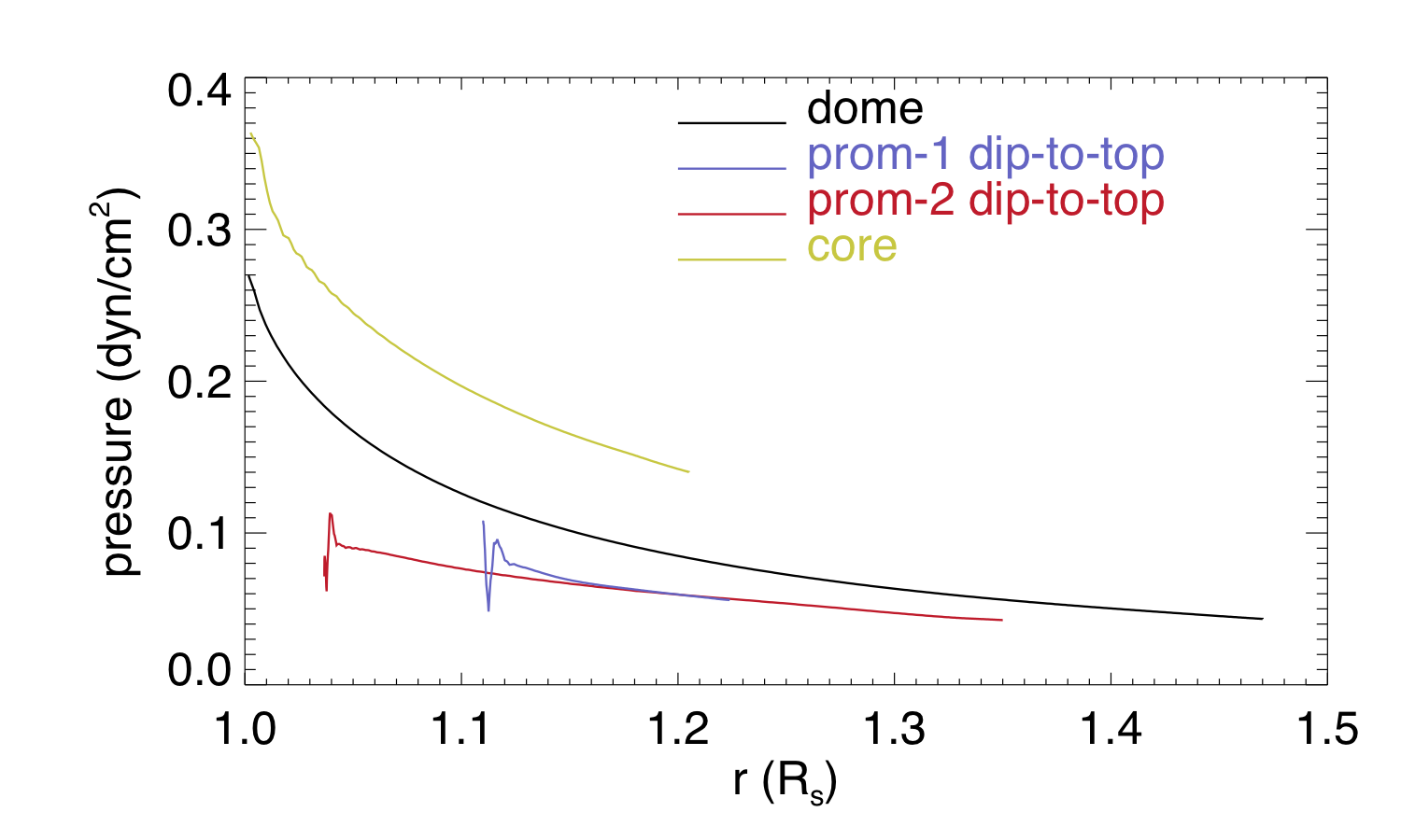
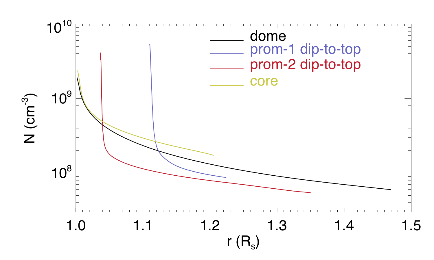
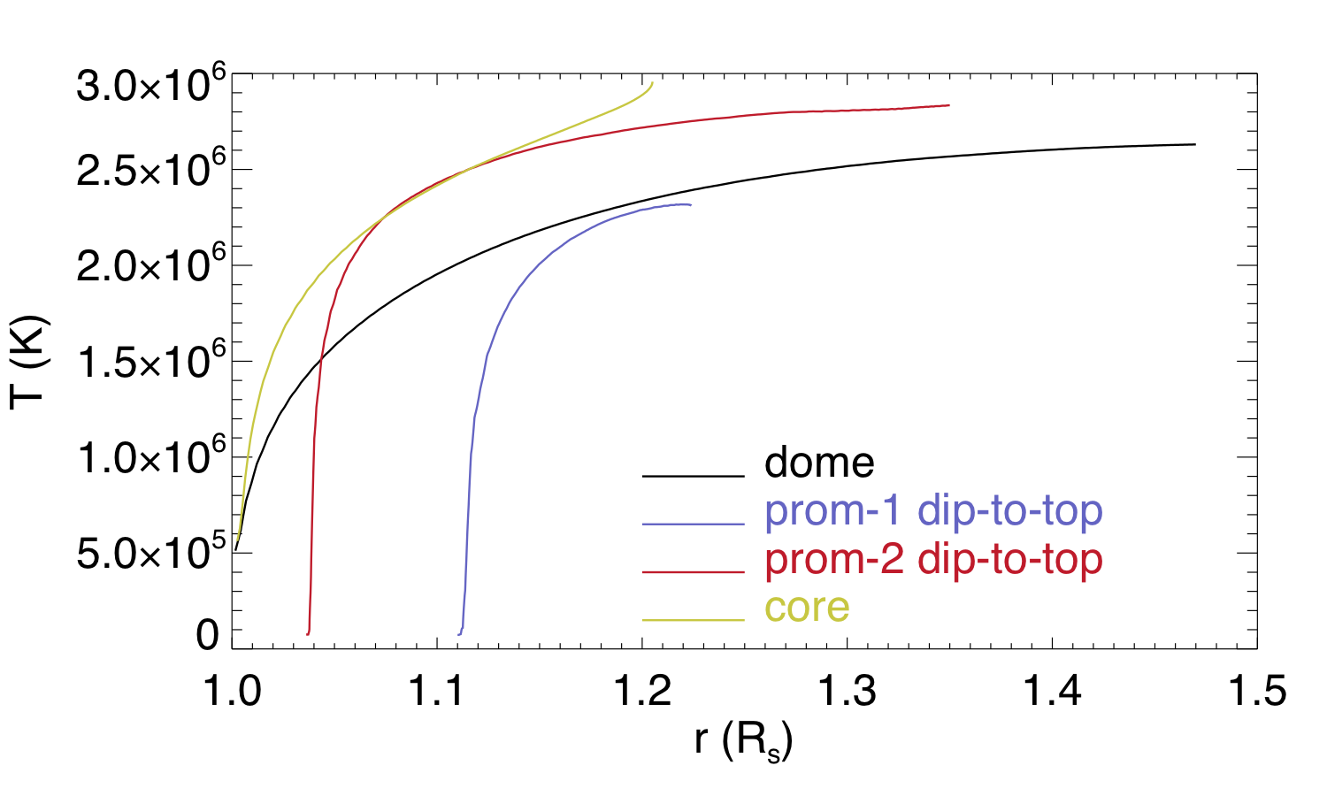
The blue curves in Figure 17 show the profiles along the portion of the prom-1 field line in Figure 16 from the bottom of the central dip to the right apex, and the red curves in Figure 17 show the profiles along the portion of the prom-2 field line in Figure 16 from the bottom of the left dip to the central apex. We find that the prominence carrying field lines develop a lower pressure compared to the arcade dome field line at all heights (see Figure 17 top panel), as a result of the formation of prominence condensations at the dips due to the run-away radiative cooling. Note that although the mean pressure is lower at the dips, large pressure fluctuations are seen at the bottom dips of the prom-1 and prom-2 field lines along the nearly horizontal dipped segments. The cooling time scale near the dip can be as short as the sound crossing time across the dip (F17) such that the hydrostatic balance is not well maintained and there are large pressure fluctuations along the dipped portion. The reduced mean pressure at the dips due to prominence formation drains plasma to the dips and establishes a more rarefied atmosphere along the portions of the field lines extending above the dips, resulting in lower density in those portions of the prominence carrying field lines compared to the dome field line at the same height (see Figure 17 middle panel). In some cases (such as for the prom-2 field line) it also leads to higher temperature in the field line portions extending above the dips compared to the dome field line (see the bottom panel of Figure 17) because of the reduction of cooling by the reduction of density. The cavity is thus formed by the rarefied portions of the prominence carrying field lines extending above the prominence dips. We find in the PROM simulation that the presence of the type of field lines containing two dips with prominence condensations (e.g. the prom-2 field line) in addition to the type (e.g. the prom-1 field line) that has only one prominence dip, produces a more continuous and extended low density cavity region along the length of the flux rope compared to the WS-L case in F17, in which only the latter type of prominence carrying field lines are present. As a result in the PROM simulation we obtain a distinct cavity surrounding the prominence in the AIA synthetic images viewed nearly along the length of the flux rope (Figures 12 and 13).
However we note that within the cavity seen in the synthetic AIA 193 Å and 211 Å channel images, there is a smaller central dark core region on top of the prominence, outlined by bright “horn”-like structures. We found that this central dark core is of a different character compared to the rest of the surrounding dark cavity region that is formed by the LOS contribution from the density depleted portions of the prominence carrying field lines extending above the prominence dips as discussed above. We found that the central dark core is threaded through by twisted field lines that contain no dips, as represented by the labeled “core” field line in Figure 16, which is hotter, has similar or higher density, and has higher pressure compared to the dome field line at the same height (see also the green curves showing the hight profiles of the core field line in Figure 17). Thus the central dark core inside the cavity in the AIA 193 Å and 211 Å channel images is due to LOS contribution from highly heated, twisted field lines that contain no dips, and it appears dark not because of low density, but because its high temperature (exceeding 3 MK) has gone above the peak sensitivity temperatures of the AIA 193 Å and AIA 211 Å channels. This cause is quite different from that for the surrounding dark cavity region. We found that the bright “horn”-like structures extending from the prominence is due to LOS contribution from field lines (not shown here) that contain shallow dips that are about to disappear, and contain denser plasma at coronal temperatures of about 1 to 2 MK that the AIA 193 Å and AIA 211 Å channels are sensitive to. Internal features inside a prominence cavity with a central dark region outlined by bright U-shaped prominence “horns” on top of the prominence has been observed in AIA 171 Å, 193 Å, and 211 Å channel images of prominence cavities (e.g. Berger, 2012; Su et al., 2015). The prominence-cavity system with the above internal features has also been produced by previous simulations of prominence formation by Xia et al. (2014) and Xia & Keppens (2016), which include the chromosphere at the lower boundary. Their interpretation of the structures obtained from the simulation is different from the nature of the structures found in our simulation. They found that the central dark cavity enclosed by the horns is threaded by both prominence-free dipped field lines and arched twisted field lines with no dips, while the outer cavity is formed by arched twisted field lines with no dips (Xia et al., 2014). They found that during prominence-cavity formation, density depletion occurs not only on prominence-loaded field lines threading cavity and prominence where in situ condensation happens (as is the case in our simulation), but also on prominence-free field lines due to mass drainage into the chromosphere. Their model of prominence-cavity formation is likely more realistic because of the inclusion of the chromosphere, and it allows the formation of filament channels or coronal cavities in absence of filament or prominence condensations.
4 Conclusions
Using the same numerical model described in F17, we have carried out simulations of the evolution of a coronal flux rope emerging into a coronal streamer, studying the cases with and without the formation of prominence condensations in the dips of the twisted flux rope field lines. In the case with prominence formation (the PROM simulation), we obtained the formation of a more massive and extended prominence in the emerged flux rope compared to the similar simulation in F17 (the WS-L simulation in that paper) by changing the specification of the lower boundary coronal base pressure. We found prominence condensations forming in more dips of the twisted field lines by the development of the radiative instability, and a more continuous and extended low density cavity region surrounding the elongated prominence/filament in the flux rope. The elongated filament is found to display a sigmoid shape. Also similar to the observations of prominence-cavity systems, a distinct dark cavity can be seen around the central narrow prominence in the helmet dome in the synthetic AIA 171 Å, 193 Å, and 211 Å emission images with the flux rope above the limb viewed along LOSs nearly aligned with its length. It is found that the cavity region is formed by the portions of the prominence carrying field lines that extend upward from the prominence dips, forming a more rarefied atmosphere along these portions of the field lines (compared to the dome arcade field lines) due to the lowered pressure at the dips by the formation of prominence condensations. The cavity region is also found to develop hotter temperatures (2 - 3 MK ) compared to the rim of the helmet dome (see e.g. red curve in bottom panel of Figure 17). In addition, it is found that within the cavity seen in the synthetic AIA 193 Å and 211 Å channel images, there is an apparent inner dark “cavity” on top of the prominence, outlined by bright “horn”-like structures. In our PROM simulation, this inner dark “cavity” however is of a different nature compared to the rest of the surrounding dark cavity: it is produced by LOS contribution from highly heated, twisted field lines that contain no dips, and appears dark not because of low density, but because of the high temperature (exceeding 3 MK) that has gone significantly above the peak sensitivity temperatures of the AIA 193 Å and AIA 211 Å channels.
Similar to F17, we found that the magnetic field in the region of the prominence condensations is significantly non-force-free, despite being low plasma-. A significant non-zero net Lorentz force, corresponding to a major fraction of the upward magnetic tension force of the dipped field lines, balances the weight of the cool prominence mass. Thus the prominence mass is playing a significant role in the stability and confinement of the coronal flux rope. By comparing the simulations with and without the formation of prominence condensations, we found that the weight of the prominence mass can suppress or delay the onset of the kink instability of an otherwise nearly force-free flux rope. It allows the flux rope in the PROM simulation to be confined in equilibrium significantly longer compared to the non-PROM case. The kink motion and the eruption eventually develop for the prominence carrying flux rope with substantial draining of the prominence plasma, which lightens the weight on the magnetic field. Our simulations suggest that the prominence mass is dynamically important for the equilibrium buildup and eruptive properties of CMEs. During the onset of the eruption, the synthetic AIA 304 images show that the prominence is lifted up into an erupting loop with helical features along the loop and significant draining along the legs of the loop, as often seen in observations.
References
- Amari et al. (2014) Amari, T., Canou, A., & Aly, J.-J. 2014, Nature, 514, 465
- Athay (1986) Athay, R. G. 1986, ApJ, 308, 975
- Aulanier et al. (2010) Aulanier, G., Török, T., Démoulin, P., & DeLuca, E. E. 2010, ApJ, 708, 314
- Berger (2012) Berger, T. 2012, in Astronomical Society of the Pacific Conference Series, Vol. 463, Second ATST-EAST Meeting: Magnetic Fields from the Photosphere to the Corona., ed. T. R. Rimmele, A. Tritschler, F. Wöger, M. Collados Vera, H. Socas-Navarro, R. Schlichenmaier, M. Carlsson, T. Berger, A. Cadavid, P. R. Gilbert, P. R. Goode, & M. Knölker, 147
- Chatterjee & Fan (2013) Chatterjee, P., & Fan, Y. 2013, ApJ, 778, L8
- Downs et al. (2012) Downs, C., Roussev, I. I., van der Holst, B., Lugaz, N., & Sokolov, I. V. 2012, ApJ, 750, 134
- Fan (2010) Fan, Y. 2010, ApJ, 719, 728
- Fan (2012) —. 2012, ApJ, 758, 60
- Fan (2017) —. 2017, ApJ, 844, 26
- Fan & Gibson (2007) Fan, Y., & Gibson, S. E. 2007, ApJ, 668, 1232
- Gibson (2015) Gibson, S. 2015, in Astrophysics and Space Science Library, Vol. 415, Solar Prominences, ed. J.-C. Vial & O. Engvold, 323
- Hood & Priest (1981) Hood, A. W., & Priest, E. R. 1981, Geophysical and Astrophysical Fluid Dynamics, 17, 297
- Jenkins et al. (2018) Jenkins, J. M., Long, D. M., van Driel-Gesztelyi, L., & Carlyle, J. 2018, Sol. Phys., 293, 7
- Low (1996) Low, B. C. 1996, Sol. Phys., 167, 217
- Low (2001) —. 2001, J. Geophys. Res., 106, 25141
- Munro et al. (1979) Munro, R. H., Gosling, J. T., Hildner, E., et al. 1979, Sol. Phys., 61, 201
- Priest (2014) Priest, E. 2014, Magnetohydrodynamics of the Sun (Cambridge, UK: Cambridge University Press)
- Régnier et al. (2011) Régnier, S., Walsh, R. W., & Alexander, C. E. 2011, A&A, 533, L1
- Su et al. (2015) Su, Y., van Ballegooijen, A., McCauley, P., et al. 2015, ApJ, 807, 144
- Török & Kliem (2005) Török, T., & Kliem, B. 2005, ApJ, 630, L97
- Török & Kliem (2007) —. 2007, Astronomische Nachrichten, 328, 743
- Török et al. (2011) Török, T., Panasenco, O., Titov, V. S., et al. 2011, ApJ, 739, L63
- Török et al. (2018) Török, T., Downs, C., Linker, J. A., et al. 2018, ArXiv e-prints, arXiv:1801.05903
- Webb & Hundhausen (1987) Webb, D. F., & Hundhausen, A. J. 1987, Sol. Phys., 108, 383
- Xia et al. (2011) Xia, C., Chen, P. F., Keppens, R., & van Marle, A. J. 2011, ApJ, 737, 27
- Xia & Keppens (2016) Xia, C., & Keppens, R. 2016, ApJ, 823, 22
- Xia et al. (2014) Xia, C., Keppens, R., Antolin, P., & Porth, O. 2014, ApJ, 792, L38