On the atomistic energetics of carbon nanotube collapse from AIREBO potential
Abstract
Molecular dynamics simulations based on the adaptive intermolecular reactive empirical bond order (AIREBO) were performed to probe hydrostatic pressure induced collapse of single-walled and double-walled carbon nanotubes. It was unveiled that the torsion term, which is a specific potential component involved in the AIREBO scheme, plays a vital role in stabilizing fully collapsed cross-sections of the carbon nanotubes. Evolution of the cross-sectional deformation along the loading-unloading curve was also elucidated, showing strong dependence on the presence of a structural defect on the outer carbon wall.
1 Introduction
Radial buckling of carbon nanotubes is one of the most important deformation modes that give rise to dramatic changes in their physical properties [1]. It is mainly a consequence of the hollow cylindrical structure of carbon nanotubes; the radial stiffness of the monoatomic cylinder, made by rolling up a graphene sheet, is much less than its remarkably high axial stiffness. Such the anisotropy in the stiffness allows cross-sectional buckling of carbon nanotubes when they are subjected to external high pressure or suffered from mechanical instability [2].
A primary example of the radial buckling mode is the one observed in pressurized many-walled carbon nanotubes. This mode is characterized by wavy-shaped cross-sections [3, 4, 5], which result from mechanical instability of outer walls that are reinforced by inner walls. Another example of radial buckling mode occurs in single-walled carbon nanotubes (SWNTs) with large radius. In the latter systems, loss of reinforcing inner walls makes the circular cross-section be energetically unstable. Beyond a threshold radius, therefore, they undergo spontaneous collapse in the radial direction [6, 7, 8, 9, 10, 11, 12, 13, 14, 15, 16, 17, 18, 19, 20, 21, 22, 23, 24]. A fully collapsed cross-section is composed of two parallel line segments whose ends are capped by two highly strained circular edges. Similar collapsing behavior was found to occur in double-wall carbon nanotubes (DWNTs) [25, 26, 27, 28].
From the physics perspective, the significance of nanotube collapse lies in that it may cause semiconductor-metal transition [29, 30], optical response change [31], magnetic moment quenching [32], as well as interwall sp3 bonding between adjacent walls [33, 34, 35, 36, 37, 38]. Furthermore, nanotube collapse is expected to provide a way of synthesizing closed-edged bilayer graphene nanoribbons [39, 40], which hold promise as building blocks in high-performance nanoelectronics because of the fascinating mechanical [19, 41, 42] and electrical properties [43, 40]. Against the backdrop, deep insight into an atomistic-scale mechanism of nanotube collapse will provide important clues for the discovery of novel physical properties of carbon nanotubes and their potential advantages in the field of nanoengineering.
In the present work, we perform molecular dynamics (MD) simulations of collapsing SWNTs and DWNTs with and without structural defects. Our MD simulation code is based on a broadly used interatomic potential (called AIREBO potential [44]; see §2.2), which makes it possible to express gradual changes from covalent to non-covalent bonds and vice versa in accord with interatomic distance as well as local atomic configuration. The main purpose of this work is to clarify what parts of AIREBO potential components should be dominant for driving and finally stabilizing the collapsed cross-section of nanotubes under high hydrostatic pressure. We also establish the pathway of cross-sectional deformation along the loading-unloading curve, paying attention to the way how the presence of structural defects in the wall gives feasible changes in the deformation pathway.
2 Method
2.1 Atomistic model of CNTs
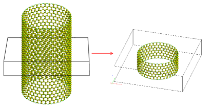
In this study we deal with zigzag SWNTs with the chiral index of (36,0) and DWNTs with (27,0)@(36,0). Figure 1 presents the simulation cell of a (36,0) SWNT. The unit cell is arranged such that the tube axis is parallel to the axis; the height of the simulation box depicted in Fig. 1 by solid lines equals three times the unit length of the (36,0) SWNT along the tube axis (12.78 Å), in which 432 carbon atoms are contained. The periodic boundary condition is imposed only in the direction.
We also deal with SWNTs and DWNTs endowed with a structural defect, called the Stone-Wales (SW) defect [45]. A SW defect is formed by a rotation of a C-C bond, which transforms four hexagonal carbon rings into two pentagons and two heptagons. This defect structure is a metastable state, in the sense that the system needs to overcome an activation barrier of several eV to realize it. It was suggested that the presence of SW defects gives an impact on the mechanical stability of collapsing carbon nanotubes [46]. In our actual simulations, one SW defect is imposed to each nanotube sample at the midpoint in the height of the unit cell.
2.2 Mechanical energy
Forces exerted on atoms are calculated by implementing the adaptive intermolecular reactive empirical bond order (AIREBO) interatomic potential [44]. The mechanical energy of a given nanotube is represented by
| (1) |
with and being atom numbering. The three terms involved in the parenthesis in Eq. (1) represent different energy components as explained below in turn.
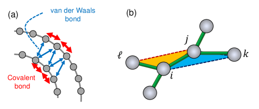
The first term, written by , is the second generation reactive empirical bond order (2g-REBO) potential [47]. It represents the potential energy of covalent bonds between nearest-neighbor carbon atoms, which are highlighted by thick arrows (colored in red) in Fig. 2(a). The value of depends not only on the interatomic distance between th and th atoms but also local atomic configuration around the two atoms. In general, the 2g-REBO potential makes it possible to evaluate with high accuracy the in-plane elasticity and bending rigidity of a graphene layer that consists of sp2 bonds.
The second term in the parenthesis, , accounts for the van der Waals (vdW) interaction between atoms that belong to different graphitic layers facing each other, as marked by thin arrows (colored in blue) in Fig. 2(a). The dependence of on the interatomic distance was set to be the same as that of the ordinary Lennard-Jones (LJ) 6-12 interatomic potential, as implied by the superscript; the well depth and equilibrium distance of the LJ potential were set to be 2.84 meV and 3.4 Å, respectively.
The third term, , the so-called “torsion term”, is derived from the energy required for torsional displacement of a carbon atom relative to its third nearest neighbor in the same graphitic layer. Figure 2(b) illustrates the way of evaluating the torsion term from local atomic configuration in a graphene layer. Note that a covalent bond that connects the atoms and is associated with four dihedral angles, one of which is the angle between the two triangular planes depicted in Fig. 2(b). Each of the four dihedral angles accounts for an interaction between one atom (e.g., labeled by ) and one of its third nearest neighbors (). A dihedral angle is either 0 or if all the four relevant atoms lie in a flat plane; specifically in the flat configuration, takes a maximum (or minimum) value at (or ) that corresponds to cis- (trans-)geometry of the C-C-C-C chain.
Among the three constituent terms in AIREBO, the working of the first two, and , on mechanical properties of collapsing carbon nanotubes has been intensively investigated. In particular, is known to play a crucial role in radial collapse of nanotubes, because the attraction and repulsion between opposing graphene walls are believed to stabilize collapsed cross-sections. The remaining one, , however, has not been paid sufficient attention thus far. This fact motivated the authors to examine the impact of torsional atomic interaction represented by this term on the nanotube collapse.
2.3 Torsion term in AIREBO
This subsection describes certain details in the mathematical expression of for later use. Suppose the local configuration of nearby six atoms, as depicted in Fig. 2(b), for which the relative position of the th atom locating at with respect to the th atom at can be represented by . Then is defined by the angle between the plane spanned by the two vectors and and the plane spanned by and , satisfying the relation:
| (2) |
Following Ref. [44], is expressed by
| (3) |
where
| (4) |
and
| (5) |
In Eq. (4), is a bond weight function that permits the identification of atom pairs as bonded (), nonbonded (), or partially dissociated (), depending on the interatomic distance [44]. In our MD simulations, the barrier height in Eq. (5) was set to be 0.3079 eV in accord with Ref. [44].
2.4 Hydrostatic pressure application
In principle, application of external hydrostatic pressure to a CNT implies that forces are exerted on all the constituent carbon atoms in the normal direction of the outmost wall. In practice, however, careful consideration is requisite for determining the normal direction of the wall at a given atom, since the wall is not a continuum layer but a discrete atomic network and thus there is no unique definition of the direction normal to the wall. In our simulations, the direction normal to wall is defined by the following procedure [5].
Since an atom in the honeycomb-shaped carbon network has three nearest neighbors, we find three isosceles triangles consisting of the atom and its two neighbors. We next define planes on which the three atoms lie and its normal vector. Then, a force vector parallel to the normal vector is applied to the three atoms that form the isosceles triangle. In this way, an atom receives three force vectors combined, each of which corresponds to the three planes on which the atom sits. The vector sum of the three force vectors determines the direction which we regard as the normal-to-wall direction at the given atom. For instance, when force vectors with a norm of 0.01 nN were assigned to the three atoms on the vertices of each isosceles triangle, they result in a load of 0.03 nN on an atom in the outmost graphene layer (note that each atom belongs to vertices of nine triangles).
2.5 Structural relaxation
The structural relaxation was performed in the following manner. First, structural perturbation was given to the initial configuration of concentric nanotube cylinders by MD calculation at a temperature () of 100 K for around 100 steps with the time step () of 2.0 fs. Then, the structure was relaxed employing the FIRE algorithm [48] until all forces exerted on atoms became less than 0.01 eV/Å. To rule out the possibility of the system falling into an unstable equilibrium, another MD run at K was performed for around 100 steps with fs and then the structure was relaxed again with the same tolerance for forces as above. The conditions for the initial perturbation were chosen so that the nanotube with cylindrical structure was slightly nudged to optimize its structure, because otherwise the structure would stay unchanged at the unstable equilibrium.
3 Deformation pathway
3.1 Radial deformation of SWNTs
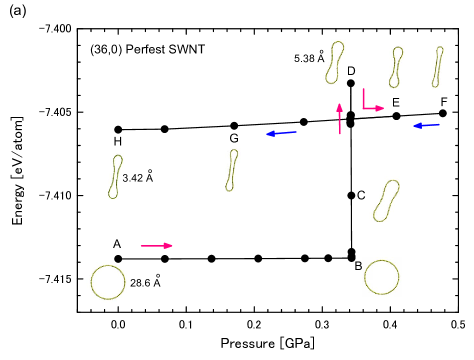
Figure 3 shows the pathway of radial deformation of (36,0) SWNTs under hydrostatic pressure. The vertical axis represents the mechanical energy of the system calculated by Eq. (1), and the horizontal axis indicates the pressure applied to the outer cylindrical wall. The panels of (a) and (b) correspond to a pristine SWNT without defect and a defective SWNT containing one SW defect, respectively. The line graph in the plot is a loading-unloading curve along which radial deformation proceeds in the alphabetic order; both the loading (indicated by arrows in magenta) and unloading (blue) is adiabatically imposed to the system. Sequential variation in the cross-section during the loading-unloading process is also illustrated in the plot. Numeric data in unit of Å, attached to a few cross-section views, show the interlayer distance, i.e., the distance of the two opposed walls at the closest point; for the circular cross-section, it merely means the diameter of the wall.
It follows from Fig. 3(a) that a pristine (36,0) SWNT with no defect shows an abrupt change in the energy at a critical state, i.e., at the state B in the plot. Across the state B, the system undergoes the transition from the initial circular cross-section to a radially deformed one, which causes a sudden increase in the energy while the applied pressure is kept to be constant. The energy keeps rising until the system arrives at another critical state, labeled by D in Fig. 3(a). Afterwards, the energy starts to decline suddenly, even though the magnitude of radial deformation continues to increase. Further loading results in a most-squeezed state F. At this extreme state, decompression starts and then the pressure is continued to be reduced adiabatically until the fully-unloaded state H. It should be noted that even after the load is completely released, the initial circular cross-section is not recovered. This implies that the nanotube collapse is stabilized due to a certain mechanism, as discussed later.
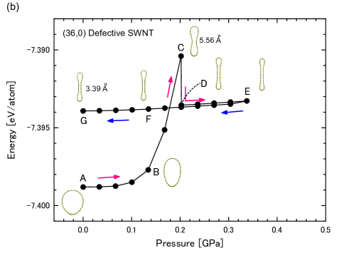
A similar deformation pathway was observed for the (36,0) defective SWNT with a SW defect, as shown in Fig. 3(b). The most important difference from the pristine-SWNT case is the absence of the first critical state at which the radial buckling occurs. Instead, the defective SWNT shows a gradual change in the cross-section from the initial state A to the highest energy state C. Beyond the state C, the system undergoes a similar deformation process to that in Fig. 3(a).
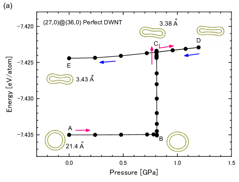
3.2 Radial deformation of DWNTs
Figure 4 shows the deformation pathway of (27,0)@(36,0) DWNTs; the panel (a) shows the result of a pristine DWNT, and the panel (b) shows the result of a defective DWNT in which one SW defect is embedded in the outer wall. As similar to the case of SWNTs, defect-induced vanishing of the radial buckling is observed in the defective DWNT. It is also found that the value of pressure requisite for collapsing is larger than that in the SWNT case. This is essentially because a DWNT can be viewed as a SWNT filled by a thinner SWNT. As such, it is reasonable that the inner tube provides mechanical support against radial compression [28] and thus a DWNT should show higher mechanical stability than a SWNT.
A noticeable difference from the case of SWNTs is the suppression of the overshoot in the loading-unloading curve near the state C shown in Figs. 4(a) and 4(b). This suppression can be attributed to lowering of the height in an activation barrier that separates elastic and plastic deformation phases, as will be discussed later.
4 Energy variation during radial deformation
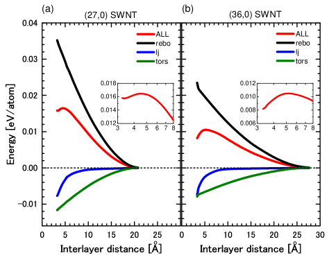
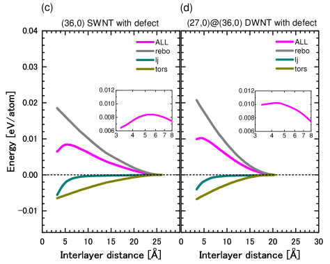
4.1 Contributions from different AIREBO components
Figure 5 shows the evolution in the mechanical energy of pressurized SWNTs and DWNTs with progress of reducing the interlayer distance. The horizontal axis shows the interlayer distance of the system that tends to decline as the radial compression proceeds. The vertical axis is the mechanical energy of the system calculated on the basis of the AIREBO potential scheme; contributions from three terms in Eq. (1) are each individually plotted as explained in the legend. A pristine (27,0) SWNT is also considered together with the nanotube systems discussed in Figs. 3 and 4, in order to investigate the effect of tube radius on the energy evolution.
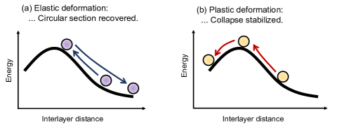
In all the plots in Fig. 5, it is commonly observed that the total energy starts to increase in a monotonic manner with decreasing interlayer distance, followed by a slight drop. In the vicinity of ca. 5 Å, the total energy curve shows a convex shape, as illustrated by the magnified view in the insets. This convex energy profile plays a role of the activation barrier beyond which the collapsed cross-section is stabilized; see Fig. 6 for schematic illustrations of energy evolution near the activation barrier. Given an insufficient radial deformation, the system can not reach a full collapse state but return to the initial circular cross-section after full unloading. In contrast, if the cross-section is significantly squeezed and the mechanical energy is raised enough to overcome the activation barrier, then the collapsed cross-section is stabilized even after full unloading
It is interesting to note that the interlayer distance which corresponds to the maximum position [e.g., 5.3 Å for pristine (36,0) SWNT ] is nearly equal to that realized in the second critical state in the deformation pathway [5.38 Å for pristine (36,0) SWNT as marked at the state D in Fig. 3(a)]. This implies that the overshoot height in the loading-unloading curve is determined by the activation barrier height estimated from the energy evolution curve in Fig. 5.
4.2 Mechanism of negative contribution from the torsion term
The most important observation in Fig. 5 is the monotonically decreasing trend in the energy curve derived from the torsion term. As followed from Fig. 5, the torsion term as well as the vdW term give negative contributions at all the interlayer distance, and their magnitudes are enhanced as the collapse advances. In contrast, the REBO term gives positive contribution at every interlayer distance. The sum of the positive and negative contributions results in the convex shape in the total energy curve.
We emphasize here that the absolute value of the torsion term contribution (negative) is always greater than that of the vdW term contribution (negative), as least in the range of interlayer distance we have considered. This fact indicates that the interatomic interaction described by the torsion term is fundamental for stabilizing the collapsed cross-section, together with the attractive interaction driven by the vdW forces between the two opposing walls. To the knowledge of the authors, the contribution from the torsion term to the radial deformation of carbon nanotubes has never been examined in detail thus far, compared with the intense studies on the counterparts regarding the REBO term and vdW term. In this sense, this is the first numerical evidence that the torsion term plays a significant role in the stabilization of collapsed cross-section of carbon nanotubes.

The reason why the torsion term decreases monotonically with approaching the interlayer distance is explained by considering the dependence of , defined by Eq. (5), on the dihedral angle . Figure 7 shows the profile of as a function of . We see from the figure that has a relatively sharp upward peak at , which corresponds to cis-type geometry of the --- carbon atomic chain that was depicted in Fig. 2(b). In addition, has a very broad minimum around , which corresponds to trans-type geometry of the --- chain.
An important feature of the profile is the significant asymmetry in the peak width between the upward peak at (sharp) and the plateau-like downward peak around (quite broad). The upward peak at indicates that cis-type geometry of a four-atom chain is energetically unstable and thus a feasible decline in the mechanical energy of chain will be observed if it is twisted (i.e., if deviates from 0). In contrast, the downward plateau around indicates that a trans-type chain will show only a slight change in energy even when it is twisted. Therefore, if both cis- and trans-type chains are twisted simultaneously with the same twist angle, then the energy decrease caused by cis deformation will overcome the energy increase by trans deformation, and thus the total energy of the two chains will be reduced.
The above argument regarding a pair of cis- and trans-type chains holds true for a monoatomic carbon cylinder (i.e., a SWNT), in which many cis- and trans-type chains are embedded. Under cross-sectional deformation of a SWNT, therefore, accumulation of local energy reduction derived from many twisted cis-chains will overcome a slight energy increase derived from many twisted trans-chains. As a result, of the system will decrease as the cross-sectional deformation proceeds.
Our finding provides a new insight into the atomistic-scale energetics of collapsing carbon nanotubes. It has been conventionally thought that the vdW force is a primary (and perhaps the only) driving force that stabilizes fully collapsed cross-sections, because the attractive nature of vdW interaction between to opposing carbon walls may result in high mechanical stability of the full collapse. But as clearly demonstrated in Fig. 5, the monotonic decline in the torsion-induced energy curve should be also indispensable for realizing the stabilization of the full collapse, taking a complementary role with the attractive vdW interaction. This is the main finding of this article.
4.3 Crossover between elastic and plastic deformation phases
We have seen that there is an activation barrier for stabilizing collapsed cross-sections. If the pressure-induced reduction in the interlayer distance at the closest point is not sufficiently small, then the system behaves elastically so that the initial circular cross-section will be recovered after complete unloading [see Fig. 6(a)]. In contrast, once the cross-section is squeezed sufficiently, then the system undergoes plastic deformation; in this case, the collapsed cross-section is stabilized even after complete unloading [see Fig. 6(b)]. In this context, it is interesting to probe the threshold interlayer distance that separates the elastic and plastic deformation phases.

Figure 8 presents a diagram of the threshold interlayer distance (ID) that separates elastic and plastic deformation phases. Each vertical segment indicates the marginal region of ID. If radial compression continues until ID is reduced below the bottom edge of the segment, then the system will fall into a full collapse even after complete unloading [see Fig. 6(a)]. If radial compression stops before ID goes below the upper edge of the segment, then the system will recover the initial circular cross-section after complete unloading [see Fig. 6(b)].
Figure 8(a) indicates that for SWNT, SW defect insertion leads to upward shifts both in the two threshold interlayer distances, i.e., the bottom limit of the elastic deformation phase and the upper limit of the plastic deformation phase. These upward shifts are intuitively understood as the defect insertion may cause reduced softening and thus the collapse becomes easy to occur even at a relatively large interlayer distance compared with the defect-free counterpart. But this softening effect is not significant for DWNTs as shown in Fig. 8(b). This is because in the defective DWNT, it is the outer wall that contains a defect; the inner wall is free from the defect and thus tends to push back the outer wall under radial compression.
5 Conclusion
We have conducted AIREBO-based MD simulations of collapsing SWNTs and DWNTs under hydrostatic pressure. The main finding is that the torsion term, one of the constituent potential terms in AIREBO, takes a vital role in stabilizing fully collapsed cross-section of carbon nanotubes. The novelty of this result stems from the fact that in established understandings, the vdW term is quite often considered as the only potential term that stabilizes collapsed cross-sections. Our simulation data clearly demonstrate that the sum of decreases both in the torsion term and the vdW term with progress of radial compression, not only the contribution from the vdW term, is the physical origin of carbon nanotube collapse. It was also found that the above conclusion holds true no matter whether the system contains a SW defect.
Acknowledgments
This work was supported by JSPS KAKENHI Grant Numbers JP 15H03888, 15H04207, and 15KK0220.
References
- [1] H. Shima, Buckling of carbon nanotubes: A state of the art review, Materials 5 (2012) 47–84.
- [2] H. Shima, M. Sato, Elastic and Plastic Deformation of Carbon Nanotubes, Pan Stanford Publishing, Singapore, 2012.
- [3] H. Shima, M. Sato, Multiple radial corrugations in multiwalled carbon nanotubes under pressure, Nanotechnology 19 (2008) 495705.
- [4] H. Shima, M. Sato, K. Iiboshi, S. Ghosh, M. Arroyo, Diverse corrugation pattern in radially shrinking carbon nanotubes, Phys. Rev. B 82 (2010) 085401.
- [5] Y. Umeno, I. Koike, A. Kusano, H. Shima, M. Sato, Atomistic origin of radial corrugation in a few-walled carbon nanotubes: A molecular dynamics study, Physica E 65 (2014) 135–140.
- [6] N. G. Chopra, L. X. Benedict, V. H. Crespi, M. L. Cohen, S. G. Louie, A. Zettle, Fully collapsed carbon nanotubes, Nature 1995 (377) 135–138.
- [7] L. X. Benedict, N. G. Chopra, M. L. Cohen, A. Zettl, S. G. Louie, V. H. Crespi, Microscopic determination of the interlayer binding energy in graphite, Chem. Phys. Lett. 286 (1998) 490–496.
- [8] G. H. Gao, T. Cagin, W. A. Goddard, Energetics, structure, mechanical and vibrational properties of single-wall carbon nanotubes, Nanotechnology 9 (1998) 184–191.
- [9] A. Pantano, D. M. Parks, M. C. Boyce, Mechanics of deformation of single- and multi-wall carbon nanotubes, J. Mech. Phys. Solids 52 (2004) 789–821.
- [10] J. A. Elliott, J. K. W. Sandler, A. H. Windle, R. J. Young, M. S. P. Shaffer, Collapse of single-wall carbon nanotubes is diameter dependent, Phys. Rev. Lett. 92 (2004) 095501.
- [11] H. J. Liu, K. Cho, A molecular dynamics study of round and flattened carbon nanotube structures, Appl. Phys. Lett. 85 (2004) 807–809.
- [12] B. Liu, M. F. Yu, Y. G. Huang, Role of lattice registry in the full collapse and twist formation of carbon nanotubes, Phys. Rev. B 70 (2004) 161402.
- [13] D. Y. Sun, D. J. Shu, M. Ji, F. Liu, M. Wang, X. G. Gong, Pressure-induced hard-to-soft transition of a single carbon nanotube, Phys. Rev. B 70 (2004) 165417.
- [14] X. H. Zhang, D. Y. Sun, Z. F. Liu, X. G. Gong, Structure and phase transitions of single-wall carbon nanotube bundles under hydrostatic pressure, Phys. Rev. B 70 (2004) 035422.
- [15] Z. W. Wang, Formation of a quenchable dense carbon form by compression of double-walled carbon nanotubes, J. Phys. Chem. B 108 (2004) 18192–18194.
- [16] T. Tang, A. Jagota, C. Y. Hui, N. J. Glassmaker, Collapse of single-walled carbon nanotubes, J. Appl. Phys. 97 (2005) 074310.
- [17] S. L. Zhang, R. Khare, T. Belytschko, K. J. Hsia, S. L. Mielke, G. C. Schatz, Transition states and minimum energy pathways for the collapse of carbon nanotubes, Phys. Rev. B 73 (2006) 075423.
- [18] J. Xiao, B. Liu, Y. Huang, J. Zuo, K. C. Hwang, M. F. Yu, Collapse and stability of single- and multi-wall carbon nanotubes, Nanotechnology 18 (2007) 395703.
- [19] M. Motta, A. Moisala, I. A. Kinloch, A. H. Windle, High performance fibres from ‘dog bone’ carbon nanotubes, Adv. Mater. 19 (2007) 3721– 3726.
- [20] T. Chang, Z. Guo, Temperature-induced reversible dominoes in carbon nanotubes, Nano Lett. 10 (2010) 3490–3493.
- [21] C. G. Zhang, K. Bets, S. S. Lee, Z. Z. Sun, F. Mirri, V. L. Colvin, B. I. Yakobson, J. M. Tour, R. H. Hauge, Closed-edged graphene nanoribbons from large-diameter collapsed nanotubes, ACS Nano 6 (2012) 6023–6032.
- [22] Y. Li, Edge-closed graphene nanoribbons fabricated by spontaneous collapse of few-walled carbon nanotubes, Phys. Chem. Chem. Phys. 16 (2014) 1921–1929.
- [23] M. He, J. Dong, K. Zhang, F. Ding, H. Jiang, A. Loiseau, J. Lehtonen, E. I. Kauppinen, Precise determination of the threshold diameter for a single-walled carbon nanotube to collapse, ACS Nano 8 (2014) 9657–9663.
- [24] T. F. T. Cerqueira, S. Botti, A. San-Miguel, M. A. Marques, Density-functional tight-binding study of the collapse of carbon nanotubes under hydrostatic pressure, Carbon 69 (2014) 355–360.
- [25] X. Yang, G. Wu, J. Dong, Structural transformations of double-walled carbon nanotube bundle under hydrostatic pressure, Appl. Phys. Lett. 89 (2006) 113101.
- [26] B. Anis, K. Haubner, F. Börrnert, L. Dunsch, M. H. Rümmeli, C. A. Kuntscher, Stabilization of carbon nanotubes by filling with inner tubes: An optical spectroscopy study on double-walled carbon nanotubes under hydrostatic pressure, Phys. Rev. B 86 (2012) 155454.
- [27] A. L. Aguiar, R. B. Capaz, A. G. Souza Filho, A. San-Miguel, Structural and phonon properties of bundled single- and double-wall carbon nanotubes under pressure, J. Phys. Chem. C 116 (2012) 22637.
- [28] R. S. Alencar, W. Cui, A. C. Torres-Dias, T. F. T. Cerqueira, S. Botti, M. A. L. Marques, O. P. Ferreira, C. Laurent, A. Weibel, D. Machon, D. J. Dunstan, A. G. S. Filho, A. San-Miguela, Pressure-induced radial collapse in few-wall carbon nanotubes: A combined theoretical and experimental study, Carbon 125 (2017) 429–436.
- [29] A. Barboza, A. Gomes, B. Archanjo, P. Araujo, A. Jorio, A. Ferlauto, M. Mazzoni, H. Chacham, B. R. A. Neves, Deformation induced semiconductor-metal transition in singlewall carbon nanotubes probed by electric force microscopy, Phys. Rev. Lett. 100 (2008) 256804.
- [30] C. Giusca, Y. Tison, S. Silva, Evidence for metal-semiconductor transitions in twisted and collapsed double-walled carbon nanotubes by scanning tunneling microscopy, Nano Lett. 8 (2008) 3350–3356.
- [31] K. Thirunavukkuarasu, F. Hennrich, K. Kamarás, C. Kuntscher, Infrared spectroscopic studies on unoriented single-walled carbon nanotube films under hydrostatic pressure, Phys. Rev. B 81 (2010) 045424.
- [32] E. Diniz, R. Nunes, H. Chacham, M. Mazzoni, Bistability, softening, and quenching of magnetic moments in Ni-filled carbon nanotubes, Phys. Rev. B 81 (2010) 153413.
- [33] A. Fonseca, T. Borders, R. Baughman, K. Cho, Load transfer between cross-linked walls of a carbon nanotube, Phys. Rev. B 81 (2010) 045429.
- [34] M. Sakurai, S. Saito, Pressure-induced structural phase transition of small-diameter carbon nanotubes, Physica E 43 (2011) 673–676.
- [35] Z. Xia, P. Guduru, W. Curtin, Enhancing mechanical properties of multiwall carbon nanotubes via interwall bridging, Phys. Rev. Lett. 98 (2007) 245501.
- [36] Z. Xia, P. Guduru, W. Curtin, Multiwall nanotubes can be stronger than singlewall nanotubes and implications for nanocomposite design, Phys. Rev. Lett. 103 (2009) 045502.
- [37] T. Filleter, R. Bernal, S. Li, H. Espinosa, Ultrahigh strength and stiffness in cross-linked hierarchical carbon nanotube bundles, Adv. Mater. 23 (2011) 2855–2860.
- [38] Y. Zhang, C. Wang, Y. Xiang, Bending behavior of double-walled carbon nanotubes with interwall bonds, J. Appl. Phys. 109 (2011) 083516.
- [39] C. Zhang, K. Bets, S. S. Lee, Z. Sun, F. Mirri, V. L. Colvin, B. I. Yakobson, J. M. Tour, R. H. Hauge, Closed-edged graphene nanoribbons from large-diameter collapsed nanotubes, ACS Nano 6 (2012) 6023–6032.
- [40] D. H. Choi, Q. Wang, Y. Azuma, Y. Majima, J. H. Warner, Y. Miyata, H. Shinohara, R. Kitaura, Fabrication and characterization of fully flattened carbon nanotubes: A new graphene nanoribbon analogue, Sci. Rep. 3 (2013) 1617.
- [41] X. H. Zhong, R. Wang, L. B. Liu, M. Kang, Y. Y. Wen, F. Hou, J. M. Feng, Y. L. Li, Structures and characterizations of bundles of collapsed double-walled carbon nanotubes, Nanotechnology 23 (2012) 505712.
- [42] J. J. Vilatela, L. Deng, I. A. Kinloch, R. J. Young, A. H. Windle, Structure of and stress transfer in fibres spun from carbon nanotubes produced by chemical vapour deposition, Carbon 49 (2011) 4149–4158.
- [43] R. Senga, K. Hirahara, Y. Nakayama, Nanotorsional actuator using transition between flattened and tubular states in carbon nanotubes, Appl. Phys. Lett. 100 (2012) 083110.
- [44] S. J. Stuart, A. B. Tutein, J. A. Harrison, A reactive potential for hydrocarbons with intermolecular interactions, J. Chem. Phys. 112 (2000) 6472.
- [45] A. J. Stone, D. J. Wales, Theoretical studies of icosahedral C60 and some related species, Chem. Phys. Lett. 128 (1986) 501–503.
- [46] C.-C. Ling, Q.-Z. Xue, L.-Y. Chu, N.-N. Jing, X.-Y. Zhou, Radial collapse of carbon nanotubes without and with Stone-Wales defects under hydrostatic pressure, RSC Advances 2 (2012) 12182–12189.
- [47] D. W. Brenner, O. A. Shenderova, J. A. Harrison, S. J. Stuart, B. Ni, S. B. Sinnott, A second-generation reactive empirical bond order (REBO) potential energy expression for hydrocarbons, J. Phys.: Condens. Matter 14 (2002) 783.
- [48] E. Bitzek, P. Koskinen, F. Gähler, M. Moseler, P. Gumbsch, A reactive potential for hydrocarbons with intermolecular interactions, Phys. Rev. Lett. 97 (2006) 170201.