Resonant spin wave excitation in magnetoplasmonic bilayers by short laser pulses
Abstract
In magnetically ordered solids a static magnetic field can be generated by virtue of the transverse magneto-optical Kerr effect (TMOKE). Moreover, the latter was shown to be dramatically enhanced due to the optical excitation of surface plasmons in nanostructures with relatively small optical losses. In this paper we suggest a new method of resonant optical excitations in a prototypical bilayer composed of noble metal (Au) with grating and a ferromagnet thin film of yttrium iron garnet (YIG) via frequency comb. Based on magnetization dynamics simulations we show that for the frequency comb with the parameters, chosen in resonant with spin-wave excitations of YIG, TMOKE is drastically enhanced, hinting towards possible technological applications in the optical control of spintronics systems.
I Introduction
Ideas and concepts developed in photonics have been recently applied in related fields, in particular in physics of collinear magnets. The rapidly advancing area of magnonics represents photonics with spin waves, or, collective propagating magnetization excitations in magnetic materials. Thanks to their unique linear and nonlinear properties Demokritov2012 ; Khitun2010 ; Haldar2017 ; Fischer2017 ; Tabuchi2015 spin waves can be successfully employed in next generation spintronics devices and quantum computing. In the meantime, further implication in technology requires excitation of spin waves at short length- and time-scales. This can be achieved by the optical excitation of magnetic system with femtosecond laser pulses VanKampen2002 ; kimel2005ultrafast ; Hansteen2006 ; Stanciu2007 ; Bigot2009 ; Satoh2012 ; Au2013a . Despite a variety of ways of optical generation of spin waves, the nonthermal magneto-optical processes such as inverse Faraday and inverse Kerr are of particular importance, since they are characterized by high time resolution and do not require heating of the sample. The essence of the effect is that the external optical electric field induces magnetic field via the nonlinear processes such as e.g. stimulated Raman scattering Popova2012 . Thus induced magnetic field drives spin waves in a magnetic structure. Recently, it was anticipated that in inhomogeneous media the expression may be non-zero even for the linearly polarized wave. In planar geometry, this effect takes place for TM polarization only, and the induced magnetic field is perpendicular to the plane of incidence, realizing thus the inverse transverse magneto-optical Kerr effect (TMOKE) PhysRevB.86.155133 . Among structures which allow inverse TMOKE are magnetoplasmonic systems Bossini2016 , since they facilitate electric field localization and an effective chirality of surface plasmon polariton can approach a unity.
It is clear that in continuous wave regime the induced magnetic field is time-independent, whereas under femtosecond laser pulses this field follows the intensity profile. Therefore, a much higher efficiency of spin wave generation can be achieved in the case of resonant excitation, when the intensity profile is periodic with a frequency close to that of ferromagnetic resonance, which is typically of the order of 1 GHz. Recently, it has been demonstrated experimentally Jaeckl2017 that using clocked laser excitation can substantially enhance the efficiency of the spin wave generation at the bottom of magnon band, followed by their diffusion. However, for the direct implication in data processing resonant excitation of spin waves with fixed both frequency and wavevector (and group velocity, as a result) is of vital importance.
In this paper we propose a combination of a magnetoplasmonic structure and clocked laser excitation for the resonant excitation of spin waves. We first design the structure and numerically model the distribution of electromagnetic field under the clocked laser excitation. Using the data we evaluate the induced magnetic field and study magnetization dynamics based on numerical solution of Landau-Lifshitz-Gilbert (LLG) equation stancil2009spin . We provide an estimate for a realistic structure, where a resonant excitation of spin waves can be achieved with efficiency enhancement of at least two orders of magnitude as compared to that in the free magnetic film under pulsed excitation.
II Model system
Among various magnetic materials of collinear ordering yttrium iron garnet (YIG) is characterized by the best magneto-elecctrical and magneto-optical properties, which stand out this material for microwave applications Musa2007 . YIG belongs to the class of magnetically ordered structures with cubic symmetry pirro2014spin ; collet2017spin and rather low loss Pardavi2000 , and is successfully used in a broad range of spintronics applications.
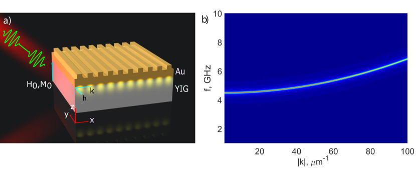
We therefore consider a hybrid nanostructure consisting of a thin film of YIG and Au discrete grating on the top (geometry of the system is schematically depicted in Fig. 1a under short laser pulses.
To study magnetization dynamics induced by laser pulses we are to numerically solve LLG equation
| (1) |
where is the gyromagnetic ratio of an electron ( GHz/T). In general LLG equation describes precession of the magnetization, , around the effective magnetic field, , created by electrons of a ferromagnet, whereas the relaxation rate to the direction of the field is associated with the Gilbert damping parameter, . We assume the thin layer of YIG is initially polarized along the axis , as shown in Fig. 1a, and is placed to the external field . Being irradiated with laser pulses results in the emergence of the magnetic field directed perpendicular to the plain of incidence via TMOKE mechanism. The latter gives rise for the magnetization direction to slightly deviate from collinear ordering, and thus to spin waves excitation. To get spin wave spectrum we linearize Eq. (1) with respect to in-plane components of the magnetization , i.e., we plug into (1) on condition that . We derive after straight forward algebra,
| (2) |
The properties of YIG can be well approximated using the microscopic Hamiltonian which includes Heisenberg exchange interaction, magnetocrystalline anisotropy, and Zeeman coupling. Thus, the effective field can be represented as follows:
| (3) |
where we assume the summation over repeated indexes; is the tensor of magnetocrystalline anisotropy, . In Eq. (3) the exchange tensor is reduced to a scalar owing to the cubic lattice symmetry of YIG with 3 10-16 m2, while corresponds to the effective anisotropy magnetic field stancil2009spin . Typically, the effective anisotropy field is material-specific and equals 4.6 kA/m for YIG. In the following, we assume and are parallel to (see Fig.1a), thus being normal to Au–YIG interface. We put T, and set to be equal to the saturation magnetization of YIG, i.e., kA/m. It is therefore clear that with no present in the system the vector product is zero, producing no magnetization precession.
III Results and discussion
We put the Gilbert damping parameter 3.2 10-4, although it can be decreased as shown in Ref. dubs2017sub . Fourier transforming the equation of motion (2) to makes it possible to evaluate the spin wave spectrum from . Thus obtained the magnon dispersion relation for the YIG thin film in the presence of is shown in Fig. 1b. One can clearly observe that magnons are positioned in 4-7 GHz range for -vector ranging between 1 and 100 ), and are characterized by a very narrow dispersion line (about 40 MHz) because of low Gilbert damping. Therefore, the direct optical excitation of magnons is hardly to be achieved.
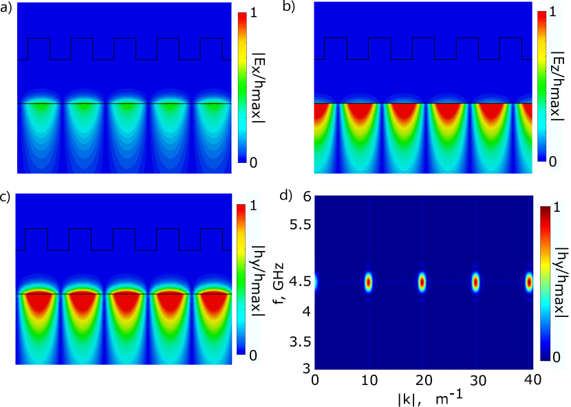
To bind optical waves (in the form of plasmons, for example) with spin waves we propose to use a gold grating that amplifies the electric field and are to determine the field distribution due to strong field localization via excitation of plasmonic resonances maier2007plasmonics ; giannini2011plasmonic . To be more specific, we suppose: the thickness of Au layer is 100 nm, periodicity is 100 nm, the width and the height of array’s element are 50 nm. The latter allows us to excite plasmons on the Au-YIG interface with the -vector to be m-1.To estimate the distribution of magnetic field inside the hybrid nanostructure we impose the periodic boundaries in and directions. We further proceed with eigenmode simulation in CST Microwave Studio: the electric field distribution clearly reveals that excited field of plasmons possesses two phase-shifted components of the electric field (see 2a-b) inside the YIG film. Thus, it induces time-independent magnetic polarization via the TMOKE mechanism PhysRevB.86.155133 .
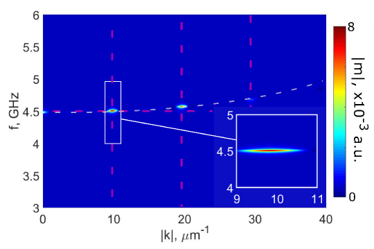
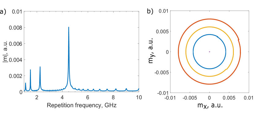
The time-independent magnetic field serves as a source of spin waves in accordance with Eq. (3). To introduce time-dependence we propose to excite plasmons in the nanostructure by a train of Gaussian pulses with the repetition rate chosen in resonance with the frequency of magnons in the YIG thin film. We assume the duration of each pulse is 40 ps that is shorter in comparison with the repetition rate. As we discussed earlier, the Au grating allows us to generate electromagnetic field with a fixed value of the wavevector m-1, thus, in full accordance with the magnon dispersion of YIG shown in Fig. 1a the resonance frequency of the spin waves in the magnetoplasmonic bilayer under consideration is 4.5 GHz. To be more realistic we put the finite size of hybrid nanostructure limited by 1 . Such a value of repetition rate is difficult to achieve using only common methods of Gaussian pulses train generation. Meanwhile, using a frequency comb technique facilitates overcoming this problem by generating the Gaussian pulses with high repetition rate up to THz range Wu:13 ; Kippenberg2011555 . The dispersion of induced magnetic field consists of a discrete set of spots as shown in Fig.2d, the latter happens due to the periodicity of the structure and an excitation properties of frequency combs. Therefore, by solving the equation of motion with thus obtained we can get the spin waves dispersion as well as to recover their time and space dependence by performing inverse discrete Fourier transformation. The resulting dispersion is depicted in Fig. 3. As it was expected there is only one spot on coincidence of dispersion diagrams of excitation magnetic field and spin waves in YIG (hot spots of magnetic field diagram are represented by crossing of straight dashed pink lines and dispersion line of magnons in YIG is represented by white dashed curve).
The dependence of kh/h_max
IV Conclusions
In the current studies we considered a typical magnetoplasmonic structure, that represents the bilayer of a thin film YIG covered by a layer of gold with grating and explicitly showed that TMOKE emerging in such a structure may be dramatically enhanced using frequency comb technique. In fact, for the repetition rate chosen to be in resonant with the ferromagnetic resonance of the magnetic layer the direct numerical solution to LLG equation reveals a desired behavior. We believe that our results will trigger experimental activity in rapidly advancing area of research right in the border between plasmonics and spintronics.
Acknowledgements
We acknowledge the support from the Russian Science Foundation under the Project No. 17-12-01359.
References
- (1) S. O. Demokritov and A. N. Slavin, Magnonics: From fundamentals to applications (Springer Science & Business Media, 2012).
- (2) A. Khitun, M. Bao, and K. L. Wang, Magnonic logic circuits, J. Phys. D: Appl. Phys. 43, 264005 (2010).
- (3) A. Haldar, C. Tian, and A. O. Adeyeye, Isotropic transmission of magnon spin information without a magnetic field, Sci. Adv. 3, 1700638 (2017).
- (4) T. Fischer, M. Kewenig, D. A. Bozhko, A. A. Serga, I. I. Syvorotka, F. Ciubotaru, C. Adelmann, B. Hillebrands, and A. V. Chumak, Experimental prototype of a spin-wave majority gate, Appl. Phys. Lett. 110, 152401 (2017).
- (5) Y. Tabuchi, S. Ishino, A. Noguchi, T. Ishikawa, R. Yamazaki, K. Usami, and Y. Nakamura, Coherent coupling between a ferromagnetic magnon and a superconducting qubit, Science 349, 405 (2015).
- (6) M. van Kampen, C. Jozsa, J. T. Kohlhepp, P. LeClair, L. Lagae, W. J. M. de Jonge, and B. Koopmans, All-optical probe of coherent spin waves, Phys. Rev. Lett. 88, 227201 (2002).
- (7) A. V. Kimel, A. Kirilyuk, P. A. Usachev, R. V. Pisarev, A. M. Balbashov, and T. Rasing, Ultrafast non-thermal control of magnetization by instantaneous photomagnetic pulses, Nature 435, 655 (2005).
- (8) F. Hansteen, A. Kimel, A. Kirilyuk, and T. Rasing, Nonthermal ultrafast optical control of the magnetization in garnet films, Phys. Rev. B 73, 014421 (2006).
- (9) C. D. Stanciu, F. Hansteen, A. V. Kimel, A. Kirilyuk, A. Tsukamoto, A. Itoh, and T. Rasing, All-optical magnetic recording with circularly polarized light, Phys. Rev. Lett. 99, 047601 (2007).
- (10) J.-Y. Bigot, M. Vomir, and E. Beaurepaire, Coherent ultrafast magnetism induced by femtosecond laser pulses, Nature Phys. 5, 515 (2009).
- (11) T. Satoh, Y. Terui, R. Moriya, B. A. Ivanov, K. Ando, E. Saitoh, T. Shimura, and K. Kuroda, Directional control of spin-wave emission by spatially shaped light, Nature Photon. 6, 662 (2012).
- (12) Y. Au, M. Dvornik, T. Davison, E. Ahmad, and P. S. Keatley, Direct excitation of propagating spin waves by focused ultrashort optical pulses, Phys. Rev. Lett. 110, 097201 (2013).
- (13) D. Popova, A. Bringer, and S. Blügel, Theoretical investigation of the inverse Faraday effect via a stimulated Raman scattering process, Phys. Rev. B 85, 094419 (2012).
- (14) V. I. Belotelov and A. K. Zvezdin, Inverse transverse magneto-optical Kerr effect, Phys. Rev. B 86, 155133 (2012).
- (15) D. Bossini, V. I. Belotelov, A. K. Zvezdin, A. N. Kalish, and A. V. Kimel, Magnetoplasmonics and femtosecond optomagnetism at the nanoscale, ACS Photonics 3, 1385 (2016).
- (16) M. Jäckl, V. I. Belotelov, I. A. Akimov, I. V. Savochkin, D. R. Yakovlev, A. K. Zvezdin, and M. Bayer, Magnon accumulation by clocked laser excitation as source of long-range spin waves in transparent magnetic films, Phys. Rev. X 7, 021009 (2017).
- (17) D. D. Stancil and A. Prabhakar, Spin waves (Springer, 2009).
- (18) M. A. Musa, R. S. Azis, N. H. Osman, J. Hassan, and T. Zangina, Structural and magnetic properties of yttrium iron garnet (YIG) and yttrium aluminum iron garnet (YAlG) nanoferrite via sol-gel synthesis, Surf. Coat. Technol. 201, 7597 (2007).
- (19) P. Pirro, T. Brächer, A. V. Chumak, B. Lägel, C. Dubs, O. Surzhenko, P. Görnert, B. Leven, and B. Hillebrands, Spin-wave excitation and propagation in microstructured waveguides of yttrium iron garnet/Pt bilayers, Appl. Phys. Lett. 104, 012402 (2014).
- (20) M. Collet, O. Gladii, M. Evelt, V. Bessonov, L. Soumah, P. Bortolotti, S. O. Demokritov, Y. Henry, V. Cros, M. Bailleul, V. E. Demidov, and A. Anane, Spin-wave propagation in ultra-thin YIG based waveguides, Appl. Phys. Lett. 110, 092408 (2017).
- (21) M. Pardavi-Horvath, Microwave applications of soft ferrites, J. Magn. Magn. Mater. 215, 171 (2000).
- (22) C. Dubs, O. Surzhenko, R. Linke, A. Danilewsky, U. Brückner, and J. Dellith,Sub-micrometer yttrium iron garnet LPE films with low ferromagnetic resonance losses, J. Phys. D: Appl. Phys. 50, 204005 (2017).
- (23) S. A. Maier, Plasmonics: fundamentals and applications (Springer Science & Business Media, 2007).
- (24) V. Giannini, A. I. Fernández-Domínguez, S. C. Heck, and S. A. Maier, Plasmonic nanoantennas: fundamentals and their use in controlling the radiative properties of nanoemitters, Chem. Rev. 111, 3888 (2011).
- (25) R. Wu, V. Torres-Company, D. E. Leaird, and A. M. Weiner, Supercontinuum-based 10-GHz flat-topped optical frequency comb generation, Opt. Express 21, 6045 (2013).
- (26) T. J. Kippenberg, R. Holzwarth, and S. A. Diddams, Microresonator-based optical frequency combs, Science 332, 555 (2011).