Real-time data compression for data acquisition systems applied to the ITER Radial Neutron Camera
Abstract
To achieve the aim of the ITER Radial Neutron Camera Diagnostic, the data acquisition prototype must be compliant with a sustained 2 MHz peak event for each channel with 128 samples of 16 bits per event. The data is acquired and processed using an IPFN FPGA Mezzanine Card (FMC-AD2-1600) with 2 digitizer channels of 12-bit resolution and a sampling rate up to 1.6 GSamples/s mounted in a PCIe evaluation board from Xilinx (KC705) installed in the host PC.
The acquired data in the event-based data-path is streamed to the host through the PCIe x8 Direct Memory Access (DMA) with a maximum data throughput per channel 0.5 GB/s of raw data (event base), 1 GB/s per digitizer and up to 1.6 GB/s in continuous mode.
The prototype architecture comprises an host PC with two KC705 modules and four channels, producing up to 2 GB/s in event mode and up to 3.2 GB/s in continuous mode. To reduce the produced data throughput from host to ITER archiving system, the real-time data compression was evaluated using the LZ4 lossless compression algorithm, which provides compression speed up to 400 MB/s per core.
This paper presents the architecture, implementation and test of the parallel real-time data compression system running in multiple isolated cores. The average space-saving and the performance results for long term acquisitions up to 30 minutes, using different data block size and different number of CPUs, is also presented.
Index Terms:
Compression, Data Acquisition, Diagnostic, ITER, Real-time.I Introduction
This Radial Neutron Camera (RNC) is a key ITER diagnostic aiming at the real-time measurement of the neutron emissivity to characterize the neutron emission that will be produced by the ITER tokamak [1, 2, 3, 4, 5, 6]. To achieve the aim of the RNC diagnostic, the data acquisition prototype must be compliant with a sustained 2 MHz peak event for each channel with 128 samples of 16 bits. The data is acquired and processed using IPFN FPGA Mezzanine Cards (FMC-AD2-1600) with 2 digitizer channels of 12-bit resolution sampling up to 1.6 GSamples/s. These in-house developed cards are mounted in PCIe evaluation boards from Xilinx (KC705) [5].
The prototype architecture comprises one host PC with two installed KC705 modules and four channels, producing up to 2 GB/s in event mode and up to 3.2 GB/s in continuous mode [5].
The LZ4 is a lossless compression algorithm, providing compression speed at 400 MB/s per core, scalable with multi-core CPUs. This algorithm appears as the fastest compression algorithm with a relevant compression ratio comparing to other dictionary encoding and entropy encoding algorithms [7, 8].
During the RNC diagnostic prototype phase, the LZ4 was chosen to evaluate the feasibility of the real-time data compression implementation in the host PC to reduce the produced data throughput to ITER archiving system [6].
LZ4 is also suitable for implementation in FPGAs [9, 10] or in the Graphics Processor Units (GPUs) such as other lossless algorithms [11, 12, 13, 14], which can be a valuable feature for future developments.
This paper presents the implemented solution and the achieved results, which contribute to the RNC diagnostic specification. A brief overview of the system and software architecture is provided in Section II. The preliminary results that contributes to the design of the implemented architecture are presented in Section III. Section IV presents the tests and results with the developed solution and selected compression algorithm. The paper ends with Section V devoted to the conclusions and future work remarks.
II System Architecture
Fig. 1 depicts the overall system architecture [15], highlighting the context compression software path. The system was designed to support two IPFN FPGA Mezzanine Cards installed in the PCIe evaluation boards from Xilinx (KC705) and connected to the host through the PCIe x8 slots. The data production using a down-sampled configuration to 400 MSamples/s is up to 1 GB/s per board in event mode and can be increased to 1.6 GB/s per board in continuous mode [16], providing higher data throughput to stress tests.
The host computer hardware specification includes:
-
•
Motherboard: ASUS Rampage V Extreme with 4xPCIe 3.0/2.0 x16 slots
-
•
CPU: Intel® CoreTM i7-5930K@3.50 GHz supporting Intel® Hyper-Threading Technology (6 cores, 12 threads)
-
•
64 GB of RAM and 256 GB SSD.
The Scientific Linux 7 is running as Operating System with kernel 3.10-rt and LZ4 version 1.7.5.
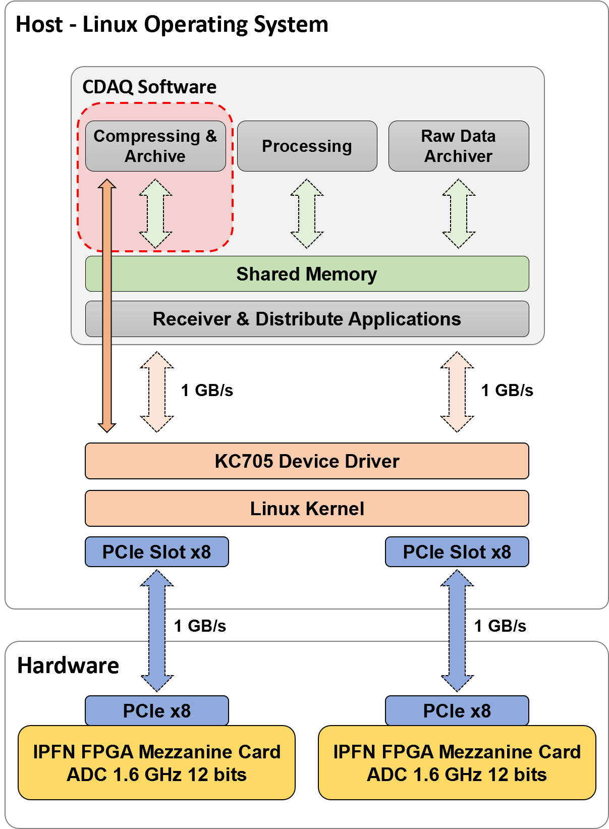
Interfacing between the hardware and high-level applications is installed the Linux device driver, supporting data transfers up to 1.6 GB/s per board. The Control and Data Acquisition (CDAQ) software includes a shared memory layer to distribute the acquired real-time data across the client applications when several clients need to use the data at same time.
At the application level, software modules were developed for:
-
•
Real-time data compression to reduce the data size.
-
•
Data pulse processing for energy and particle discrimination.
-
•
Real-time raw archiving for test purposes with low data rate acquisitions.
In the presented tests, the compression application was directly connected to the device driver for evaluating its performance limit.
The introduction of the shared memory layer should not affect performance since the approach to read the data from the shared memory must be, in the worst case, as fast as the direct reads from the device drive.
II-A Software Architecture
Fig. 2 presents the compression application software architecture and its interface to the device driver. The compression application is based on the task farm algorithm approach with a master thread that launches a poll of threads with a configured number of worker threads.
The device driver implements a kernel thread with an internal circular buffer to store in real-time the data transferred from the hardware, until it is read from the consumer applications. There are two implemented pointers for the circular buffer (read pointer and write pointer) to control the read operations from the consumer applications and checks data loss between the device driver and the consumer applications. Additionally, the device driver implements algorithms to check the data loss between the hardware and device driver.
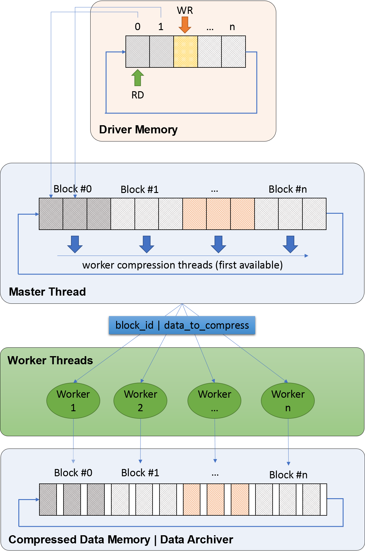
The master thread reads the available data from device driver in real-time, packs it into data blocks with configurable data size and distributes it across the configured number of worker threads. Each data block is tagged with an id to be used by the worker threads to store the compressed data in the correct position of a shared buffer between worker threads. The work balance algorithm distributes the next block to be compressed to the first available core in the pool but other options can be used.
The worker threads implement the compression algorithm and are responsible for the parallel compression in real-time. In the present tests, the worker threads store the compressed data in a memory buffer but can deliver it through the network directly to the data archiver.
The device driver, master thread and worker threads run in isolated cores (detached from the kernel scheduling, preventing its usage by the operating system), taking advantage of the CPU affinity feature, which is the ability to direct a specific task, or process, to use a specified core.
III Preliminary Tests
To identify the achieved compression speed, compression ratio and space-saving with different configurations of the LZ4 algorithm several tests are done using the LZ4 default and LZ4 HC. In the LZ4 default an acceleration option can be configured to get a better compression speed compromising the compression ratio. On the LZ4 HC, a high compression derivative of LZ4, the compression level can be configured to improve the compression ratio compromising the compression speed.
The input data for these tests was collected with real radation sources in Frascatti Neutron Generator (FNG) during the tests in January 2018 and from a waveform generator simulating a gamma ray type signal as input to compare different signal types. The acquisition was configured with a pulse width of 128 samples, producing 256 MB/s throughput.
Table I presents the LZ4 default compression tests comparing the different sources and acceleration factors. The results suggest that the accelerations with even number (2, 4, 6, 8, 10 and 12) have a better relation between compress speed and compress ratio. However, the acceleration with factor 1 has the better compression ratio.
| Acceleration | FNG | PULSE SIGNAL | ||||
| Speed (MB/s) | Ratio | Space Saving | Speed (MB/s) | Ratio | Space Saving | |
| 1 | 337.25 | 1.38 | 27.63% | 317.39 | 1.44 | 30.75% |
| 2 | 419.15 | 1.34 | 25.22% | 400.51 | 1.40 | 28.31% |
| 3 | 409.85 | 1.32 | 24.43% | 385.96 | 1.35 | 26.04% |
| 4 | 475.87 | 1.29 | 22.15% | 470.52 | 1.31 | 23.44% |
| 5 | 448.09 | 1.28 | 21.82% | 429.99 | 1.29 | 22.72% |
| 6 | 523.47 | 1.25 | 19.97% | 524.37 | 1.26 | 20.53% |
| 7 | 492.34 | 1.25 | 19.84% | 477.26 | 1.25 | 19.96% |
| 8 | 575.08 | 1.21 | 17.41% | 603.26 | 1.20 | 16.75% |
| 9 | 539.40 | 1.21 | 17.53% | 533.68 | 1.20 | 16.97% |
| 10 | 600.72 | 1.19 | 16.05% | 662.61 | 1.17 | 14.56% |
| 11 | 566.24 | 1.19 | 16.13% | 580.35 | 1.18 | 15.33% |
| 12 | 659.45 | 1.15 | 13.32% | 727.40 | 1.15 | 12.79% |
Table II presents the LZ4 High Compression (HC) tests comparing the different sources and compression levels. Using the 256 MB/s of data throughput with up to 8 CPU cores running in parallel, only the first 3 compression levels can be used without missing data. The results present a better space saving than in the LZ4 default but compromising significantly the compression speed.
| Compression Level | FNG | PULSE SIGNAL | ||||
| Speed (MB/s) | Ratio | Space Saving | Speed (MB/s) | Ratio | Space Saving | |
| 1 | 89.39 | 1.54 | 35.22% | 101.87 | 1.56 | 36.06% |
| 2 | 73.07 | 1.62 | 38.20% | 83.31 | 1.63 | 38.56% |
| 3 | 55.28 | 1.69 | 40.67% | 58.79 | 1.71 | 41.40% |
| 4* | 40.97 | 1.74 | 42.62% | 32.23 | 1.79 | 44.15% |
| 5* | 30.76 | 1.78 | 43.95% | 20.70 | 1.86 | 46.24% |
| 6* | 23.25 | 1.81 | 44.82% | 13.00 | 1.91 | 47.55% |
| 7* | 17.84 | 1.83 | 45.33% | 9.96 | 1.93 | 48.06% |
| 8* | 14.58 | 1.84 | 45.54% | 9.78 | 1.92 | 47.96% |
| 9* | 13.75 | 1.84 | 45.59% | 9.35 | 1.93 | 48.07% |
| 10* | 12.47 | 1.84 | 45.63% | 9.31 | 1.93 | 48.17% |
| 11* | 9.66 | 1.86 | 46.28% | 7.58 | 1.96 | 48.88% |
| 12* | 9.60 | 1.86 | 46.28% | 7.52 | 1.96 | 48.93% |
Table III presents the theoretically number of needed cores to compress 1 GB/s of data throughput in real-time with different LZ4 default acceleration factors and different LZ4 HC compression levels.
| LZ4 Default | LZ4 HC | |||
| Acceleration | Cores | Compression Level | Cores | |
| 1 | 4 | 1 | 13 | |
| 2 | 3 | 2 | 16 | |
| 3 | 3 | 3 | 22 | |
| 4 | 3 | 4* | 33 | |
| 5 | 3 | 5* | 49 | |
| 6 | 2 | 6* | 69 | |
| 7 | 3 | 7* | 84 | |
| 8 | 2 | 8* | 107 | |
| 9 | 3 | 9* | 113 | |
| 10 | 2 | 10* | 115 | |
| 11 | 2 | 11* | 134 | |
| 12 | 2 | 12* | 136 | |
Using the LZ4 default algorithm there is no difference in the needed cores between the acceleration levels 2 and 5, but the space saving reduces 5%. Using the compression level 1, the space saving is increased 2% but one more core is need.
The LZ4 high compression variant usage is not possible because it needs at minimum 13 available cores (10 more than LZ4 default) to improve the space saving in 6%.
The tests also confirm compressing speed and ratio similarities between the acquired signals in the real environment and signals from the waveform generator.
IV Tests and Results
The tests were based in a pulse type signal from a waveform generator simulating a gamma-ray distribution. The acquisition tests have different pulse width configurations to produce distinct acquisition data rates up to 1.5 GB/s. Each acquisition test has 60 minutes, in agreement with the ITER long pulse acquisitions. All tests have 10 MB of data block size to compress, except the tests to verify the impact of the usage of other block sizes.
To compress data with maximum compression ratio available, the LZ4 default algorithm with acceleration factor 1 was selected.
IV-A Number of Cores
Table IV presents the relation between the data loss and number of cores for different data acquisition rates.
| Data Rate (MB/s) | Number of Cores | |||||
| 1 | 2 | 3 | 4 | 5 | 6 | |
| 128 | 0.00% | - | - | - | - | - |
| 256 | 0.00% | - | - | - | - | - |
| 512 | 40.68% | 0.00% | - | - | - | - |
| 768 | 61.06% | 22.33% | 0.00% | - | - | - |
| 1024 | 69.38% | 38.83% | 8.80% | 0.00% | - | - |
| 1536 | 79.58% | 59.27% | 39.09% | 19.12% | 4.32% | 0.00 |
Based on the results, the minimum number of needed cores per data acquisition rate with no data loss are:
-
•
1 core to compress until 256 MB/s
-
•
2 cores for 512 MB/s
-
•
3 cores for 768 MB/s
-
•
4 cores for 1 GB/s
-
•
6 cores for 1.5 GB/s.
These results are inside the range of the preliminary results for acceleration level 1, which have a compression speed 300 MB/s per core.
IV-B CPU Usage
The used CPU supports Intel® Hyper-Threading Technology, providing 12 logical cores for the operating system, based on their 6 physical cores. This architecture can result in slightly differences to tests with 12 dedicated cores that can produce small improvements.
Table V presents average core usage of the dedicated cores to the master and worker threads for each acquisition data rate.
| Pulse Width (Number of Channels) | Data Rate (MB/s) | Number of Cores | Worker Threads | Master Thread |
| 32 (1 Ch) | 128 | 1 | 37.00% | 0.54% |
| 64 (1 Ch) | 256 | 1 | 81.00% | 0.59% |
| 128 (1 Ch) | 512 | 2 | 84.00% | 0.57% |
| 256 (1 Ch) | 768 | 3 | 86.00% | 0.56% |
| 128 (2 Ch) | 1024 | 4 | 82.00% | 2.75% |
| 256 (2 Ch) | 1536 | 6 | 88.00% | 25.64% |
IV-C Compression Statistics
Table VI summarizes the compression results of the tests with different pulse widths.
| Pulse Width (Number of Channels) | Data Rate (MB/s) | Ratio | Space Saving | Compression Speed (MB/s) | ||
| Avg | Min | Max | ||||
| 32 (1 Ch) | 128 | 1.33 | 24.91% | 353.73 | 342.20 | 355.63 |
| 64 (1 Ch) | 256 | 1.43 | 29.97% | 317.43 | 307.80 | 319.10 |
| 128 (1 Ch) | 512 | 1.55 | 35.61% | 302.76 | 294.87 | 304.23 |
| 256 (1 Ch) | 768 | 1.63 | 38.47% | 297.74 | 280.02 | 299.04 |
| 32 (2 Ch) | 256 | 1.33 | 25.07% | 352.35 | 340.90 | 353.41 |
| 64 (2 Ch) | 512 | 1.44 | 30.54% | 321.14 | 312.86 | 322.40 |
| 128 (2 Ch) | 1024 | 1.54 | 35.17% | 310.64 | 212.45 | 313.25 |
| 256 (2 Ch) | 1536 | 1.60 | 37.36% | 284.58 | 196.20 | 313.33 |
IV-D Block Sizes
Table VII presents the test of different data block sizes with same input signal and configurations (1 channel with pulse width 128 and acquisition data rate of 512 MB/s).
| Block Size (MB) | Ratio | Space Saving | Compression Speed (MB/s) | ||
| Avg | Min | Max | |||
| 1 | 1.52 | 34.14% | 296.86 | 269.57 | 298.93 |
| 10 | 1.55 | 35.61% | 302.76 | 294.87 | 304.23 |
| 100 | 1.54 | 35.06% | 305.43 | 304.82 | 306.06 |
| 200 | 1.52 | 34.29% | 306.36 | 305.34 | 306.77 |
The results suggest that data block size did not improve the space saving, however the standard deviation of the compression speed during the pulse is reduced.
IV-E CPU and Memory Usage
Fig. 3 presents the CPU and memory usage during 3 acquisitions from one board during 10 seconds with 1024 MB/s of acquisition data rate. There are two dedicated cores for the operating system, one isolated core for the device driver thread, one isolated core for the compression master thread and four isolated cores for the compression worker threads. The allocated memory is around 6 GB in run-time to the data buffers.
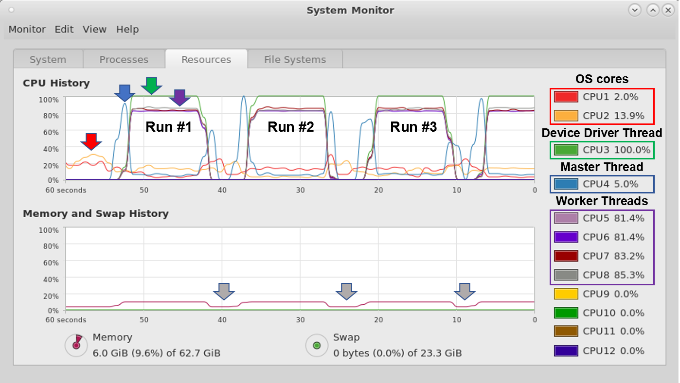
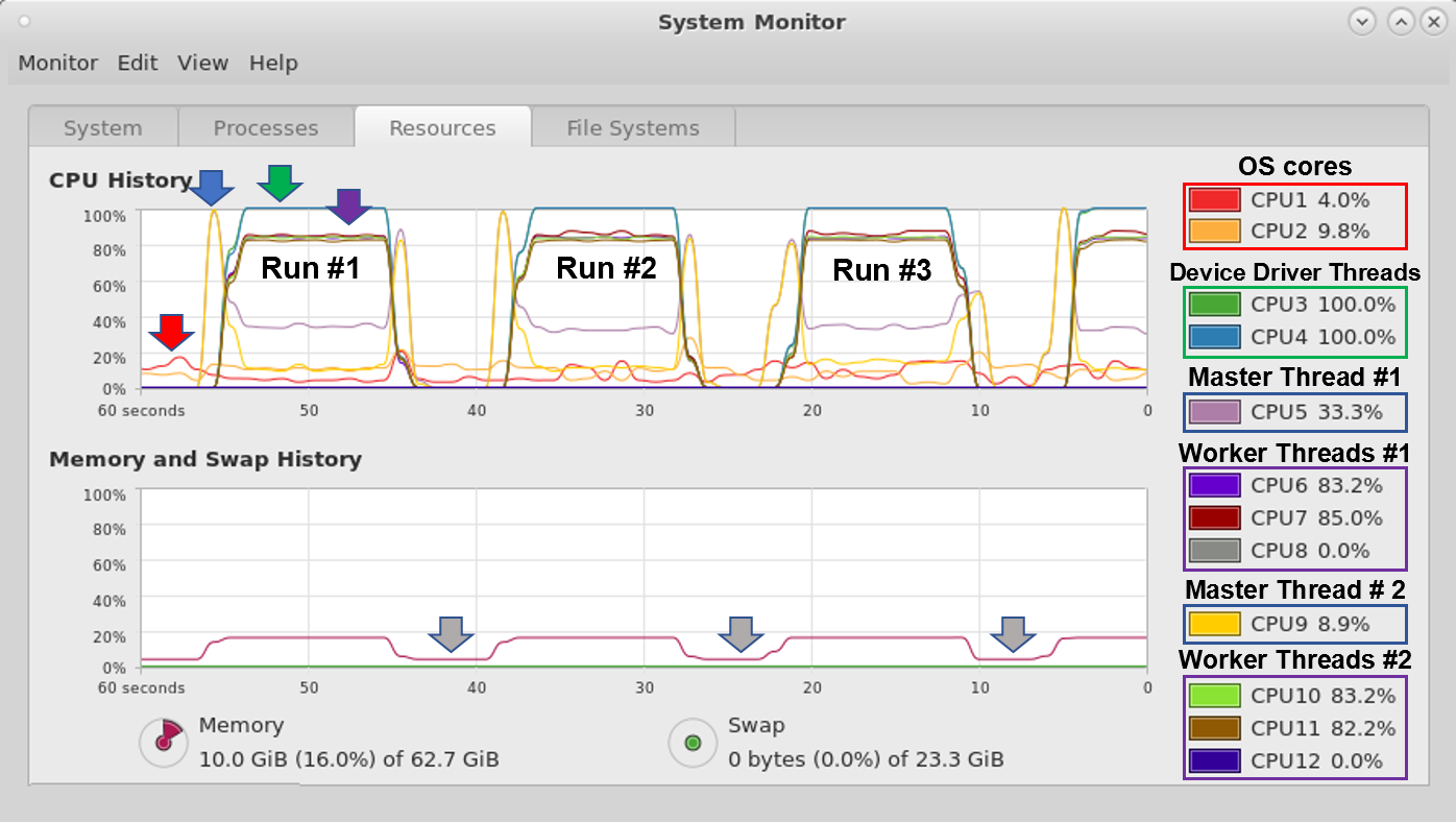
Fig. 4 present the CPU and memory usage during 3 acquisitions from two boards simultaneously during 10 seconds with 512 MB/s of data acquisition rate per board. There are two dedicated cores for the operating system and each board uses five isolated cores (one for the device driver thread, one for the compression master thread and three for the worker threads). The allocated memory is around 10 GB in run-time to the data buffers.
IV-F Relation Between Space Saving and Pulse Width
Fig. 5 depicts the relation between space saving and pulse width for signals using one and two ADCs.
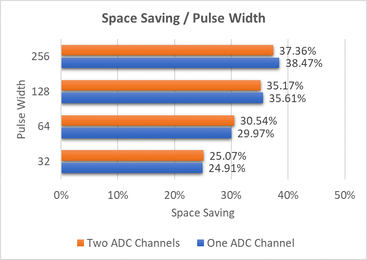
Independently of the ADCs number, a relation between space saving and pulse width can be identified. Using a greater pulse width, the relative space saving increases which can be related with the type of acquired data.
V Conclusions and Future Work
This contribution evaluates the feasibility of data compression implementation in the host PC and contributes to the RNC diagnostic specification.
The presented architecture is scalable and adjustable. The number of worker threads can be configured to comply with different algorithms and data throughput.
The stress tests show a stable solution during 60-minute acquisitions with data acquisition rates up to 1.5 GB/s, using a maximum of 6 worker threads in parallel.
The system was also tested in Fedora Linux 27, kernel 4.16, the community version of Red Hat Linux that supports ITER CODAC system. The results were similar, which validates the developed architecture for future kernel version of Red Hat Linux.
Based on the presented tests, to compress 1 GB/s from one board in real-time, a minimum of 5 cores are needed (1 master and 4 worker threads). Using two boards simultaneously to acquire 1GB/s in each, the system will need 14 cores (2 cores for operating system, 2 cores for the device driver, 2 cores for master thread and 8 cores for the worker threads). There are several commercial CPUs that support this architecture.
The preliminary tests with two boards simultaneously showed a possible performance decreasing. Acquiring 512 MB/s the system needs 3 cores, instead of 2 with a single board. This can be related with the usage of Intel® Hyper-Threading Technology instead of dedicated cores but intensive tests with two hardware modules acquiring simultaneously are scheduled to a future task.
With the tested signals, the maximum achieved space saving with the LZ4 algorithm was between 25% and 40%. Changes on signal configuration can influence the compress ratio.
In the future, the data compression can be implemented in the GPU or FPGA to compare the results with the host PC. There are some possible advantages to be tested but for the FPGA implementation, a new data path to the host is needed, once the processing algorithms need decompressed data in real-time. This increases the data transfer throughput between FPGA and host PC, which can be a demanding task for the Linux device driver.
Acknowledgment
This manuscript is in memory of Professor Carlos Correia who is no longer among us.
References
- [1] D. Marocco et al., Neutron measurements in ITER using the Radial Neutron Camera, J. Instrum. 7 (2012) C03033.
- [2] D. Marocco et al., System level design and performances of the ITER radial neutron camera, Proc. 26th IAEA Fusion Energy Conf., Japan, 2016
- [3] M. Riva et al., High-Priority Prototype Testing in Support of System-Level Design Development of the ITER Radial Neutron Camera, IEEE Transactions on Plasma Science, 46 (2018), 1291-1297.
- [4] R.C. Pereira et al., Real-Time Data Acquisition and Processing System Design for the ITER Radial Neutron Camera, Proc. 1st EPS Conference on Plasma Diagnostics, Italy, 2015.
- [5] R.C. Pereira et al., Real-Time data acquisition Prototype proposal of the ITER radial neutron camera and gamma-ray spectrometer, Fusion Eng. Des. 123 (2017) 901-905.
- [6] N. Cruz et al., Real-time software tools for the performance analysis of the ITER Radial Neutron Camera, Fusion Eng. Des. 123 (2017) 1001-1005.
- [7] Yann Collet et al., LZ4 - Extremely Fast Compression algorithm, https://lz4.github.io/lz4/ Accessed: 2018-06-07
- [8] M. Kuhn et al., Data Compression for Climate Data, Supercomputing Frontiers and Innovations: an International Journal, 3 (2016),75-94
- [9] M. Bartík et al., LZ4 compression algorithm on FPGA, 2015 IEEE International Conference on Electronics, Circuits, and Systems (ICECS), Cairo, 2015, pp. 179-182.
- [10] W. Liu et al., Data Compression Device Based on Modified LZ4 Algorithm, IEEE Transactions on Consumer Electronics, 64 (2018), 110-117
- [11] R. A. Patel et al., Parallel lossless data compression on the GPU, Innovative Parallel Computing, San Jose, CA, 2012, pp. 1-9.
- [12] A. Ozsoy et al., CULZSS: LZSS Lossless Data Compression on CUDA, 2011 IEEE International Conference on Cluster Computing, Austin, TX, 2011, pp. 403-411
- [13] A. Ozsoy et al., Pipelined Parallel LZSS for Streaming Data Compression on GPGPUs, 2012 IEEE 18th International Conference on Parallel and Distributed Systems, Singapore, 2012, pp. 37-44
- [14] E. Sitaridi et al., Parallel Lossless Compression using GPUs, GPU Technology Conference (GTC’14) San Jose, CA, 2014
- [15] N. Cruz et al., The design and performance of the real time software architecture for the ITER Radial Neutron Camera, 21st IEEE Real Time Conference, Colonial Williamsburg, USA, June 2018
- [16] A. Fernandes et al., FPGA code for the data acquisition and real-time processing prototype of the ITER Radial Neutron Camera, 21st IEEE Real Time Conference, Colonial Williamsburg, USA, June 2018