Theoretical and Simulation Study of Comb Electron beam and THz generation
Abstract
A compact accelerator based super-radiant THz source is under development at Inter University Accelerator Centre (IUAC), New Delhi. The facility is based on the principle of pre-bunched Free Electron Laser (FEL) which will produce THz radiation in the range of 0.18 to 3 THz from a modulated electron beam. A photocathode electron gun will generate a short train of micro-bunches (a comb beam) driven by a fiber laser system capable of producing multi micro-pulse laser beam with variable separation ( comb laser pulse). Upon acceleration, the electron beam will be injected in to a compact undulator magnet tuned to the same frequency as the separation of the electron micro-bunches. The paper discusses the process of enhancement of super-radiant emission of radiation due to modulation in the comb beam and the conditions required to achieve maximum enhancement of the radiation power. The feasibility study of generating a comb beam at the photocathode and its transport through the beamline while preserving its temporal structure has been reported. To evaluate the characteristics of the radiation emitted from the comb beam, a based particle tracker and Liẽnard-Wiechert field solver has been developed. The conceptual understanding of the emission of radiation from comb beam is shown to conform with the numerical results. The code has been used to calculate the radiation pulse energy emitted into the central cone of undulator for various comb beam configurations.
I Introduction
The advent of the THz sources and the advantages of THz time-domain spectroscopy over the Far Infra-Red (FIR) Fourier transform spectroscopy has placed the scientific world ”At the Dawn of the New Era in THz Technology” Hosako2007. Until recently, the availability of THz sources was limited and the region between 0.1 THz to 10 THz was called as ’THz Gap’. However, with the advancements in the schemes of producing THz sources and its indispensable futuristic roles in understanding plethora of physical, chemical and biological processes, the THz Gap is firming its position as bridge between the fundamental sciences e.g. non-linear optics Kono1997; Rojan2017; Danielson2007, condensed matter physics Zalden2016; Ulbricht2011, non-linear spectroscopy Jewariya2010, selective control of magnetic properties of materials Kovalev2018 etc. and the real world applications like characterization of materials Ferguson2002, non-invasive imaging Knap2009, national security Shen2005; Zandonella2003; Stoik2008, THz communication Koenig2013, monitoring of industrial processes Skryl2014; Duling2009, biomedical applications Yu2012 etc.
The required boost to the development of THz sources is attributed to immense research activities in the fields of Photo-conductive switches Auston1975; Auston1984; You1993; Budiarto1996, Optical Rectification Bass1962; Yang1971; Rice1994, Accelerator based Coherent Synchrotron Radiation (CSR) Michel1982; Nakazato1989; Bocek1996; Zhang2012; Perucchi2013; Green2016; Nasse2013; Gensch2008 or Coherent Transition Radiation (CTR) Casalbuoni2009; Hoffmann2011a; Wu2013; Carr2002, Quantum Cascade Lasers Williams2007 and Laser Induced Air Plasma Xie2006 based devices. Amongst the variety of THz sources, Photoconductive switches and Optical Rectification techniques are most commonly used and historically important. Photoconductive switches are based on biased semiconductor devices (Auston Switches Auston1975; Auston1984 ) which can be thought of as loaded capacitor Hoffmann2011. If a femtosecond laser pulse is incident on the switch, the stored electrostatic energy is released in the form of ultrashort, high bandwidth, single-cycle THz radiation having pulse energies in the range of few femtojoule per pulse. Much higher THz pulse energies ( 0.8 J) using photo-conductive switches were obtained by You et al. by applying high-bias voltage across GaAs crystalline wafers and exciting the switch by 120 fs, 770 nm laser pulses from a Ti:Sapphire chirped-pulse amplifier system You1993. The most common mechanism to generate single cycle (broadband) or multi-cycle (narrowband) THz pulses having J pulse energies is to use the Optical Rectification (OR) technique Yang1971 which is based on inducing instantaneous second-order nonlinear susceptibility (and therefore non-linear time-dependent polarization ) in an organic or inorganic semiconductor crystal by using an intense broadband femtosecond pump pulse. Due to second-order non-linear processes inside the crystal, intrapulse difference frequency generation (DFG) occurs; resulting in a rectified THz pulse Hoffmann2011; Lee2000. The most commonly used crystal for OR is ZnTe while other crystals e.g. GaP, GaAs, DAST, LiNb are becoming increasingly popular. Recently, several groups have shown that OR techniques can be used to generate THz pulses with high fields (1 MV/cm) Hirori2011; Oh2014; Hebling2008, high pulse energies Yeh2007 and multi-cycle narrowband THz pulses Lee2000.
Although THz sources based on Photoconductive switches or OR are more accessible, less bulky and commercially available; accelerator based THz sources offers much higher brilliance, pulse energies, tunability, repetition rates and offer both broadband (from bending magnets) and narrowband THz pulses (from undulators) Stojanovic2013. The possibility of intense coherent emission of radiation from short bunches of relativistic particles in a storage ring was first mentioned by Michel in 1982 Michel1982 and observed by Nakazato at Tohoku in 1989 Nakazato1989. Over the last two decades, there has been significant improvement in the techniques employed to generate high power narrowband tunable coherent THz pulses from storage rings. K. Holldack et. al have used energy modulated electron beam (’femtosliced’ electron beam) to produce femtosecond broadband THz pulses at BESSY storage ring Holldack2006. J. M. Byrd et al. Byrd2006 at Advanced Light Source has been able to produce temporally and spatially coherent THz pulses using longitudinally and transversally modulated electron beam. They also showed that the electric field of the THz pulses can be tailored by varying the intensity, delay and number of pulses of the slicing laser pulse . Groups at UVSOR at Okazaki, Japan and DELTA in Dortmund, Germany have demonstrated generation of continuously tunable narrowband pulses in the THz and sub-THz regime using laser modulated electron beams Bielawski2008; Ungelenk2017.
In 1979, John M.J. Madey invented FEL Madey1971 and his group successfully demonstrated its operation in 1977 at Stanford Deacon1977. The world’s first FEL working in the THz regime was based on electrostatic accelerator at the University of California, Santa Barbara (UCSB) FEL . The original FEL at UCSB is now replaced with two FELs (MM-FEL and FIR-FEL) and cover the frequency range of 0.12 THz to 4.8 THz Ramian1992. Another electrostatic accelerator based FEL is the Israeli FEL which can operate in continuous wave (cw) or quasi-static mode. The Israeli FEL achieved its first lasing in 1997 at pulsed power mode and provided 1kW of power at 0.1 THz Abramovich1997. The Free Electron Lasers at Jefferson Lab, Virginia (JFEL) Neil2000 and Novosibirsk, Russia (NovoFEL) Knyazev2010 are based on Energy Recovery Linacs (ERL) and have been able to provide infrared (IR) or THz pulses at 1.72 kW and 500 W respectively. Except for ERL based FELs or Electrostatic Accelerator based FELs, cw mode operation of FELs can be achieved in super-conducting linacs only. The FEL at the Electron Linear accelerator with high Brilliance and Low Emittance (FELBE) facility at Helmholtz-Zentrum Dresden-Rossendorf (HZDR) Dresden, Germany has a thermionic gun coupled with two super-conducting linac modules which operates in a cw or quasi cw mode with 15 MHz pulse repetition rate. Using two FELs (U37-FEL and U100-FEL), they are able to cover mid and far infrared regime of electromagnetic spectrum Winnerl2006. Also, TELBE facility at HZDR can produce multi-cycle THz pulses at very high repetition rates. TELBE facility have a thermionic gun based electron injector which can be operated at 13 MHz repetition rate with 100 pC bunch charge to produce THz pulse energy of the order of 1 J and is working on SRF injector based THz source which shall operate at 500 kHz repetition rate with 1 nC bunch charge to produce pulse energies as high as 100 JGreen2016. For a more detailed list of FELs, readers are referred to a review article titled ’Accelerator Sources for THz Science: A Review’ by G.R. Neil Neil2014.
The latest entry to the accelerator based THz sources are the Linac based Super-Radiant THz sources. It is now very well understood that the quality of the emitted radiation from a collection of electrons depends upon the number of electrons in the bunch and the phase-space volume occupied by the electrons in the bunch Gover2005. Intense coherent radiation can be generated from electron bunches if (a) the electron beam bunch length is much smaller than the radiation wavelength () to be generated, (b) the transverse beam size is of the order of and (c) the number of the particles in the bunch is as high as possible. Under these conditions, the radiation power scales as the square of the number of the particles in the bunch Hirschmugl1991. Several groups have used super-radiant electron bunches to produce intense CTR Wu2013; Kung1994; Hoffmann2011a or Coherent Undulator Radiation Green2016 in the THz regime.
In this paper, a compact THz source project at IUAC, named as Delhi Light Source (DLS) Ghosh2017, capable of producing continuously tunable, narrowband, multi-cycle, coherent THz pulses in the range of 0.18 to 3 THz from a train of super-radiant micro-bunches (henceforth called as comb beam) is being presented. In the present approach, we show that train of super-radiant micro-bunches can be produced from a normal conducting photocathode electron gun by temporally modulating the incident photolaser; eliminating the need of a magnetic chicane to compress the electron bunch and reducing the size of the beamline. Further, the flexibility of varying the separation between the micro-bunches, the total number of micro-bunches and the charge per micro-bunch of the comb beam gives an additional advantage to provide tunable frequencies, variable intensities and variable pulse duration of the electromagnetic radiation.
Presently, effort is on to develop the first phase of DLS which is briefly described in Section II. In Section III, the conditions required to enhance the radiation power emitted into the resonant frequency of the undulator by the comb electron beam has been discussed. The results of beam optics calculations done by using the General Particle Tracer (GPT) Geer1996 code has been presented in Section LABEL:BeamOptics. To simulate the emission of the radiation inside the Undulator, a code based on has been developed to track the electron beam inside the Undulator and to compute the radiation emitted by them using the Liẽnard-Wiechert fields Jefimenko1992; Jackson1999. The results of the THz calculations has been presented in Section LABEL:THz_calculations.
II Delhi Light Source: Phase-1
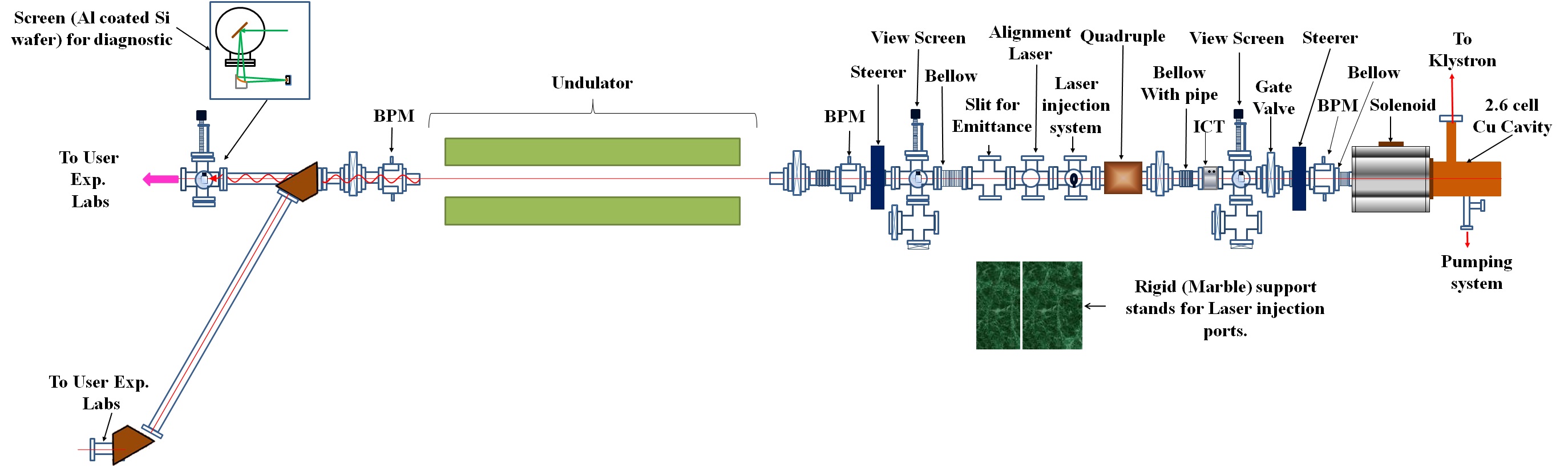
The first phase of Delhi Light Source, is an ongoing project at IUAC to develop a THz radiation source facility. The complete facility will be developed in three phases and the work towards the Phase 1 (layout shown in 1) is presently going on. The aim of the first phase is to develop a compact super-radiant THz source based on normal conducting (OFHC copper) photo-injector for pulsed mode operation Ghosh2017.
The choice of the Laser system for DLS is a Yb doped fiber laser system with an oscillator frequency of 130MHz ( sub-harmonic of the main master clock) and 1030 nm as fundamental wavelength. However, 130 MHz repetition rate will be reduced to 5 MHz to reduce laser pulse loading inside the fiber. At this point it is important to mention that the normal conducting cavity in the Phase-1 of the DLS project will be operated in a low duty cycle mode and therefore the length of the RF window is limited to 3 seconds with 6.25 Hz repetition rate. Thus, in a time window of 3 seconds, 15 laser pulses will be selected. Each of these 15 laser pulses will be passed through two stage burst amplification to increase the laser pulse energy. After this stage, Michelson Interferometer type pulse-divider( based on multi-stage polarised beam splitting with optical delay lines) Aryshev2017; Shevelev2017 will split each of the 15 laser pulses into 2, 4, 8 or 16 micro-pulses. The laser micro-pulses will be then converted from fundamental IR (1030nm) to UV (258nm) before being incident on the photo-cathode to generate the comb electron beam. The carrier envelope of the electron beam is shown in Fig. 2 and the expected pulse energy in a single micro-pulse is given in the Table II . The laser system is being developed in collaboration with KEK, Japan.

| Energy | ||||
|---|---|---|---|---|
| Number | FWHM | |||
| Cathode | Max. Charge /micro-bunch | |||
| (pC) | ||||
| 0.1 | ||||
| (Steady State) | 1-16 | 200 | 200 |
The accelerating structure for the Phase-1 of DLS is a 2.6 cell, S-band (2860 MHz) normal conducting resonant cavity which will be powered by a 25 MW high power RF system consisting of Klystron and Modulator. The cavity is coupled with a solenoid to compensate for the growth in emittance. The temporal structure of the comb electron beam will be identical to the comb laser pulses at the cathode and therefore; the accelerating field strength at the cathode surface must be high enough to preserve the modulation of the electron beam through the initial stages of the acceleration until reaching relativistic velocities. The maximum energy of the comb beam is expected to be 8 MeV.
The comb beam will be injected into a planar undulator to produce coherent THz radiation. Inside the undulator, the wave packets emitted from individual micro-bunches inside the same micro-bunch train will interfere constructively if the separation between the micro-bunches is made equal to the wavelength of the radiation. If the coherence condition is satisfied then the intensity of the emitted Coherent Undulator Radiation Neuman2000; Bocek1996 will be proportional to the square of the total number of electrons in the multi micro-bunch structure of the electron beam Hirschmugl1991. By adjusting the electron energy and changing the gap of the undulator magnet, the wavelength of the radiation frequency can be adjusted in the range of 0.18 to 3.0 THz by following the equation Madey1971; Motz1951:
| (1) |
where =0.934 is the undulator parameter, is the undulator period, is the peak magnetic field on the axis of the undulator, is the relativistic factor for the electron and is the angle of observation of the radiation.
III Theory of Coherent Emission of Radiation from the Comb Beam
It is well understood that an accelerating charged particle emits electro-magnetic radiation whose power varies remarkably with the particles energy. The electric and magnetic fields of the emitted radiation can be found using the Liẽnard-Wiechert formulation for the fields of a point particle of charge q, which is given as Jefimenko1992; Jackson1999:
| (2a) | |||
| (2b) | |||
where R = r - r is the distance of the observation point (r) from the source of radiation (r), = R/R is the unit vector pointing from source of radiation to the observation point, , are the velocity and acceleration of the particle respectively, evaluated at retarded time .
The Liẽnard-Wiechert fields can be expressed in the frequency domain by evaluating the Fourier Transform of Eq. 2. Under the approximation that the observation point is extremely far from the source of the radiation (r <<r); we can approximate the unit vector pointing from the electron to observer as r/r. This approximation allows us to write the result of Fourier Transform of the radiation term (second term in Eq.2(a)) as:
| (3) |
where and k= is a constant defined for electrons.
If instead of a single electron, a bunch of electrons is considered; then the total electric field of the emitted radiation wavepacket is given by the sum of the electric fields emitted by individual electrons:
| (4) |
Following Hirschmugl Hirschmugl1991, if we assume that all the electrons move with same velocity i.e. , the coordinate of the j particle with respect to the centre of mass (r) of the bunch is given by (r) and the distance of the observer from the centre of mass of the bunch is much larger than the bunch length ( ); then the summation in Eq. 4 can be written as:
| (5) |
The experimentally measurable quantity is the intensity of the radiation which depends on the square of the amplitude of the electric field. From Eq. 5, the amplitude of the total radiation wave packet, corresponding to a particular frequency , emitted by a bunch will be:
| (6) |
Now, if we define the bunching factor or form factor Hirschmugl1991 as
| (7) |
and the integral (the detailed solution of this integral can be found in G.DattoliA.Renieri1993) as
| (8) |
then Eq. III becomes:
| (9) |
From the above equation, it is clear that the intensity of radiation emitted into a particular mode is directly dependent on the bunching factor (corresponding to the same mode). If the bunch length (which can be approximated as two times the position of the electron farthest from the centre of mass) of the beam is extremely small compared to the wavelength of the emitted radiation (, then the entire bunch is approximated as a point source of radiation; resulting in maximum possible intensity of radiation. The coherence effects due to this condition was initially termed as super-bunching Michel1982 and has since been studied and observed by several authors Williams1989; Nakazato1989; Deacon1977; Billinghurst2013.
The above discussion can be further extended to find the electromagnetic fields of a radiation wavepacket emitted by a comb beam. Let us consider a comb beam in which there are micro-bunches having electrons in each micro-bunch, the position of electron (with respect to the centre of mass) in the micro-bunch is given by and that the centre of mass of micro-bunch follows the trajectory given by . The electric field of the wavepacket emitted by this beam will be given by:
where is the velocity of the micr-obunch. In the above expression for the electric field, care needs to be taken to separate the integral from the summation. Let the trajectory followed by the centre of mass of the first micro-bunch and its velocity be given by and respectively. We assume that the particles of all the micro-bunches are ultra-relativistic and have same velocity i.e. ≃βΔr_mr_c,mr_cΔr_mB(ω)B_avg 1.Ifthebunchstructureofallt