Strategies to cure numerical shock instability in HLLEM Riemann solver
Abstract
The HLLEM scheme is a popular contact and shear preserving approximate Riemann solver for cheap and accurate computation of high speed gasdynamical flows. Unfortunately this scheme is known to be plagued by various forms of numerical shock instability. In this paper we present various strategies to save the HLLEM scheme from developing such spurious solutions. A linear scale analysis of its mass and interface-normal momentum flux discretizations reveal that its antidiffusive terms, which are primarily responsible for resolution of linear wavefields, are inadvertently activated along a normal shock front due to numerical perturbations. These erroneously activated terms counteract the favourable damping mechanism provided by its inherent HLL-type diffusive terms and trigger the shock instability. To avoid this, two different strategies are proposed for discretization of these critical flux components in the vicinity of a shock: one that deals with increasing the magnitude of inherent HLL-type dissipation through careful manipulation of specific non-linear wave speed estimates while the other deals with reducing the magnitude of these critical antidiffusive terms. A linear perturbation analysis is performed to gauge the effectiveness of these cures and estimate von-Neumann type stability bounds on the CFL number arising from their use. Results from classic numerical test cases show that both types of modified HLLEM schemes are able to provide excellent shock stable solutions while retaining commendable accuracy on shear dominated viscous flows.
1 Introduction
Computation of high speed gasdynamical flows has benefited tremendously from the development of various approximate Riemann solvers for the Euler system of equations. Although most of these schemes are designed to capture nonlinear waves like shocks and expansion fans, they can be broadly classifed into two groups based on their ability to capture the linear waves like entropy and shear waves accurately. The resulting two classes of approximate Riemann solvers are generally referred to in literature as contact-shear preserving and contact-shear dissipative solvers respectively. Roe scheme [1] is one of the most popular examples of the former category and is widely incorporated in most industry and research codes. However, Roe scheme has several problems like requirement of an entropy fix to resolve sonic expansions, lack of positivity in density and internal energy in near vaccum flows and requirement of the knowledge of full eigen structure of the flux jacobians. On the other hand a popular example of a contact-shear dissipative type is the HLL scheme [2, 3]. Since these are based directly on integral form of conservation laws, they do not require linearizations or complete knowledge of eigenstructures of the Euler system. Consequently, these methods do not suffer from the issues mentioned here that plagues the Roe scheme. However lack of contact and shear ability seriously restricts their applicability to practical problems involving shearing flows, boundary layer flows, flame and material fronts etc [4, 5]. Einfeldt et al [6] proposed an interesting option that combines the advantages of the Roe scheme with that of the HLL scheme called HLLEM scheme. The HLLEM scheme is positivity preserving, contact-shear capturing and does not require an entropy fix. Also it demands knowledge of only the eigenstructure of the linear wavefields of the system.
Unfortunately like other contact-shear preserving Riemann solvers, the HLLEM scheme also suffers from various forms of numerical shock instability during simulations of multidimensional flows which involves regions of strong grid aligned normal shocks. A classic example of such a failure is the Carbuncle phenomenon [7]. A catalogue of such failures can be found in [8]. Benign perturbations in the initial conditions are rapidly amplified in the numerical shock region leading to spurious solutions. Most commonly, these instabilities manifest as oscillations in the shock profile, polluted after shock values, growth in error norms in case of steady state problems and in extreme cases complete breakdown of the solution.
Although there is still no agreement on the exact cause of these spurious solutions, many authors suggest that lack of cross-flow dissipation provided by the contact-shear preserving Riemann solvers along the shock front could be a major trigger [9, 10]. A loss in overall dissipation for a contact-shear preserving scheme in such circumstances are argued to happen due to vanishing of their numerical dissipation terms that corresponds to accuracy on linear waves [10, 11]. On the other hand, a linear wave dissipative scheme like the HLLE does not suffer from this. Many cures for creating a shock stable Roe scheme, for example, are hence based on increasing the component of dissipation corresponding to the linear waves in the overall dissipation matrix [9, 11, 12, 13, 14, 15, 16]. Similarly, in case of the HLLEM scheme, Park et al [17] proposed a control of the antidiffusive terms, which are chiefly responsible for restoring accuracy on linear wavefields, to ensure shock stability. Xie et al [18] showed that merely controlling the antidiffusive terms corresponding to the shear wave could guarantee shock stability. Obayashi et al [19] proposed a Carbuncle free HLLEM scheme based on retaining only its HLLE component in the vicinity of a shock although their scheme could benefit from more rigorous testing.
Recently it was clarified in case of another popular HLL-based contact-shear preserving Riemann solver called HLLC scheme, that the antidiffusive terms, specifically in mass and interface-normal momentum flux discretizations in transverse direction of a shock front are the major triggers for instability [20]. It has been found that the antidiffusive terms present in the HLLC discretization of these critical flux components gets activated in the transverse direction of a numerically perturbed normal shock front and causes a reduction in the magnitude of its inherent HLL-type diffusive terms. The weakened diffusive terms fail to provide requisite damping of perturbations in and variables resulting in unphysical variation of conserved quantity along the shock front and subsequent development of shock unstable solutions. Based on this, the authors suggested an inexpensive shock stable HLLC scheme by simply controlling the antidiffusive terms in these critical flux components using a simple differentiable pressure sensor. An interesting alternative to save the HLLC scheme that does not rely upon controlling the antidiffusive terms was proposed in [21]. It involves a strategy to increase the inherent HLL-type dissipation of this scheme in the vicinity of shock through careful modification of certain nonlinear wavespeed estimates. Since the HLLC scheme and the HLLEM scheme are both derived from the HLL scheme, they share identical HLL-type diffusive terms. Thus, it opens up the possibility of extending these appealing cures developed for the former to the latter provided they share similar instability-trigger mechanism.
In this paper, we first perform a linear scale analysis of the numerical dissipation terms of the HLLEM scheme appearing in the mass and interface-normal momentum flux discretizations in the vicinity of a steady shock front subjected to numerical perturbations with an objective to identify specific terms in its formulation that triggers the instability. Our analysis indicates that the instability in the HLLEM scheme is also promoted due to a weakening of its embedded HLL-type dissipation in the direction parallel to a shock front due to erroneous activation of its antidiffusive terms. Based on these findings, we propose two robust strategies to save the HLLEM scheme from shock instability that are based on methods suggested in [20, 21]. The first method focuses on increasing the inherent HLL-type numerical dissipation existing within the HLLEM scheme. This is achieved by carefully modifying non linear wave speed estimates of this embedded HLLE dissipation. Two multidimensional local solution dependent strategies are discussed to ascertain the quantity of supplementary dissipation to be provided to enhance this HLLE component. The second method focuses on reducing the magnitude of the antidiffusive component of the HLLEM scheme relative to its inherent HLL-type dissipation. A technique of linear perturbation analysis [13] is used to show how these different strategies are able to easily dampen numerical perturbations that may appear in the primitive quantities. Corresponding von Neumann stability bounds on the allowable CFL number for implementation of all of these strategies are also estimated. We also demonstrate through our analysis and numerical examples how simply controlling the antidiffusive terms corresponding to shear waves alone, as suggested in [18], may not suffice to create a shock stable HLLEM scheme. Finally, a suite of first order and second order test cases are used to study the effectiveness of these methods in dealing with shock instabilities.
This paper is organized as follows. In Sec.(2,3) we brief the governing equations and finite volume framework adopted in this paper. Sec.(4) recapitulates the details of the HLLE and the HLLEM schemes that form the basis of our discussion. In Sec.(5) we use a linear scale analysis on the HLLE and HLLEM schemes to identify the specific terms in the HLLEM scheme that triggers the instability. This analysis is supplemented with a linear perturbation analysis that provides insights on the evolution of perturbations of primitive quantities in these schemes. Based on these, we describe strategies to formulate a few shock stable versions of the HLLEM scheme in Sec.(6). The linear perturbation analysis developed earlier is extended to study the behavior of these new shock stable versions in dealing with the perturbations. In Sec.(7) certain classic shock instability test cases are used to demonstrate the robustness of these new formulations. Sec(8) presents some concluding remarks.
2 Governing equations
The governing equations for two dimensional inviscid compressible flow can be expressed in their conservative form as,
| (1) |
where are the vector of conserved variables and x and y directional fluxes respectively. These are given by,
| (14) |
In the above expressions, and stands for density, x-velocity, y-velocity, pressure and specific total energy. The system of equations are closed through the equation of state,
| (15) |
where is the ratio of specific heats. Present work assumes a calorifically perfect gas with . A particularly useful form of the Eq.(1) is the integral form given by,
| (16) |
where denotes a control volume over which Eq.(16) describes a Finite Volume balance of the conserved quantities, and denotes the x and y dimensions of the control volume respectively, denotes the boundary surface of the control volume and denotes an infinitesimally small element on . is the outward pointing unit normal vector to the surface .
3 Finite volume discretization
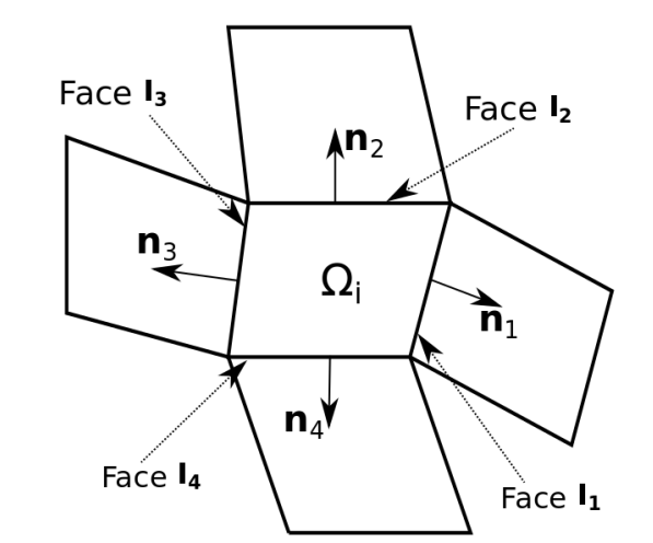
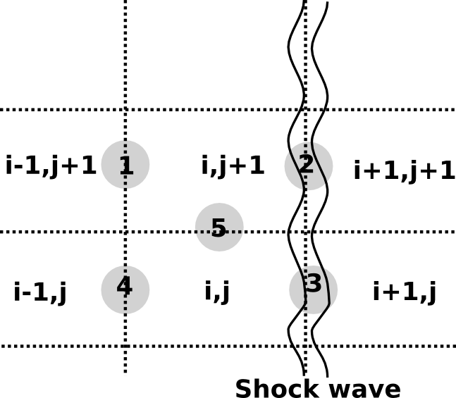
In this paper we seek a Finite Volume numerical solution of Eq.(16) by discretizing the equation on a computational mesh consisting of structured quadrilateral cells as shown in Fig.(1). For a typical cell belonging to this mesh, a semi-discretized version of the governing equation can be written as,
Hence i
| (17) |
where is an appropriate cell averaged conserved state vector, denotes the flux vector at the mid point of each interface while and denotes the unit normal vector and the length of each interface respectively. These are shown in Fig.(1). The interface flux can be obtained by various methods. One of the most popular class of methods to compute this are the approximate Riemann solvers. A conventional two state approximate Riemann solver uses the rotational invariance property of Euler equations to express the term as,
| (18) |
where indicates the initial conditions of a local Riemann problem across interface shared by the cells and . The matrices and are rotation matrices at the interface given by,
| (51) |
where denote the components of the normal vector .
In the next section we briefly describe two approximate Riemann solvers named the HLLE scheme and the HLLEM scheme that can be used to estimate the flux at a given interface. To avoid extra notations, henceforth simply represent the local Riemann flux at any interface with outward pointing normal .
4 Recap of HLLE and HLLEM schemes
The original HLL scheme was devised by Harten, Lax and van Leer [2]. Unlike linearized solver of Roe, the HLL scheme does not require the knowledge of the eigenstructure of the Euler system. Instead it assumes a wave structure consisting of two waves that seperates three constant states. Using the integral form of the conservation laws on this wave structure, the HLL Riemann flux can then be written as,
| (52) |
Here and are the local fluxes at either side of the interface. and are numerical approximations to the speeds of the left most and right most running characteristics that emerge as the solution of the Riemann problem at an interface. It has been shown that under appropriate choice of wavespeeds and , the HLL scheme is both positivity preserving and entropy satisfying [3]. This choice of wavespeeds are given as,
| (53) |
where are the normal velocity across an interface, are the respective sonic speeds and are the standard Roe averaged quantities at the interface [1]. Using these wavespeed estimates, the HLL scheme is also known as the HLLE scheme [3]. For the purpose of this paper, we note that HLLE scheme can also be rewritten as,
| (54) |
where the dissipation can be written as [22],
| (55) |
Although quite accurate in resolution of shocks and expansion fans, the major drawback of HLL scheme is its inability to resolve the contact and shear waves. The loss of accuracy on these waves occur because of the assumption of constant average state between the two waves. Further, it is observed that HLL Riemann solver is free from various forms of numerical shock instability which is generally attributed to its linear wave dissipative nature [13, 23].
Einfeldt et al [6] presented an improved version of the HLLE scheme that can capture the contact and shear waves in addition to retaining the excellent positivity preserving and entropy satisfying property of the original HLLE scheme. Additional accuracy on these waves for HLLE scheme were obtained by explicitly adding necessary antidiffusive terms corresponding to only linear waves. The HLLEM flux can be written as,
| (56) |
with wave speeds still defined by Eq.(53). Here, terms denote respectively the right eigenvectors of the flux jacobians corresponding to the linearly degenerate waves and the strength of these waves obtained by projecting the total jump onto these eigenvectors. Both these quantities are evaluated at the Roe averaged state. These are given as [24],
| (65) |
| (66) |
where operator represents the operation , denotes the tangential component of velocity at an interface and denotes the corresponding Roe averaged quantity. The terms represent coefficients that control the amount of antidissipation being introduced into these waves. An estimate for these that guarantees good accuracy for resolving linear waves are given as [17],
| (67) |
As in the HLLE scheme, we rewrite the HLLEM scheme as,
| (68) |
where the dissipation vector is same as in Eq.(55) and represents the embedded HLL-type dissipation while the antidissipation vector unique to the HLLEM scheme is given as,
| (69) |
In the above expression, the first term denote antidissipation concerning the contact wave while the second term denote that concerning the shear wave. As will be shown in the next section, these terms responsible for accuracy on linear waves will also be responsible for lack of robustness of the HLLEM scheme towards various forms of numerical shock instability.
5 Instability characteristics of HLLE and HLLEM schemes
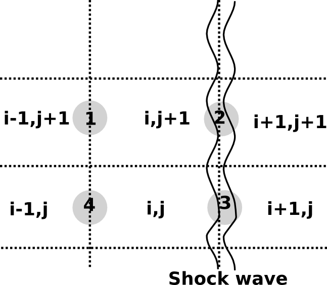
Studies [10, 20] show that unphysical variation of conserved quantity along a numerically computed shock front could be a plausible reason for manifestation of shock instability. Such unphysical variation could occur independently due to undamped perturbations in density () or flow velocity () variables [20]. In case of other shock unstable approximate Riemann solvers like the Roe scheme and the HLLC scheme, the proliferation of these perturbations are known to occur typically due to reduction in overall numerical dissipation caused by inadvertent activation of their antidiffusive terms on interfaces that are not aligned with the shock front [10, 20]. Specifically it has been shown in [20] that activation of antidiffusive terms in the mass and interface-normal flux component discretizations on these crucial transverse interfaces play a major role in triggering of the instability. In this context we would like to closely study the behaviour of the numerical dissipation of the shock unstable HLLEM scheme in comparison to that of the shock stable HLLE scheme to identify the specific terms of the former that participate in the shock instability mechanism. The study is carried out in a simple setting most commonly known to produce shock instability: in the vicinity of a perturbed strong normal shock. For this purpose, consider a y-directional stencil comprising of three candidate cells namely and located within the upstream coloum of cells of an isolated strong normal shock that exists in a steady supersonic flow as shown in Fig.(2).
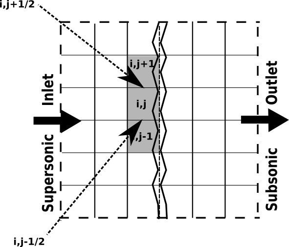
The flow is assumed to happen only in positive x direction. Along the transverse direction (ie. along the y-directional interfaces in this case) in the
vicinity of the shock, the following assumptions can be made without loss of generality:
| (70) |
Our particular concern is the evolution of the conserved quantities and in cell () due to fluxes that cross the interfaces (). While the mass fluxes affect the evolution of quantity , the interface-normal fluxes affect the evolution of quantity . The saw-tooth like perturbations in primitive and conserved variables that are characteristic of a shock unstable solution can be thought to occur due to imbalances in these fluxes only [8]. An evolution equation for these quantities can be written as,
| (71) |
| (72) |
Notice that since there is no primary flow in the y-direction, subsonic fluxes corresponding to the HLLE or HLLEM scheme will be engaged on these interfaces. Ideally, across these interfaces only information regarding pressure would be transmited through the interface-normal momentum fluxes. However if numerical perturbations in flow quantities does exist, then additional unphysical fluxes would occur through these interfaces. The objective then is to see how the HLLEM scheme differ from the HLLE scheme in its treatment of these unphysical fluxes and the perturbed flow quantities that gets convected because of them. In case of the HLLEM scheme, we pay special attention to the role of its antidiffusive terms on the evolution of and quantities.
5.1 Dissipation analysis of the HLLE scheme
Suppose consider that we employ the HLLE scheme to evaluate the fluxes in Eqs.(71) and (72). Then, we are interested in how the numerical dissipation available in the HLLE discretization of these critical flux components affect the evolution of and respectively. Below, we seperately analyze each of them.
5.1.1 Mass flux
A HLLE discretization for and can be written as,
where we have dropped the from the interface index for convenience. The flux difference is then,
Since our interest lies in contrasting the numerical dissipation behaviours of the HLLE and the HLLEM schemes, it suffices to only consider the dissipation component of the flux difference which will be henceforth denoted as . Using the notation , the dissipation component of the above flux difference can be written as,
| (73) |
To introduce the effect of small numerical perturbations that are thought to eventually result in shock unstable solutions, consider the existence of a random numerical perturbations of the order (eg. due to round of errors) in the flow variables that exists during the course of computation in the stencil considered. Then, the following approximations are assumed to hold true on the stencil,
| (74) |
The term can be expanded as . Under the above assumptions is . Assuming and , using Eq.(70) and Eq.(74), Eq.(73) can be simplified as,
| (75) |
Effectively,
| (76) |
Thus in the presence of perturbations of in flow quantities, the HLLE scheme infuses a net dissipation of the same order into the mass flux discretization.
5.1.2 Interface-normal momentum flux
A HLLE discretization for and can be written as,
The dissipation component of the flux difference in this case denoted as will be,
| (77) |
The term can be expanded in terms of the mass flux as and under the assumptions made in Eq.(74) is . Using Eq.(70) and Eq.(74), Eq.(77) can be simplified as,
| (78) |
Which indicates,
| (79) |
Thus in the presence of perturbations of in flow quantities, the HLLE scheme infuses a net dissipation of the same order into the discretization of interface-normal momentum flux in the y-direction.
5.1.3 Role of the activated diffusive terms in the HLLE scheme
It was seen in Sections.(5.1.1) and (5.1.2) that a numerical perturbation in the flow quantities, in the vicinity of a normal shock, tends to activate the dissipation component of the HLLE scheme in both mass and interface-normal momentum flux components. To confirm whether this amount of dissipation suffices to damp out the perturbations in flow variables like , and which affect the quantities and , we resort to a technique of linear perturbation analysis. Mainly, we seek to develop the linearized evolution equations for perturbation in these variables from the approximate evolution equations given in Eqs.(71) and (72) as per the technique provided in [13]. For developing the evolution equation for we additionally utilize an approximate evolution equation of the total energy in transverse direction given by,
| (80) |
In the present work, the steady mean flow is chosen to have normalised state values of , , and . The perturbations in each of these variables denoted as and are introduced as a saw tooth profile superimposed on the steady mean flow. Thus for a typical cell ’j’, the perturbed initial conditions are,
| (81) |
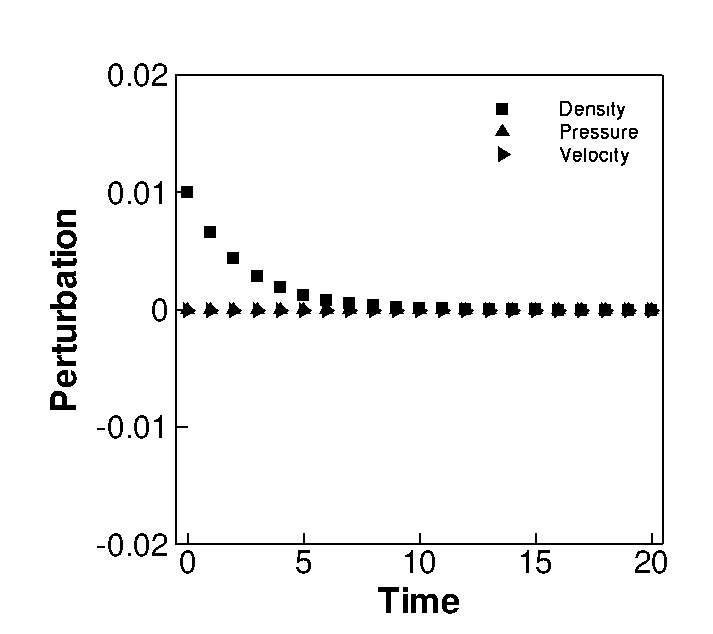
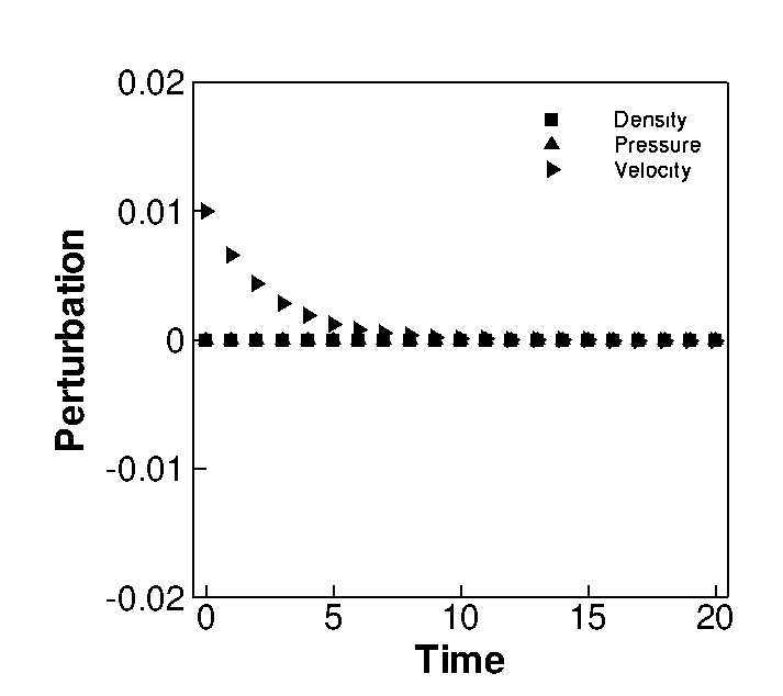
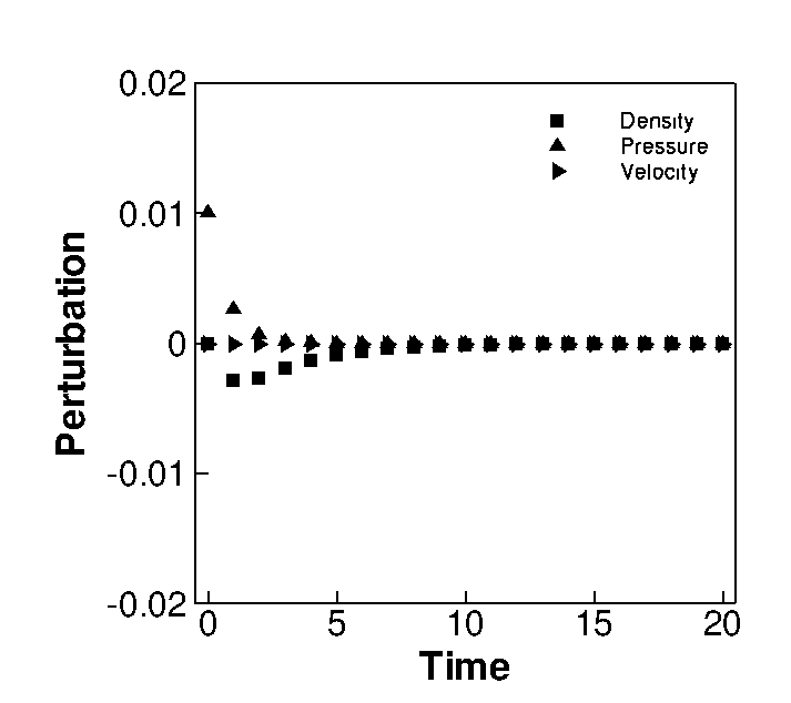
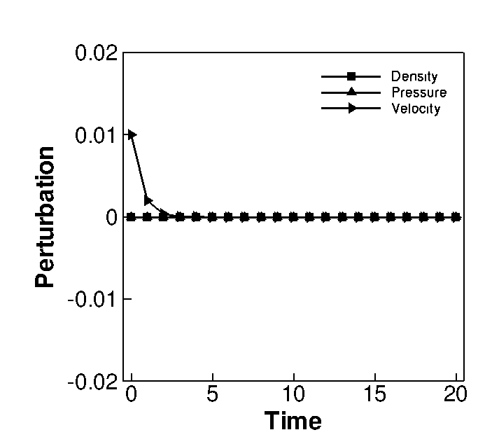
Evolution equations for perturbations in primitive variables , and in case of the HLLE scheme are given in Table 1 where denotes a linearized CFL value. The amplification factors for density, x-velocity and pressure in case of HLLE scheme are respectively. Thus for , any initial perturbation in these flow variables would be effectively damped by the HLLE dissipation. The evolution of these perturbations are plotted in Fig.(3) and is more illustrative of the above discussion. Each plot in Fig.(3) indicate the evolution of all three perturbations: and for a given initial perturbation in only one of those quantities (while setting the other perturbations to be 0). For all the experiments is taken to be 0.2.
| Scheme | Density | Pressure | x-velocity |
|---|---|---|---|
| HLLE | |||
| HLLEM | |||
| HLLEM-SWM-P/E | |||
| HLLEM-ADC | |||
| HLLEMS |
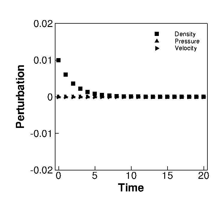
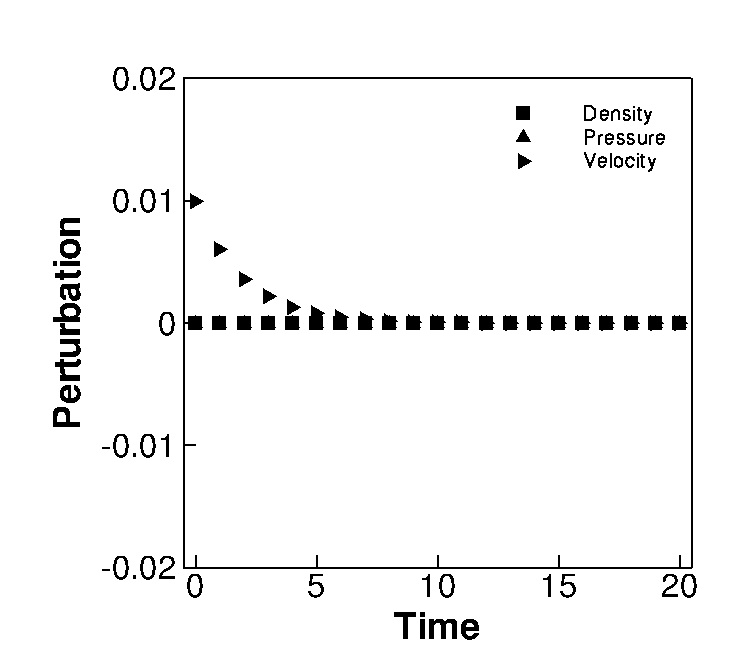
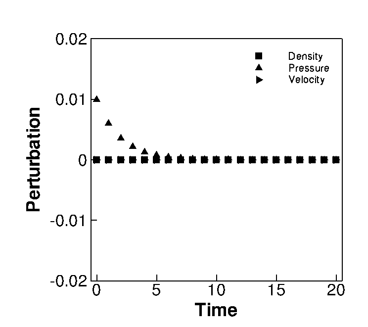
From the behaviour of these evolution equations, it is clear that any perturbation in all three flow variables are attenuated in time by the HLLE scheme. This indicates that the activated dissipative terms of the HLLE scheme as found in Eqs.(76) and (79) are capable of damping any unwanted perturbations that may exist in the course of a numerical computation. This in effect ensures that variation of the conserved quantity along the shock front remains spatially and temporally unvarying and the shock structure is preserved through an accurate Rankine-Hugoniot jump across it.
5.2 Dissipation analysis of the HLLEM scheme
Consider that instead of the HLLE scheme, we use the HLLEM scheme to evaluate the mass and interface-normal momentum fluxes in in Eqs.(71) and (72) at these crucial transverse interfaces. Then, we are interested in how the numerical dissipation provided by the HLLEM scheme differ from that already seen in the HLLE scheme. Below, we seperately analyze each of them. Since HLLEM scheme can be thought of as a combination of the HLLE scheme and antidiffusive terms that are responsible for accuracy on linear waves, we specially study the role of these antidiffusive terms in dealing with these perturbations.
5.2.1 Mass flux
A HLLEM discretization for and can be written as,
| (82) |
| (83) |
The flux difference is then,
| (84) | |||
Since we are interested only in the numerical dissipation provided by the HLLEM scheme, we seek to isolate these terms from the above equation. These terms can be extracted as,
| (85) |
Notice that we have expressed the numerical dissipation of the HLLEM scheme as a combination of HLL-type dissipation (denoted by ) and dissipation arising from its antidiffusive terms. An order of magnitude estimate for has been already presented in Eq.(76). We refer to the second term that arises from antidiffusive component of the HLLEM scheme as . Now we seek an estimate for this term. Firstly notice that using the conditions presented in Eq.(70)and Eq.(74), the wave strength and antidissipation coefficient at each interface can be simplified as,
| (86) |
Using these the term can be estimated to be,
| (87) |
Eq.(87) reveals something interesting. In the presence of numerical perturbations of , it is observed that the antidiffusive terms in the HLLEM massflux discretization is activated and is also of similar to its inherent HLL-type diffusive terms.
5.2.2 Interface-normal momentum flux
A HLLEM discretization for and can be written as,
| (88) |
and,
| (89) |
Flux difference in y-direction is then,
The terms corresponding to numerical dissipation can be extracted as,
| (90) |
We have again expressed the numerical dissipation of the HLLEM scheme as a combination of a HLL-type dissipation (denoted by ) and dissipation arising from the antidiffusive terms. An order of magnitude estimate for has been already presented in Eq.(79). We refer to the second term that arises from the antidiffusive terms of the HLLEM scheme as . By using the conditions presented in Eq.(70)and Eq.(74), this term can be further simplified. Note that under the prescribed conditions, the wave strength . Hence it can be shown that,
| (91) |
Once again, it is observed that numerical perturbations of have activated the antidiffusive terms in the HLLEM interface-normal momentum flux discretization in y-direction. Noticeably, this term is also of similar to its inherent HLL-type diffusive terms.
5.2.3 Role of the activated antidiffusive terms in the HLLEM scheme
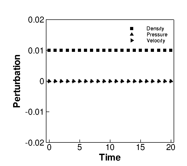
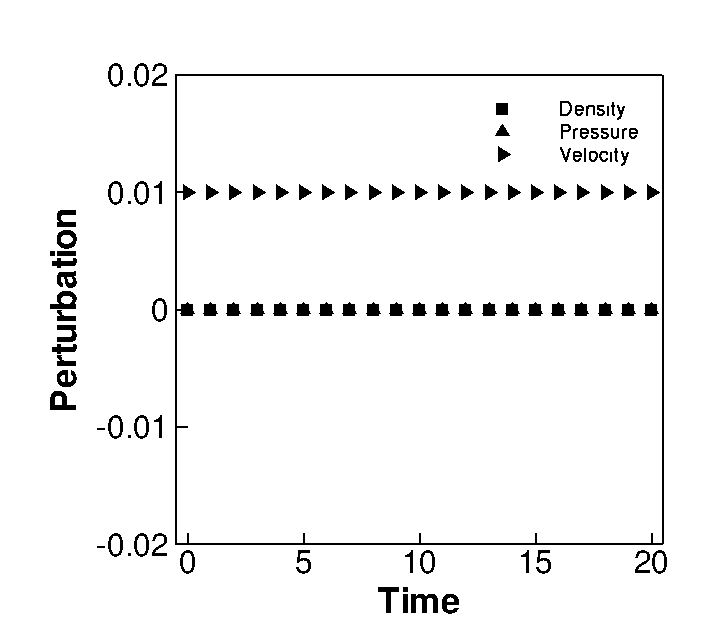
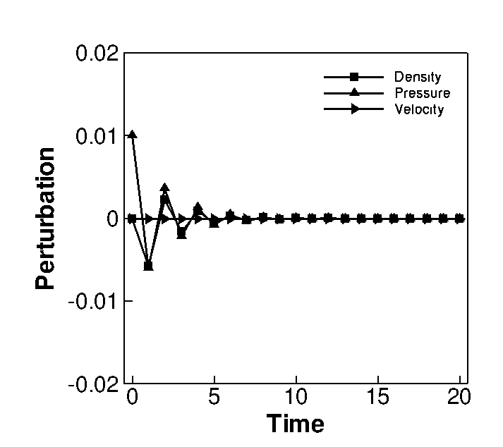
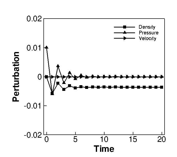
To see the effect of these antidiffusive terms more clearly, we develop the corresponding linearized evolution equations for perturbations in , and for the HLLEM scheme similar to the ones described for the HLLE scheme in section(5.1.3). These are given in Table 1. It is seen from these equations that in case of the HLLEM scheme, the amplification factors for perturbations in , and are respectively. This indicates that the HLLEM scheme is incapable of damping out perturbations in and variables. Additionally it is seen that although there exist a mechanism to damp out perturbations in for , any finite is repeatedly fed into which results in the existence of a residual that is growing with time. The behaviour of these evolution equations are given in Fig.(4). To specifically understand the role of antidiffusive terms in triggering shock instability, we rewrite the evolution equations for perturbations in and variables as,
In these evolution equations, we have clearly distinguished the contribution from the inherent HLL-type diffusive terms and the antidiffusive terms. Suppose during a simulation, random numerical perturbations of exist in flow variables along a strong normal shock wave. From Table (1) we know that the HLLEM scheme has an inherent damping mechanism specifically for pressure perturbations. However, as seen from Eqs.(87) and (91) these perturbations inadvertently activate the antidiffusive terms in the mass flux component and interface-normal momentum flux component on the interfaces transverse to the shock front. These activated terms are also of . The erroneously activated antidiffusive terms introduce additional density and pressure perturbations into the density evolution equation (obtained from mass flux equation) and extra x-velocity perturbation into the x-velocity perturbation evolution equation (obtained from x-momentum equation). These additional terms counteract the dissipative action of the inherently present HLL terms and causes growth in the and perturbations. In fact by their very construction, the antidiffusive terms of the HLLEM scheme are designed to reduce the dissipation associated with its inherent HLL two wave approximation and provide accuracy on linear wavefields. It is known that undamped perturbations in or can independently cause undesirable variations in the conserved quantity along the shock front [20]. Such errors could propagate into other equations due to the nonlinear coupling nature of the Euler equations. These unphysical variations could then be advected into the numerical shock forcing the shock structure to adjust through a typical ’bulge’ or in worst cases a complete breakdown of it as is observed in a shock unstable solution. Thus we see that the mechanism through which the instability is triggered in the HLLEM scheme is analogous to that of the HLLC scheme discussed in [20]. Hence we concieve that cures that were developed for the HLLC scheme in [20, 21] could be extended for the HLLEM scheme. In the following section we explore this possibility and build various versions of shock stable HLLEM scheme.
6 Shock stable formulations of HLLEM scheme
The analyses in the last section reveals that shock instability in the HLLEM scheme could be triggered due to inadvertent activation of its antidiffusive terms in mass and interface-normal momentum flux component discretizations, in the transverse direction of a numerically perturbed shock front, which in turn could weaken its inherently available HLL-type diffusive terms on these components. Based on this understanding, we develop two strategies to save the HLLEM scheme from this failure.
6.1 Shock stable HLLEM scheme based on enhancing inherent HLL-type dissipation
Since the antidiffusive terms present in the mass and interface-normal HLLEM flux discretizations in the transverse direction of a shock front are chiefly responsible for triggering the instability, a straigtforward method to achieve a shock stable HLLEM scheme could be to weaken these antidiffusive terms on these crucial interfaces in the vicinity of a shock. We explore this idea further in Section (6.2). However, an interesting alternative to this philosophy would be to instead focus on increasing the magnitude of its inherent HLL-type diffusion vector on these critical flux components in the vicinity of a shock. It has been shown in [21] that such an extra dissipation can be introduced into the HLL-based schemes by appropriately modifying the nonlinear wavespeed estimates and appearing in the diffusion vector . This has been shown to counter the adverse effect of antidiffusive terms on stability of shock profiles. Hence following correction to the nonlinear wave speed estimates appearing only in the diffusion of these critical flux components is made as,
| (93) |
and in the above equations are obtained from Eq.(53). The term is an appropriate choice of quantity of dissipation to be introduced which is of the order and is a coefficient through which the quantity of introduced into can be controlled. Note that the amount of dissipation to can be varied independently by defining unique for each of them. Both and are by definition nonnegative quantities. We set as 3.5 following conclusions from [21]. Two methods for estimation of that are inspired from the physical nature of the flow are discussed in Sec.(6.1.1) and Sec.(6.1.2). These modified wave speed estimates can be used to enhance the magnitude of the HLLE-type dissipation by incorporating them into the diffusion vector itself. This is achieved by defining a modified diffusion vector for only the mass and interface-normal momentum flux components as,
| (94) |
Although experiments in [20] indicate that treatment of these flux components on the critical transverse interfaces are sufficient to ensure shock stability in case of the HLLC scheme, we observed numerically that this is only a necessary but not a sufficient condition for shock stability in case of the HLLEM scheme. Infact, it was observed that when employing the cure involving the modified diffusion vector , treatment of mass and interface-normal flux discretizations on interfaces in both directions in the vicinity of a shock front: the ones parallel to it and the ones across it ensured shock stability in case of the HLLEM scheme. This may be because the unphysical fluxes that develop along the shock front, due to the unfavourable action of the antidiffusive terms, gets convected into the numerical shock structure at a faster rate than they could be damped through the increased HLL-type dissipation achieved by . Hence, we recommend employing on mass and interface-normal flux discretizations on all interfaces in the vicinity of the shock. Hence this type of modified HLLEM scheme, henceforth referred to as HLLEM-SWM (Selective Wave Modified) can be written as,
| (95) |
Note that the wavespeeds present in the coefficient of the antidissipation vector are left completely unaffected by this modification. This is done purposefully to avoid affecting the linear wave resolution ability of the HLLEM solver. In the coming sections, we discuss two different strategies for estimation of parameter.
6.1.1 Characterisitcs based estimation of
Several choices for estimation of can be designed. Since the purpose of is primarily to increment the value of and locally in the vicinity of a shock wave and tend to zero elsewhere, any viable shock sensor is a good candidate for it. Since shock instability is primarily a multidimensional phenomenon, it is also advisable to have an estimation of that takes this fact into account. This is motivated from the work of Sanders et al [9] who have shown through linear analysis that for upwind schemes in multidimensional computations, a multidimensional shock sensor is more effective in ensuring shock stability.
One possible estimate for can be based upon the idea of an entropy fix. Several authors [7, 9, 12, 13] have used such entropy fix based estimates to save Roe scheme from shock instabilities. Following [13], we define at an interface () as,
| (96) |
where each (=1…5) corresponds to the dissipation quantity calculated at predefined interfaces that form a stencil around interface () as shown in Fig.(7). The stencil is chosen such that modified diffusion vector is automatically employed on all interfaces in the vicinity of the shock. Each can be evaluated using a common entropy fix formula,
| (97) |
where iterates over all the characteristic wavespeeds of the Riemann problem at interface. An at any interface defined in the above form represents the largest one dimensional entropy correction of all the associated interfaces that forms a predefined stencil around it. Also this definition ensures that an equal amount of dissipation is provided to both and . Note that the formula defined here is local solution dependant and hence is capable of admitting local variations in the flow field. Futher the dissipation provided through has a multidimensional flavor because the dissipation introduced at the longitudinal interfaces are a function of the solution variation in the transverse direction and vice versa [9]. The HLLEM-SWM scheme that uses this kind of will hereby be addressed as HLLEM-SWM-E (E stands for Eigenvalue based). It is important to emphasize here that in contrast to methods that target the eigenvalues of the linear wavefields to increase the overall dissipation of the scheme as in [9, 13, 17], the technique used here introduces dissipation through the numerical estimates of the nonlinear fields. Although the former strategy works well, there exist no physical justification for doing so. However the strategy presented here can be physically justified by the fact that in the two wave formulation of the underlying HLL scheme, and are the numerical characteristics associated with the shock waves and hence any dissipation infused through them would directly affect shock capturing ability.
6.1.2 Pressure based estimation of
Although quite appealing, the entropy fix based estimation of may cause loss of accuray in shear dominated viscous flows where the value of , instead of tending towards zero within the shear layers, could become a non-zero quantity thereby introducing erroneous dissipation into the scheme and compromising on the accuracy of the solution. An interesting alternative to this would be to define based on pressure differences instead of eigenvalue differences. Hence we define through a pressure based shock sensor as,
| (98) |
where is a pressure based shock sensor that can be constructed as [25],
| (99) |
where ’s are pressure ratio based functions evaluated on a predefined stencil around interface shown in Fig.(7). At interface, is defined as,
| (100) |
Here and denotes the right and left cell center pressures across interface. A value of is used as per suggestions in [20]. Note that this pressure based also retains the merits of the shock sensor discussed in Sec.(6.1.1) ie, a multidimensional stencil and local solution dependence. Also in contrast to characteristics based estimation discussed in Sec.(6.1.1), here and are modified by unequal distribution of dissipation. This quantity of dissipation is designed to be proportional to the respective largest () and smallest () wave speed estimates at each interface. However, across typical linear wave fields without pressure jumps like contact and shear waves, this sensor would ideally ensure no loss of accuracy. An HLLEM-SWM scheme that uses this kind of will hereby be addressed as HLLEM-SWM-P (where P stands for Pressure based).
The perturbation evolution equations for HLLEM-SWM class of schemes are given in Table(1). It is interesting to note that all the three evolution equations of HLLEM-SWM scheme essentially comprise of HLLEM component and extra terms that contain the parameters and . The amplification factors for the perturbations are respectively . From these, a strict von-Neumann like stablility criterion on can be derived as,
| (101) |
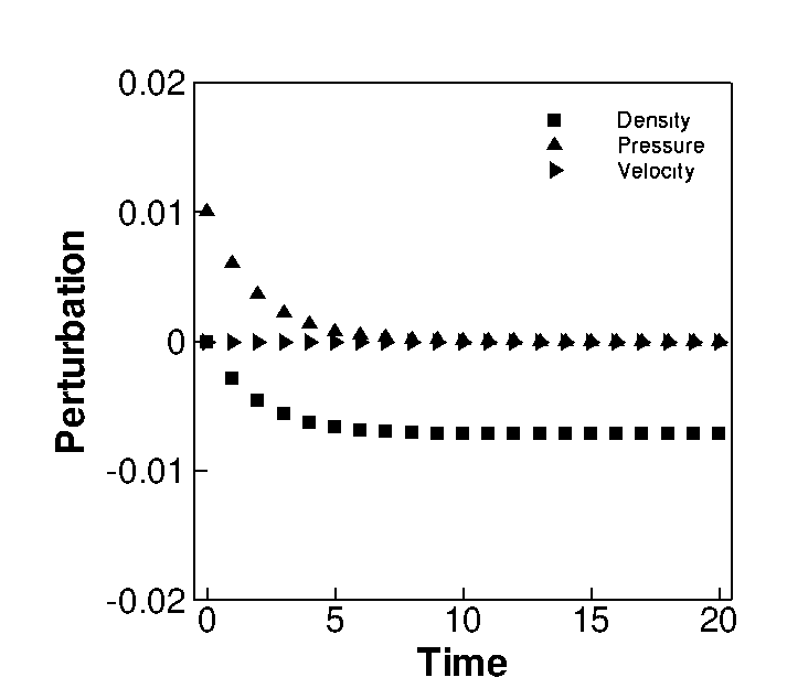
For a in these bounds, it can be seen that any value for will introduce a damping factor of into each of these perturbations. Notice that while this additional factor damps , it provides an ancillary damping to over the preexisting damping coefficient . In case of , the additional damping factor not only ensures that independent perturbations in density are attenuated, but also that any residual perturbations arising in due to action of are also suppressed. Thus in general, the additional factor ensures that the perturbations in all the three primitive quantities die down in time. These behaviours can be clearly observed in Fig.(6). The plots correspond to , and . Given these damping characterisitcs, the HLLEM-SWM class of schemes are very unlikely to produce variation of conserved quantity in the vicinity of the shock profile. This would ensure that numerical solutions of HLLEM-SWM schemes would remain shock instability free.
6.2 Shock stable HLLEM scheme based on antidiffusion control
Since antidiffusion terms in the mass and interface-normal momentum flux discretizations in the transverse direction of the shock front are seen to be instigating the instability, a direct strategy to achieve shock stability in the HLLEM scheme would be to simply reduce the quantity of this term on these crucial transverse interfaces. This can be readily achieved by employing a shock sensor to switch off the antidiffusive terms near a shock. We can define a modified HLLEM scheme, hereby termed as HLLEM-ADC (where ADC stands for Anti Diffusion Control), to be applied on mass and interface-normal momentum flux discretizations on these critical interfaces in the vicinity of a shock wave as,
| (102) |
Our experience shows that unlike the cure discussed in Section.(6.1) which had to be applied on all the interfaces in the vicinity of the numerical shock to be effective, the cure suggested in this section need to be applied only on the interfaces that are transverse to the shock. This may be because we are directly targeting the major trigger for the instability by controlling the antidiffusive terms in these critical flux components. Hence propensity to develop an unphysical variation in conserved quantity along the shock front itself is reduced drastically. To ensure that the antidiffusive terms are withdrawn automatically only on these interfaces, we redefine the shock sensor as,
| (103) |
Note that in the above formulation, the antidiffusion terms concerning both contact and shear waves are treated. However this is not the only possibility. Xie et al [18] have argued that within the antidiffusion term of the HLLEM scheme, it is the one concerning the shear wave resolution represented by that plays the major role in causing the onset of instability. Xie et al [18] use defined in Eq.(99) with chosen to be 3.0 to control only the shear terms in all equations and on all interfaces in the vicinity of the shock. The resulting scheme is called HLLEMS by them.
The perturbation evolution equations for HLLEM-ADC scheme is given in Table(1). The evolution equations of HLLE-ADC in and turns out to be those of the HLLE scheme with the additional antidissipation terms acted upon by the shock sensor . The evolution of resembles that of the HLLE and the HLLEM scheme. The amplification factors for the perturbations are respectively . From these, a strict von-Neumann like stablility criterion on can be derived as,
| (104) |
Thus for and an appropriate choice of under the above constraint, the perturbations and are acted upon by additional damping terms controlled by . The perturbation in itself is damped independent of the action of . However, the rate of feeding into is minimized by leaving no scope for residual to develop as a result of undamped in the flow field. When is equal to 0, we recover the HLLE behaviour with the antidiffusive behaviour completely suppressed.
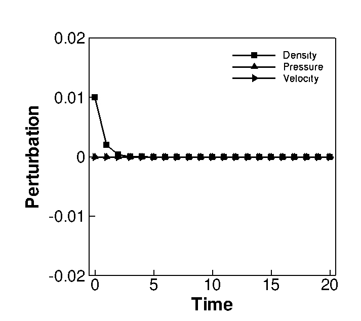
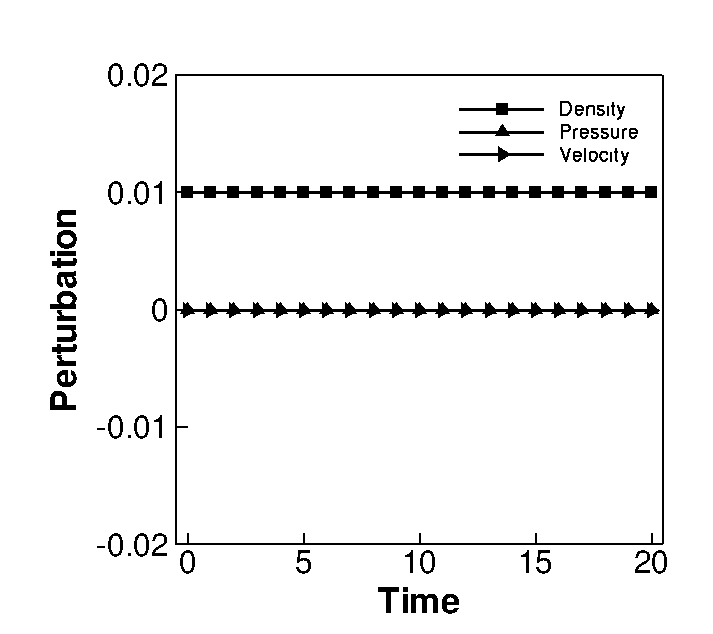
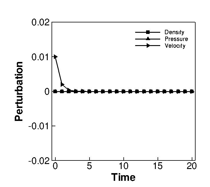
We also present the evolution equations of HLLEMS scheme in Table 1 which was not derived in [18]. The corresponding amplification factors for the perturbations are respectively . It is seen that in comparision to HLLEM-ADC scheme, the HLLEMS scheme allows the action of only on perturbation and not on . The difference between HLLEM-ADC and HLLEMS can be clearly seen from the behavior of . While HLLEM-ADC scheme is able to employ to damp the perturbation , HLLEMS does not have such provisions. Hence any in the solution that is generated will persist in time. Further, although is damped similar to HLLEM-ADC scheme, its effect on is not suppressed. Thus in overall, density perturbations, those that are generated independently and those induced by the feeding of , both remain undamped in case of the HLLEMS scheme. The difference in the evolution equations of these schemes can be more clearly noticed in Fig.(8). As reported in [20] the inability to damp density perturbations could then theoretically cause variations in conserved quantity near shocks and eventually lead to instability. The difference between the quality of solutions produced by these schemes will become evident in certain numerical examples shown later in Section.(7).
7 Numerical results
In this section, we demonstrate the efficacy of the proposed HLLC-SWM and HLLC-ADC schemes through a series of strict shock instability test problems on which many contact-shear preserving Riemann solvers fail. Along with the original HLLEM scheme, solutions for HLLEMS scheme[18] are also provided for comparison in all cases. It has been reported in [23] that the intensity of instability manifestation in certain test problems reduces as the order of accuracy of the computation increases; although it does not completely remove it. Based on this, certain test cases are computed as plain first order while second order solutions are sought for others. Second order spatial accuracy is achieved by limiting gradients of primitive variables obtained using Green Gauss method [26] with Barth Jersperson limiter [27]. Second order time accuracy is achieved using strong stability preserving variant of Runge Kutta method [28]. All boundary conditions are set using ghost cells.
7.1 Moving shock instability problem
Shock instability that occurs in a moving shock propagating down a computational tube was first reported by Quirk [8]. In the present case the strength of the shock is chosen to be M=6 and the computational domain consists of 800 by 20 cells in x and y directions respectively. The shock is made to propagate into a stationary fluid with physical state . The instability is triggered by perturbing the centerline grid of the computational domain to an order of 1E-6. First order solution is sought. The CFL for the computations were taken to be 0.5 and simulations were run till shock reached a location x=650. The results showing fifty density contours equally spanning values from 1.4 to 7.34 is shown in Fig.(9).


Fig.(9a) clearly shows the deteriorated condition of the shock profile calculated by the HLLEM scheme. Fig.(9b) and Fig.(9c) demonstrates that both versions of HLLC-SWM scheme are free from instability on this problem. Fig.(9d) and Fig.(9e) show that both full and partial control of antidissipation removes instability on this problem.
7.2 Double Mach Reflection problem
To demonstrate the robustness of the proposed schemes, another standard test problem called Double Mach reflection problem is used [29]. For the present test, a domain of is chosen and is constituted of structured Cartesian cells. An oblique shock corresponding to , making a angle with the bottom wall at is made to propagate through the domain. Cells ahead of the shock are initialized with values while those after the shock are set to appropriate post shock conditions. Inlet boundary is maintained at post shock conditions while zero gradient condition is used at outlet boundary. Top boundary conditions are adjusted to allow for propagation of shock front. At the bottom, post shock conditions are maintained till after which invisid wall conditions are used. The simulation is run till with CFL of 0.8. The problem is computed to first order accuracy. Fig.(10) shows results of the experiment with twenty five density contours equally spanning values from 1.4 to 21.
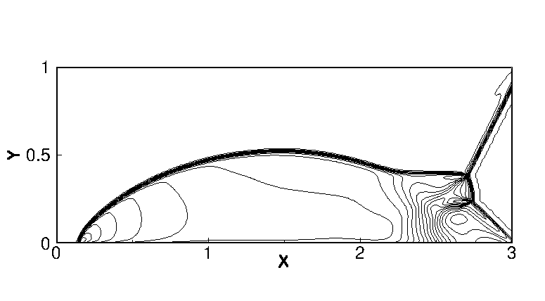
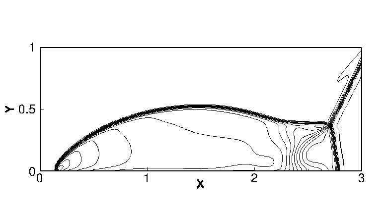
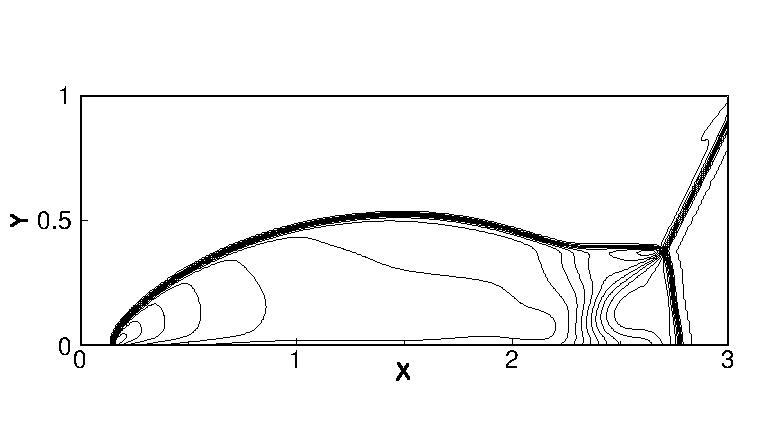
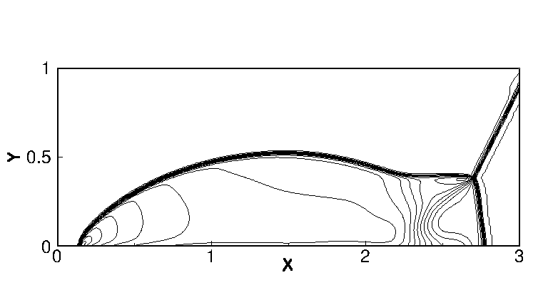
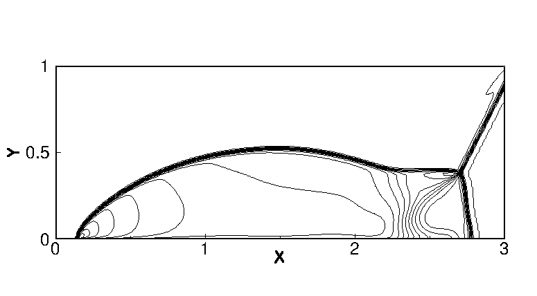
Fig.(10a) clearly shows the presence of kinked Mach stem and the subsequent triple point produced by HLLEM scheme. The solutions computed by HLLEM-SWM schemes, HLLC-ADC and HLLEMS show no trace of instability.
7.3 Hypersonic flow over a blunt body
Another routine test problem that is used to investigate the susceptibility of a numerical scheme to shock instability is the steady state numerical solution of a supersonic or hypersonic flow over cylindrical body. The instability in this problem manifests as distorted contour lines and in certain extreme cases, complete obliteration of the shock profile. The unstable soluton will result in erroneous stagnation values of physical quantities which may eventually affect heat transfer predictions [30]. The problem is set up by placing a cylindrical body of radius 1 unit in a M=20 flow with free stream conditions given as . The computational mesh is prepared using method described in [31] wherein 32040 body fitted structured quadrilateral cells are used in circumferential and radial directions respectively. To instigate the instabilities, we perturb the radial grid line that lies along y=0 in a saw-tooth profile at the order of 1E-4. The inlet boundary is maintained as supersonic inlet while at the solid wall, impermeability is prescribed with density and pressure are extrapolated from the internal cell. Simple extrapolation is employed at top and bottom boundaries. The computation of this problem is carried out to first order accuracy. The CFL for the computations were taken to be 0.5 and simulations were run for 20,000 iterations. The results showing twenty density contours equally spanning value from 1.4 to 8.5 is shown in Fig.(11).


Fig.(11a) clearly shows the occurrence of the Carbuncle phenomenon in the solution computed by the HLLEM scheme. Amongst all the schemes, solution obtained using the HLLC-SWM-E given in Fig.(11c) seems to be the most smoothest. HLLC-SWM-P also produces quite comparable solution to the HLLC-SWM-E scheme. On the other hand, the difference between full and partial antidiffusion control strategies used by the HLLC-ADC and the HLLEMS schemes respectively is evident on this test case. While the solution computed by HLLC-ADC in Fig.(11d) shows no signs of perturbations, the one computed by HLLEMS in Fig.(11e) shows clear asymmetry near the centerline. This could indicate that switching off antidiffusion terms corresponding to the shear waves alone may not be sufficient for complete removal of instability.
7.4 Diffraction of a moving normal shock over a 900 corner
The problem of a Mach 5.09 normal shock’s sudden expansion around a corner was studied in [8]. A unit dimensional domain is meshed with 400 400 cells. The right angled corner is located at . To begin with, the normal shock is located at . Remaining cells are initialized to a stationary fluid with properties and . The inlet boundary is maintained as post shock conditions while outlet boundary is set to zero gradient. Top boundary is adjusted to allow shock propagation. Bottom boundary behind the corner uses extrapolated values from within the domain. The corner surface is maintained as reflective wall. The problem is computed to second order accuracy. Simulations are run for units with CFL of 0.4. Thirty density contours equally spanning values of 0 to 7 are shown in Fig.(12).


Fig.(12a) clearly demonstrates the extent of instability present in the computed shock profile produced by HLLEM scheme. A part of the normal shock in the right corner is completely distorted in this case. Although solutions have quite improved, some benign amount of perturbation is observed close to the top boundary in solutions computed by HLLC-SWM schemes and HLLEMS scheme as seen in Figs.(12b,12c and 12e). The solution computed by HLLC-ADC seems to be the most cleanest among all the schemes.
7.5 Supersonic flow over forward facing step
Supersonic flow over forward facing step is another standard problem that has been extensively studied earlier in [29]. The computational domain is of size . A 0.2 units high step is located at a distance of 0.6 units from the inlet. The domain is meshed with structured Cartesian cells. An initial value of that corresponds to a M=3 supersonic flow is provided in the whole domain. The inlet boundary is maintained as freestream while the outlet boundary is set to zero gradient. The top and the bottom walls are set as inviscid walls. The problem is computed to second order accuracy. The simulations are run for t=4 with CFL as 0.5. Fig.(13) shows forty equispaced density contours spanning 0.2 to 7.0.


It is seen from Fig.(13a) that predominant perturbations are visible in the shock profile computed by HLLEM scheme. These are most prominent at the normal shock stems of the primary shock near the bottom and top boundaries. Further, HLLEM solution also has a severely distorted stem in the reflected shock. The solutions by HLLEM-SWM, HLLEM-ADC and HLLEMS shows marked improvement compared to that of HLLEM. In all the cases the perturbations in shock profile is non existent and the reflected shock stem is captured well near the solid wall.
7.6 Inclined stationary shock instability problem
This problem was reported in [32]. In the present setup a stationary shock is initialized at an angle of with respect to the global x-direction. The computation mesh consists of 5030 cells uniformly spanning a domain of size 50.030.0. The initial shock wave is set up along the line y=2(x-12). The conditions before the shock wave are provided using the conditions and it describes a supersonic flow normal to the shock front. The after shock conditions are given as . The left and right boundaries are maintained as supersonic inlet and subsonic outlet respectively. At the top boundary cells from 1 to 15 are maintained as supersonic inlet while all the remaining cells are set periodic to the corresponding bottom internal cells. At the bottom, cells from 36 to 50 are set as subsonic outlet while the remaining cells are set periodic to the corresponding cells at the top internal cells. CFL of the computation was chosen as 0.5 and first order solution was sought at t=5. Fig.(15) shows the result of this experiment where thirty density contours uniformly spanning 1.0 to 5.44 are shown.


Fig.(14a) shows the presence of instability in the HLLEM scheme. Fig.(15a) shows the density variation along the shock front extracted just behind the shock. The density variation has a typical saw tooth profile that is characteristic of a shock unstable solution. Figs.(14b,14c) show that both the HLLEM-SWM variants are able to fix this issue providing a clean shock profile. The respective density variations in Fig.(15b,15c) confirm this observation. It is interesting to see from Figs.(14d,14e) that amongst the HLLEM fixes that aims to control the antidiffusion terms to achieve shock stability, only the HLLEM-ADC variant is able to completely save the HLLEM scheme from instability. The density variation behind shock shown in Fig.(15e) corresponding to the HLLEMS scheme indicates that controlling only the shear component may not suffice in curing instability. Hence, for a complete removal of instability in case of HLLEM scheme, total control of the antidissipation vector has to be achieved as observed from the analysis is Section.(5).
7.7 Laminar flow over flat plate (Viscous)
Since all the cures discussed in Sec.(6) are based on introducing some or the other form of dissipation into HLLEM scheme, it is imperative to check how these extraneous dissipation affects resolution of shear layers. To this end, the classic test case of a laminar flow over a flat plate is used. The problem is set up as follows: A flow with , pressure of 41368.5 Pa, temperature of 388.88 K, constant dynamic viscosity of 2.23 , gas constant of 287.0 , coefficient of specific heat at constant pressure Cp of 1005.0 and Prandlt number of 0.72 is computed over a flat plate of length L=0.3048 m. The total length of the domain is 0.381 m in x direction and 0.1 m in y direction. The domain is divided into 3133 Cartesian cells. While uniform meshing is done in the x direction, a non-uniform grid spacing is preferred in the y direction with atleast 15 cells within the boundary layer. Viscous fluxes were discretized using the Coirier diamond path method discussed in [33, 34]. CFL was taken to be 0.7. The flow was considered to have achieved steady state when the horizontal velocity residuals dropped to the order of . The normalized longitudinal velocity profiles are plotted against the Blasius parameter in Fig.(16).
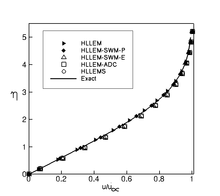
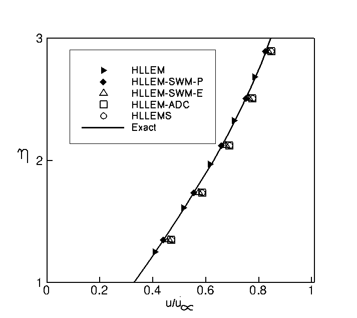
It is clearly seen from Fig.(16a) that the HLLEM-SWM-P is able to exactly resolve the boundary layer as well as the HLLEM scheme. The HLLEM-SWM-E scheme is also quite accurate although it is incapable of exact resolution. The HLLEM-ADC and the HLLEMS schemes are both dissipative compared to these HLLEM-SWM class of schemes. This is quite evident in Fig.(16b) where a zoomed-in plot is shown with . It can be inferred that slightly away from the wall, the pressure sensor employed in these schemes are active on the transverse interfaces due to variations in pressure along the plate leading to unwanted reduction in quantity of antidiffuisve terms. However close to the wall, all cures are found to be capable of satisfactorily resolving the velocity gradient.
8 Conclusions
In this paper we presented some strategies to construct various versions of shock stable HLLEM scheme. We began by analyzing the numerical dissipation characteristics of the HLLE and the HLLEM schemes in the vicinity of a normal shock using a linear scale analysis technique. It was observed that in the transverse direction of a normal shock subjected to numerical perturbations, the antidiffusive terms in the mass and interface-normal momentum flux discretizations of the HLLEM scheme gets activated which in turn causes a weakening of its inherent HLL-type dissipation. The overall reduced dissipation of the HLLEM scheme is found to be incapable of attenuating perturbations in and quantities which leads to unphysical variation of conserved quantity along the length of the shock profile and eventually to a shock unstable solution. Based on this understanding, two different strategies were applied in the vicinity of a shock. The first method termed HLLEM-SWM aimed to increase the magnitude of the dissipation of the inherent HLL component in the mass and interface-normal momentum flux discretizations by careful manipulation of certain non-linear wave speed estimates appearing in the HLL-type diffusion vector. The quantity of additional dissipation to be infused was obtained through local solution dependent multidimensional shock sensors based on eigenvalues or on pressure ratios. However this cure is more effective when applied on all interfaces near a shock wave; ie. along and across a shock front. The second method termed HLLEM-ADC, instead, aimed to directly control these critical antidiffusive terms using a pressure based shock sensor and need to be applied only on the interfaces along the shock front. This makes it the cheapest method amongst the cures discussed here. A linear perturbation analysis of these cures revealed the differences in the damping mechanisms they employ to ensure that the perturbations in and quantities are attenuated. A von-Neumann type stability bounds on the CFL number that is applicable for their effectiveness was derived. It was also noticed that the HLLEMS scheme, which treats only the antidiffusive terms corresponding to shear waves, is incapable of damping perturbations in density variable and hence is instability prone. A suite of stringent numerical test cases were used to demonstrate the efficacy and robustness of the methods discussed in this paper. It was found that the proposed schemes perform better than HLLEMS scheme for certain numerical test examples like stability of an inclined stationary shock and hypersonic flow over a bluntbody.
References
- [1] P. Roe, “Approximate Riemann solvers, parameter vectors, and difference schemes,” J. Comput. Phys., vol. 43, pp. 357–372, 1981.
- [2] A. Harten, P. D. Lax, and B. van Leer, “On upstream differencing and Godunov-type schemes for hyperbolic conservation laws,” SIAM Rev., vol. 25, pp. 35–61, 1983.
- [3] B. Einfeldt, “On godunov-type methods for gas dynamics,” SIAM Journal on Numerical Analysis, vol. 25, no. 2, pp. 294–318, 1988.
- [4] E. Toro and V. Cendon, “Flux splitting schemes for the Euler equations,” Comput and Fluids, vol. 70, pp. 1–12, 2012.
- [5] B. van Leer, J. L. Thomas, P. L. Roe, and R. W. Newsome, A comparison of numerical flux formulas for the euler and navier-stokes equations, pp. 36–41. American Institute of Aeronautics and Astronautics Inc, AIAA, 1987.
- [6] B. Einfeldt, C. D. Munz, P. L. Roe, and B. Sjogreen, “On Gudonov type methods near low densities,” J. Comput. Phys., vol. 92, pp. 273–295, 1991.
- [7] K. M. Peery and S. T. Imlay, “Blunt-Body Flow Simulations,” in AIAA Paper 88-2904, 1988.
- [8] J. J. Quirk, “A contribution to the great Riemann solver debate,” Int. J. Numer. Methods Fluids, vol. 18, pp. 555–574, 1994.
- [9] R. Sanders, E. Morano, and M. C. Druguet, “Multidimensional dissipation for upwind schemes:Stability and applications to gas dynamics,” J. Comput. Phys., vol. 145, pp. 511–537, 1998.
- [10] Z. Shen, W. Yan, and G. Yuan, “A stability analysis of Hybrid schemes to cure shock instability,” Commun. Comput. Phys., vol. 15, pp. 1320–1342, 2014.
- [11] Y.-X. Ren, “A robust shock-capturing scheme based on rotated riemann solvers,” Comput and Fluids, vol. 32, pp. 1379 – 1403, 2003.
- [12] H.-C. Lin, “Dissipation additions to flux-difference splitting,” Journal of Computational Physics, vol. 117, no. 1, pp. 20 – 27, 1995.
- [13] M. Pandolfi and D. D’Ambrosio, “Numerical instabilities in upwind methods: Analysis and cures for the “Carbuncle” phenomenon,” J. Comput. Phys., vol. 166, pp. 271–301, 2001.
- [14] S. S. Kim, C. Kim, O. Rho, and S. Hong, “Cures for the shock instability: Development of a shock stable Roe scheme,” J. Comput. Phys, vol. 185, pp. 342–374, 2003.
- [15] F. Ismail, Toward A Reliable Prediction Of Shocks In Hypersonic Flow: Resolving Carbuncles With Entropy And Vorticity Control. PhD thesis, University of Michigan, 2006.
- [16] H. Nishikawa and K. Kitamura, “Very simple carbuncle free boundary layer resolving rotated hybrid riemann solvers,” J. Comput. Phys, vol. 227, pp. 2560–2581, 2008.
- [17] S. H. Park and J. H. Kwon, “On the dissipation mechanism of Godunov-type schemes,” vol. 188, 2003.
- [18] W. Xie, W. Li, H. Li, Z. Tian, and S. Pan, “On numerical instabilities of Godunov-type schemes for strong shocks,” Journal of Computational Physics, vol. 350, pp. 607–637, 2017.
- [19] S. Obayashi and Y. Wada, “Practical formulation of a positively conservative scheme,” AIAA journal, vol. 32, no. 5, pp. 1093–1095, 1994.
- [20] S. Simon and J. C. Mandal, “A cure for numerical shock instability in hllc riemann solver using antidiffusion control,” 2018. arXiv:1803.04954.
- [21] S. Simon and J. C. Mandal, “A simple cure for numerical shock instability in hllc riemann solver,” 2018. arXiv:1803.04922.
- [22] J. Mandal and V. Panwar, “Robust hll-type riemann solver capable of resolving contact discontinuity,” Comput and Fluids, vol. 63, pp. 148 – 164, 2012.
- [23] J. Gressiera and J.-M. Moschetta, “Robustness versus accuracy in shock-wave computations,” Int. J. Numer. Methods Fluids, vol. 33, pp. 313–332, 2000.
- [24] E. Toro, Riemann Solvers and Numerical Methods for Fluid Dynamics: A Practical Introduction. Springer Berlin Heidelberg, 2009.
- [25] F. Zhang, J. Liu, B. Chen, and W. Zhong, “A robust low-dissipation ausm-family scheme for numerical shock stability on unstructured grids,” Int. J. Numer. Methods Fluids, vol. 84, pp. 135–151, 2017.
- [26] J. Blazek, Computational Fluid Dynamics: Principles and Applications (Second Edition). Elsevier Science, 2005.
- [27] T. Barth and D. Jesperson, The design and application of upwind schemes on unstructured meshes. American Institute of Aeronautics and Astronautics Inc, AIAA, 1989.
- [28] S. Gottlieb, C.-W. Shu, and E. Tadmor, “Strong Stability-Preserving High-Order Time Discretization,” SIAM Rev., vol. 43, no. 1, pp. 89–112, 2001.
- [29] P. Woodward and P. Colella, “The numerical simulation of two-dimensional fluid flow with strong shocks,” J. Comput. Phys, vol. 54, no. 1, pp. 115 – 173, 1984.
- [30] K. Kitamura, E. Shima, Y. Nakamura, and P. L. Roe, “Evaluation of Euler Fluxes for Hypersonic Heating Computations,” AIAA Journal, vol. 48, no. 4, pp. 763–776, 2010.
- [31] K. Huang, H. Wu, H. Yu, and D. Yan, “Cures for numerical shock instability in hllc solver,” Int. J. Numer. Methods Fluids, vol. 65, pp. 1026–1038, 2011.
- [32] T. Ohwada, R. Adachi, K. Xu, and J. Luo, “On the remedy against shock anomalies in kinetic schemes,” Journal of Computational Physics, vol. 255, pp. 106–129, 2013.
- [33] W. Coirier, An adaptively refined Cartesian, cell based scheme for the Euler and Navier-Stokes equations. PhD thesis, University of Michigan, 1994.
- [34] J. C. Mandal and S. P. Rao, “High resolution finite volume computations on unstructured grids using solution dependent weighted least squares gradients,” Computers and Fluids, vol. 44, no. 1, pp. 23–31, 2011.