Operating a near-concentric cavity at the last stable resonance
Abstract
Near-concentric optical cavities of spherical mirrors can provide technical advantages over the conventional near-planar cavities in applications requiring strong atom-light interaction, as they concentrate light in a very small region of space. However, such cavities barely support stable optical modes, and thus impose practical challenges. Here, we present an experiment where we maintain a near-concentric cavity at its last resonant length for laser light at 780 nm resonant with an atomic transition. At this point, the spacing of two spherical mirror surfaces is nm shorter than the critical concentric point, corresponding to a stability parameter and a cavity beam waist of m.
pacs:
32.90.+a, 37.30.+i, 42.50.CtI Introduction
Optical cavities are widely used, ranging from lasers and gravitational wave detectors to experiments in quantum physics exploring nonlinear atom-light interaction. In particular, atom-cavity systems with ultra-high finesse cavities are a key component in demonstrations of quantum logic gates, distributed quantum networks, quantum metrology, and sensing applications (Reiserer and Rempe, 2015; Ritter et al., 2012; Reiserer et al., 2014) using cavity quantum electrodynamics. The intricate high-reflectivity coatings of the cavity mirrors used in these experiments, however, can pose a challenge on scaling systems up. Therefore, new types of optical cavities and resonance structures to enhance the electrical field of an optical mode have been considered recently (Cox et al., 2018; Nguyen et al., 2017). One such a cavity design that has been experimentally demonstrated is a near-concentric Fabry-Perot cavity (Morin et al., 1994; Nguyen et al., 2017). Outside the field of cavity QED, these near-unstable cavities have been considered to reduce the influence of thermal noise of the mirror coatings on gravitational wave detectors (Wang et al., 2018).
Near-concentric cavities are formed by two spherical mirrors with a normal separation just short of the sum of the two radii of curvatures. Among all geometries of Fabry-Perot cavities, near-concentric cavitiesexhibit the tightest focus of the cavity modes. A tight focus leads to a large electrical field in the focus, and therefore a strong coupling to an atom trapped there.
In a near-concentric cavity with a length of several millimeters, the effective mode volume can be very small and comparable to state-of-the-art cavities of micrometer lengths. The relatively large mirror separation permits to form a cavity with a narrow spectral linewidth already with mirrors of low finesse that are less challenging to make. Other advantages are a better optical access to the focal region, which can be helpful for preparation and manipulation of quantum emitters like atoms or ions.
Furthermore, the near-degeneracy in resonant frequencies of transverse modes of near-concentric cavities is an intriguing feature to explore the physics of multi-mode strong coupling in cavity quantum electrodynamics (Ballantine et al., 2017).
However, near-concentric cavities have not been widely explored yet, mainly because they require mirrors that cover a relatively large solid angle, and because of technical hurdles of stabilizing both the longitudinal and transverse mirror positions.
Here, we report on a compact design of a symmetric near-concentric cavity with a length of 11 mm corresponding to a free spectral range of 13.6 GHz, and the strategy to stabilize it to the last few stable resonances near the concentric point. The design is intended to study atom-light interaction but can be easily adapted to a wider range of experiments.
II Optical setup
II.1 Cavity design
The spherical cavity mirrors of our cavity have a radius of curvature mm, and a nominal reflectivity of at a wavelength of 780 nm. For effective matching to an external probe mode, we use an ellipsoidal second surface to transform a collimated (Gaussian) input mode into a spherical wave at the mirror surface. The details of characterization and abberations analysis of the mirrors can be found in (Durak et al., 2014).
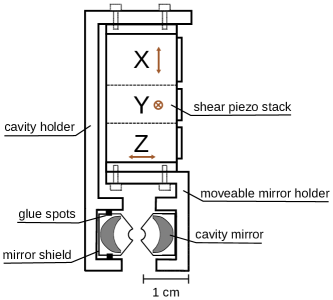
To align the cavity and correct for thermal drifts, we place one of the cavity mirrors on a shear piezo stack with a travel range of m in three orthogonal directions. The cavity mounting system is shown in Fig. 1 and fits into a cuvette of a vacuum chamber which provides convenient optical access to the cavity focus for other optical beams preparing atoms in experiment.Except for the cavity mirror shields, all the mechanical parts are made from Titanium to reduce the structural change of the mounting system due to thermal fluctuation.
II.2 Alignment procedure
The relatively large numerical aperture of near-concentric cavity modes and the aspheric outside surface of the cavity mirrors require that the optical axes of the two cavity mirrors coincide – a requirement that is much less critical in conventional cavity arrangements. Additionally, the absolute transverse separation of the mirror surfaces needs to be near the critical distance within the moving range of the piezo translator.
A collimated laser beam between two fiber couplers defines a reference line for the alignment of the cavity mirrors. One cavity mirror is pre-assembled in the movable mirror holder. Then the other cavity mirror is gradually moved into the cavity holder on an external translation stage. Throughout the alignment process, the reflected beams from the two cavity mirrors are monitored and ensured to couple back to the optical fibers. This keeps the tilt of the mirrors under control, and provides a coarse transverse alignment between the two cavity mirrors. The fine adjustment is carried out by a piezo system on the external translation stage, before the mirror is glued into the aligned position inside the cavity holder.
II.3 Longitudinal locking scheme
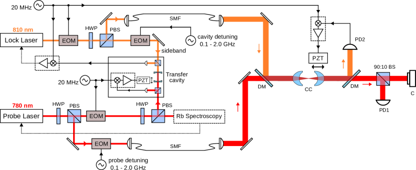
As we intend to use the cavity for cavity QED experiments, we need to stabilize its resonance frequency with respect to an atomic transition independently from the light used to interact with the atom-cavity system. Therefore, a separate wavelength, far detuned from the atomic transition under consideration is used. The optical layout of the locking scheme is shown in Fig. 2. Laser light at wavelengths of 780 nm and 810 nm is coupled into the near-concentric cavity, which we refer to as probe and the lock light, respectively. The probe laser is referenced to a D2 transition of 87Rb via a modulation transfer spectroscopy McCarron et al. (2008). The stability of the probe laser is passed to the lock laser at 810 nm wavelength via a transfer cavity. For that, the transfer cavity is first locked to the probe laser. Then, one sideband generated by an electro-optical-modulator (EOM) on the 810 nm light is locked to a resonance of the transfer cavity. By tuning the frequency of the sideband, the frequency of the lock laser can be adjusted, and is chosen such that the probe and lock beams are simultaneously resonant with the near-concentric cavity. The probe light itself can be tuned around the atomic resonance through another EOM in a similar way. All locks use the standard Pound-Drever-Hall technique (Drever et al., 1983) with additional sidebands at 20 MHz which never reach the near-concentric cavity.
III Cavity length measurement
The eigenmodes of an optical resonator with spherical mirrors can be described by Laguerre-Gaussian (LG) functions, as they form a complete basis to solutions of the paraxial wave equation, and capture well the cylindrical symmetry of the resonator along the optical axis Allen et al. (1992). We denote cavity modes as with integer number mode indices . Modes of different identify longitudinal modes, while and characterize the transverse mode profile. The resonance frequencies of the cavity modes are fixed by the condition that the round-trip phase shift in the cavity must be an integer multiple of . As the cavity length approaches concentric point, the shift of the transverse mode frequencies approaches the free spectral range. Therefore all transverse modes become co-resonant in the concentric regime.
Making use of this property, we determine the cavity length by measuring the spacing of resonant frequencies between the fundamental mode and the transverse mode . Under paraxial approximation, the resonance frequencies of the cavity with identical spherical mirrors are given by
| (1) |
where is the speed of light, the Gouy phase difference after one round trip of , and the Rayleigh range of the cavity (Saleh and Teich, 2001).

From Eq. (1) follows an expression for frequency spacing of and in terms of and ,
| (2) |
where is the stability parameter.
In the experiment, we obtain cavity transmission spectra by varying the cavity length within a free spectral range. We record spectra at different resonant cavity lengths, and apply a peak detection algorithm to determine the resonant frequencies. Different transverse modes are disinguished by imaging the intensity distribution of light transmitted through the cavity with a camers. The frequency measurements are calibrated with a frequency marker obtained by modulating the probe laser with an electro-optical phase modulator (EOM).
Figure 3 shows the transverse mode frequency spacing at different cavity lengths which are resonant with the 780 nm laser. We define the critical distance as . From a fit of experimental data points to Eq. 2, we determine nm at the last stable resonance, which corresponds to the stability parameter . This is consistent with our observation that when increasing the cavity length by another half wavelength, the cavity enters the unstable regime and exhibits lossy cavity modes (see Fig. 4 and the next section).
The good agreement between the experimental data, including the last resonant point, and the fit based on the paraxial equation prompts us to discuss the validity of the paraxial approximation in our near-concentric cavity. In the paraxial approximation, the complex electric field amplitude of a beam propagating in the direction can described as , where is the longitudinal wave vector component, and an envelope function; its slow variation in the paraxial approximation requires
| (3) |
Conventionally, Eq. 3 is considered valid for optical beam components with an angle with the optical axis up to 30 degrees Siegman (1986). Transverse fundamental near-concentric cavity modes (LGn00) have a beam divergence of , where is the wavelength of the resonant mode (780 nm in our case) and is the cavity beam waist. Taking the beam divergence now as a characteristic angle with the optical axis, the divergence limit of 30 degrees for the paraxial approximation corresponds to nm, or equivalently nm. The region of critical distances we explore is much larger, so the paraxial approximation is still valid. Note that the definition of the critical distance and validity of Eq. (1) are based on a meaningful definition of a mirror surface position. The thickness of the dielectric Bragg stacks forming the mirrors for our cavity exceeds by far the critical distances for the last stable longitudinal resonances, so the absolute position of the mirror surface has to refer to an effective position of these Bragg stacks.
IV Cavity mode analysis
Earlier observations indicated that the cavity finesse reduces significantly as the cavity is pushed toward the geometrical instability regime Haase et al. (2006). In contrast to this, possibly due to refined manufacturing techniques of large angle spherical mirror surfaces, we find that our near-concentric cavity can maintain the transmission and linewidth at the last two resonant cavity lengths before the unstable regime. Typical cavity transmission spectra are shown in Fig. 4. To characterize line widths of sligthly overlapping cavity modes, we model the cavity transmission by a sum of two Lorentzian functions,
| (4) |
where are transmission coefficients, resonant frequencies, and the line widths of cavity modes and . From a fit of Eq. (4) to cavity transmission spectra we then determine the cavity parameters at multiple cavity lengths.

We find that at nm, the last longitudinal resonance of the cavity, fundamental mode maintains the cavity linewidth and transmissions of other longitudinal resonances. The observed linewidth of the fundamental mode still agrees well with the nominal value of 21.7 MHz determined from the cavity mirror’s design reflectivity of 0.995 at a wavelength of 780 nm. In contrast, the transverse modes start to overlap at the last resonant length, and the probe laser simultaneously couples to multiple cavity modes such that the second cavity mode becomes difficult toidentify, resulting in a broadened effective linewidth of 98(2) MHz from the fit. An increase of the cavity length by another half wavelength leads to a decrease in the cavity transmission and, an increase in the cavity linewidth, which are indicative of unstable cavity modes.
Besides the scattering and absorption loss, due to the finite mirror aperture, the cavity can exhibit additional geometrical diffraction losses if there is misalignment between the two optical axes of the cavity mirrors. This loss becomes more critical for near-unstable cavities. Hence, we try to assess the misalignment in our cavity based on the observed variation of cavity linewidth across the cavity lengths. Under the assumption that the misalignment is entirely due to the tilting of the mirrors, the diffraction loss per round trip is given by (Hauck et al., 1980):
| (5) |
where is the misalignment angle, the radius of cavity mirror aperture, and the beam waist on the mirrors. Attributing all cavity losses to such diffraction losses bounds the misalignment to about 0.5 degrees. This is compatible with what we expect from the alignment procedure, as the reflected laser beams from the cavity mirrors are ensured to couple back to the optical fibers.

V Transverse stabilization
The alignment of near-concentric cavities is sensitive to the transverse positions of the cavity mirrors. To quantify this, we measure the coupling efficiency of a resonant cavity mode to the mode defined by a single mode fiber as we displace one of the cavity mirrors in x and y directions (see Fig. 5). Throughout the measurement, the cavity length is locked to the frequency stabilized 810 nm laser. The transmission profiles in Fig. 5 show a FWHM of 42(8) nm and 54(10) nm for displacements in x and y. We observe a drift of 22 nm of cavity alignment over a time of one hour. With the thermal expansion coefficients of the cavity setup, such a change of the fundamental mode transmission by 10% could be caused by a temperature change on the order of 100 mK. Practical operation of a near-concentric cavity therefore requires either careful temperature stabilization of the setup, or a transverse locking scheme.

To actively compensate for transverse drifts, we implement a two-dimensional lock-in algorithm based on gradient search method to maximize the cavity transmission for the two transverse displacement variables. Figure 6 shows a typical record of cavity transmission at the last resonant length when the stabilization algorithm is activated at two instances. The slow drift on the order of minutes between these instances is probably caused by the temperature change of the cavity. The average search time to recover the maximum cavity transmission is on the order of seconds, and thus would not significantly reduce the duty cycle of an experiment. With both temperature stabilization and active transverse stabilization, the near-concentric cavity remains aligned for a few hours.
VI Conclusion
We presented a compact design, alignment procedure and stabilization methods of a Fabry-Perot near-concentric optical cavity. In our experiment, we find that the cavity design preserves cavity linewidth and cavity transmission when being operated at 207(13) nm shorter than the concentric point, the last longitudinal resonance for this cavity setup.
At this cavity length, the measured transverse mode frequency spacing of 40(5) MHz is of the same order as the estimated atom-cavity coupling strength of 20 MHz for a Rb atom placed into the cavity mode. This permits to probe the dynamics of an atomic state when strongly coupling to several cavity modes, opening an avenue to experimentally explore multi-mode cavity QED in the optical regime, and new schemes of interaction of photons simultaneously present in different modes.
Acknowledgements.
This work was supported by the Ministry of Education in Singapore and the National Research Foundation, Prime Minister’s office (partly under grant no NRF-CRP12-2013-03).References
- Reiserer and Rempe (2015) A. Reiserer and G. Rempe, Reviews of Modern Physics 87, 1379 (2015), arXiv:1412.2889 .
- Ritter et al. (2012) S. Ritter, C. Nölleke, C. Hahn, A. Reiserer, A. Neuzner, M. Uphoff, M. Mücke, E. Figueroa, J. Bochmann, and G. Rempe, Nature 484, 195 (2012), arXiv:1202.5955 .
- Reiserer et al. (2014) A. Reiserer, N. Kalb, G. Rempe, and S. Ritter, Nature 508, 237 (2014), arXiv:1404.2453 .
- Cox et al. (2018) K. C. Cox, D. H. Meyer, N. A. Schine, F. K. Fatemi, and P. D. Kunz, (2018), arXiv:1802.05707 .
- Nguyen et al. (2017) C. H. Nguyen, A. N. Utama, N. Lewty, K. Durak, G. Maslennikov, S. Straupe, M. Steiner, and C. Kurtsiefer, Physical Review A 96, 031802 (2017), arXiv:1706.01256 .
- Morin et al. (1994) S. E. Morin, C. C. Yu, and T. W. Mossberg, Physical Review Letters 73, 1489 (1994).
- Wang et al. (2018) H. Wang, M. Dovale-Álvarez, C. Collins, D. D. Brown, M. Wang, C. M. Mow-Lowry, S. Han, and A. Freise, Physical Review D 97, 022001 (2018), arXiv:1711.05177 .
- Ballantine et al. (2017) K. E. Ballantine, B. L. Lev, and J. Keeling, Physical Review Letters 118, 045302 (2017), arXiv:1608.07246 .
- Durak et al. (2014) K. Durak, C. H. Nguyen, V. Leong, S. Straupe, and C. Kurtsiefer, New Journal of Physics 16, 103002 (2014), arXiv:1404.7672 .
- McCarron et al. (2008) D. J. McCarron, S. A. King, and S. L. Cornish, Measurement Science and Technology 19, 105601 (2008), arXiv:0805.2708 .
- Drever et al. (1983) R. W. P. Drever, J. L. Hall, F. V. Kowalski, J. Hough, G. M. Ford, A. J. Munley, and H. Ward, Applied Physics B Photophysics and Laser Chemistry 31, 97 (1983), arXiv:1602.03504 .
- Allen et al. (1992) L. Allen, M. W. Beijersbergen, R. J. C. Spreeuw, and J. P. Woerdman, Physical Review A 45, 8185 (1992).
- Saleh and Teich (2001) B. E. A. Saleh and M. C. Teich, “Resonator Optics,” in Fundamentals of Photonics (John Wiley & Sons, Inc., 2001) pp. 310–341.
- Siegman (1986) A. E. Siegman, Lasers (University Science Books, 1986).
- Haase et al. (2006) A. Haase, B. Hessmo, and J. Schmiedmayer, Optics Letters 31, 268 (2006), arXiv:0510166 [physics] .
- Hauck et al. (1980) R. Hauck, H. P. Kortz, and H. Weber, Applied Optics 19, 598 (1980).