Electronic Properties of Substitutionally Boron-doped Graphene Nanoribbons
on a Au(111) Surface
Abstract
High quality graphene nanoribbons (GNRs) grown by on-surface synthesis strategies with atomic precision can be controllably doped by inserting heteroatoms or chemical groups in the molecular precursors. Here, we study the electronic structure of armchair GNRs substitutionally doped with di-boron moieties at the center, through a combination of scanning tunneling spectroscopy, angle-resolved photoemission, and density functional theory simulations. Boron atoms appear with a small displacement towards the surface signaling their stronger interaction with the metal. We find two boron-rich flat bands emerging as impurity states inside the GNR band gap, one of them particularly broadened after its hybridization with the gold surface states. In addition, the boron atoms shift the conduction and valence bands of the pristine GNR away from the gap edge, and leave unaffected the bands above and below, which become the new frontier bands and have negligible boron character. This is due to the selective mixing of boron states with GNR bands according to their symmetry. Our results depict that the GNRs band structure can be tuned by modifying the separation between di-boron moieties.
Ikerbasque, Basque Foundation for Science, 48013 Bilbao, Spain \alsoaffiliationDonostia International Physics Center, 20018 Donostia-San Sebastián, Spain \alsoaffiliationDpto. Física de la Materia Condensada, Univ. de Zaragoza, E-50009 Zaragoza, Spain \alsoaffiliationDonostia International Physics Center, 20018 Donostia-San Sebastián, Spain \alsoaffiliationIkerbasque, Basque Foundation for Science, 48013 Bilbao, Spain \alsoaffiliationIkerbasque, Basque Foundation for Science, 48013 Bilbao, Spain
1 Introduction
Graphene nanoribbons (GNRs) have emerged as a low dimensional platform for nanoelectronics with promising applications due to the predictive control on their functionality 1. Most GNRs are predicted to be one-dimensional semiconductors, with a band-gap that depends on their width and orientation 2, 3. However, due to their low dimensions, their electronic properties are extremely sensitive to atomic-scale defects and inhomogeneities appearing during their fabrication. On-surface chemistry strategies allow producing atomically precise nanoribbons with perfectly well-defined widths and edges, using organic precursors and directing their reaction over a metal surface 4, 5, 6. This method succeeded in fabricating nanoribbons with controlled size 4, 7, 8, 9, 10, 11 and orientation 12, 13, in doping them with chemical groups 14, 15, 16, 17, 18, 19, 20, as well as in producing hybrid structures with enhanced functionality 21, 22, 23.
Here we study the electronic structure of 7 atoms wide armchair GNRs (7-AGNRs) substitutionally doped with di-boron moieties at the center of the carbon backbone (2B-7-AGNRs, Scheme 2), adsorbed on a Au(111) surface. In our study, we combine scanning tunneling spectroscopy (STS), angle-resolved photoemission (ARPES), and density functional theory (DFT) simulations to unveil the effect of inserting boron atoms in the electronic structure of the pristine ribbon. The synthesis of these ribbons was previously reported in Refs. 15, 16, and a recent report proposed that their bands should exhibit a different topological configuration than bare 7-AGNRs 24. We find that the di-boron impurities modify the electronic structure of the 7-AGNR in two ways. First, the boron states interact with both valence and conduction bands (VB and CB) of the pristine 7-AGNR, while the VB-1 and CB+1 bands remain unaffected. This causes a band-inversion of the frontier bands. Second, two impurity (boron-rich) flat bands appear above and below the Fermi level (EF). The unoccupied one, already predicted in Refs. 15, 16, is found here as a broad band, strongly mixed with Au(111) states. Both impurity bands lie well inside the 7-AGNR band gap and their inter-band distance depends on the separation between 2B moieties.
2 Methods
[b]
![[Uncaptioned image]](/html/1806.02385/assets/x1.png) Chemical structure of the precursor 9,10-bis(10-bromoanthracen-9-yl)-9,10-dihydro-9,10-diboraanthracene (1), and the two-step reaction pathway undergone on the Au(111) surface: the Ulmann-like C-C coupling into extended polymers (2), and the cyclodehydrogenation into the flat di-boron-doped graphene nanoribbon 2B-7-AGNRs (3).
Chemical structure of the precursor 9,10-bis(10-bromoanthracen-9-yl)-9,10-dihydro-9,10-diboraanthracene (1), and the two-step reaction pathway undergone on the Au(111) surface: the Ulmann-like C-C coupling into extended polymers (2), and the cyclodehydrogenation into the flat di-boron-doped graphene nanoribbon 2B-7-AGNRs (3).
SPM methods. Our STS measurements were performed in an ultra-high vacuum system, composed of a chamber for the sample preparation and an independent chamber hosting a custom-made low temperature (4.8 K) Scanning Tunneling Microscope (STM). We measured the differential conductance using a lock-in demodulation method.
Angle-resolved photoemission measurements. ARPES measurements were performed in a separate UHV system equipped with a room temperature STM and a low-energy electron diffraction (LEED) system used to check the sample quality. ARPES data were taken using a Phoibos 150 SPECS high-resolution hemispherical electron analyzer on the sample cooled down to 150 K. He-I (h = 21.2 eV) radiation was provided by a high intensity UVS-300 SPECS discharge lamp coupled to a TMM-302 SPECS monochromator. Binding energies values given here are referred to EF. Because ARPES is an ensemble-averaging technique, a measurement of the electronic dispersion along the ribbons requires uniaxially aligned GNRs. Therefore, we used the stepped Au(322) substrate instead of the Au(111), which consists of narrow terraces with the Au(111) orientation with parallel steps separated by 1.2 nm. This surface is a template for the growth of GNRs uniaxially aligned along the narrow terraces 25. The dense array of steps have the additional effect of lowering the work function of the Au(111) surface by 0.25 eV 25.
Sample preparation. On both the Au(111) and the Au(322) surfaces, the boron-doped graphene nanoribbons 2B-7-AGNRs, were obtained by following a two-step on-surface reaction of 1 (Scheme 1) precursors, as previously reported in Refs. 4, 16, 15. First, a clean Au(111) single crystal surface was precovered with precursor 1 and annealed to 200 ∘C for 5 minutes to activate their Ullmann-like coupling and polymerization into structure 2. Further annealing to 400 ∘C (3 minutes) induced a cyclodehydrogenation reaction, leading to additional C-C bonds between neighbor anthracene units and the creation of the flat GNR backbone 3. As shown in Scheme 1, the two boron atoms of the precursor appear at the center of the ribbon, a pair every 3-unit cells of the pristine 7-AGNR ribbon, amounting to a total 5 of the total C atoms of the ribbon.
Theoretical methods. Ab initio calculations were carried out using DFT, as implemented in the SIESTA code 26. For the description of the 2B-7-AGNR adsorbed on gold, we used a supercell composed of a slab containing 3 layers of the Au(111) surface and the nanoribbon on top. We employed the stacking geometry suggested in Ref. 27, where graphene and Au(111) R30∘ unit cells are directly matched. Following Ref. 28, the bottom Au surface was passivated with hydrogen atoms to quench the Au(111)’s surface state of the bottom surface, avoiding spurious effects due to the interaction of the surface states on both sides of the slab. Moreover, to avoid interactions between periodic surfaces, we considered a vacuum region of more than 20 Å.
The GNR and the top two Au layers were fully relaxed until forces were eV/Å. Dispersion interactions were taken into account using the nonlocal optB88-vdW functional 29. The basis set consisted of double- plus polarization (DZP) orbitals for C, B, H, and bulk Au atoms. Au atoms on the topmost layer were treated with a DZP basis set optimized for the description of the (111) surface of Au 30. This extended, optimized basis set describes adequately the decay of the metal electron density into vacuum, and improves the description of the Au(111) surface state. A Monkhorst-Pack mesh was used for the k-point sampling of the three-dimensional Brillouin zone, where the 3 k-points are taken along the direction of the ribbon. A cutoff of 300 Ry was used for the real-space grid integrations. For the free standing 2B-7-AGNR, we performed DFT calculations (including geometrical optimization) using the same simulation parameters and the same unit cell as for the adsorbed ribbon. This allows us to directly compare the band structures obtained in the isolated and the Au-supported cases. All the DFT results presented in this article are spin-restrictred simmulations, and are qualitatively identical to similar calculations including spin as an additional degree of freedom. So, even for the free ribbon, the system does not show any net spin-polarization according ot our DFT simulations.
3 Results and Discussion
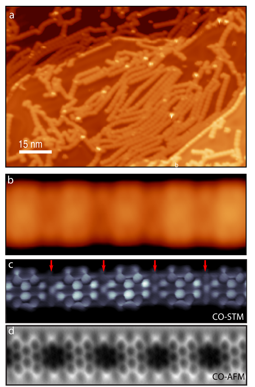
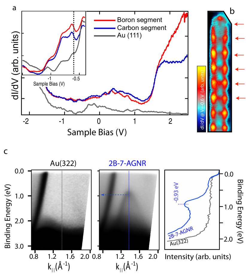
Figure 1a shows an overview of the resulting ribbons on the Au(111) surface. As reported in Refs. 15, 16, the on-surface reaction of precursor 1 is complete, and produces extended ribbons with a small internal contrast in STM images. A close-up view on a ribbon segment (Fig. 1b) highlights the distinctive topographic contrast of 2B-7-AGNRs, where borylated regions appear as slight depressions along the ribbon backbone. To enhance the resolution of the ribbon we functionalized the STM tip with a CO molecule 31 and mapped the tunneling current in a constant height image at very low bias 32. This method achieves high resolution images of the ring structure of the graphenoid backbone (Fig. 1c), which are comparable with constant-height AFM images (Fig. 1d). Interestingly, while the boron-regions are imaged as dark areas in AFM, they can be resolved in CO-STM, but with a lower contrast (red arrows in Fig. 1c). Although both imaging methods have some sensitivity to electronic states, they suggest that the borylated regions are lower 15 and, consequently, hint towards a stronger hybridization of boron atoms with the gold surface.
Valence band determination. We performed STS measurements on 2B-7-AGNR to determine the impact of the boron substitution on the 7-AGNR electronic structure. Figure 2a shows the dI/dV spectra obtained at the edges of the borylated (red) and carbon (blue) regions of the 2B-7-AGNRs and the reference spectrum of the clean Au(111) surface (grey). The most prominent feature is the presence of a strong onset at 1.6 V, similar to the case of the conduction bands in pristine 7-AGNR 33, 34. Thus, we attribute this onset to the conduction band of the borylated ribbon CB. The identical alignment of this band than in the pristine case suggests that no significant charge transfer with the gold surface is to be expected in the borylated ribbon. Above this onset the conductance in the carbon segments reaches a plateau, while on the borylated segments we detect a lager density of states at higher energies.
In contrast to pristine 7-AGNRs, the onset of the valence band (VB) is not easily distinguishable in dI/dV spectra of 2B-7-AGNRs 15, 16. However, we found evidence of the presence of occupied frontier bands from dI/dV spectra in constant-current (closed feedback) mode. The spectra (inset of Fig. 2a) shows an onset of dI/dV signal at -0.6 V, which extends to bias values below -1 V, both at the carbon and the borylated regions. The dI/dV signal associated to this band appears stronger at the edges and also shows some higher signal over the boron sites (Fig. 2b). However, this is far from representing the band’s real shape due to spurious effects regarding the different extension of the GNR orbitals into the vacuum 34. As we shall show later, the probable origin of the weak valence signal in dI/dV spectra as compared to the pristine version of 7-AGNR is a band order reversal with respect to the 7-AGNR band structure. This reversal is induced by boron states that selectively mix with the carbon -system, as we detailed in Ref. 17.
To explore the region of occupied bands of the borylated nanoribbons we also performed angle-resolved photoelectron spectroscopy of 2B-7-AGNRs on Au(322). The phoemission results resolve a clear dispersing band with an effective mass of 0.12 m and its onset at a binding energy of 0.93 eV (Fig. 2c). We note that the work function of this surface is 0.25 eV lower than that of Au(111) 25. Hence, if we consider that for weakly interacting adsorbates the bands shift according to changes in the work-function, these results would correspond to a band’s onset energy of 0.68 eV on the Au(111) surface. This value is close to the value observed in STS, although the low effective mass of the band´s electrons is intriguing. As we shall show later, DFT finds that this band corresponds instead to the VB-1 of the pristine ribbon, which is however not visible in STS due to its nodal-plane structure 34, 9, 35.
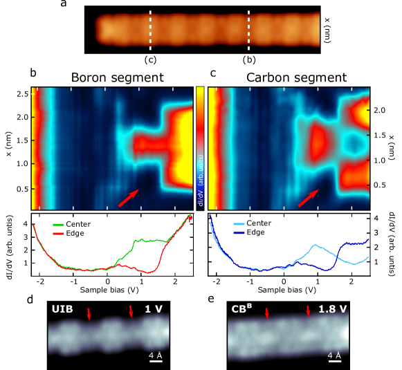
Impurity states of 2B-AGNR. The dI/dV spectra in Fig. 2a also show the presence of a broad conductance signal, between E and CB, which is absent in the electronic structure of the pristine 7-AGNR. To explore in more detail the origin of this broad feature, we present in Fig. 3b and 3c two stack plots of dI/dV spectra (spectral map) taken across the borylated and the carbon sections of the 2B-7-AGNR, respectively (Figure 3a). The spectral maps highlight the presence of a broad feature above 0.3 V, with maximum intensity at around 1 V, i.e. within the CB-VB band-gap, strongly localized at the center of the ribbon, and extending along the ribbon’s axis. Its energy and spatial distribution suggest that it corresponds to a new unoccupied impurity band (UIB) originated by the boron substitution. A similar feature was denominated acceptor band in Ref. 16.
Interestingly, the spectral maps of Fig. 3 show an evolution of features attributed to the Au(111) surface state (SS) in the proximity of the ribbon (red arrows in Figures 3b and c). The SS signatures gradually shift and merge with the UIB. This effect suggests a sizable hybridization of boron-rich states with the SS, which is consistent with the broad line width of the UIB.
Constant height dI/dV maps at the UIB’s maximum signal (1 V) and the CB’s onset show distinct modulations, both of which detail the absence of a nodal plane along the AGNR axis, and thus evidences the even symmetry of these bands across the ribbon (Fig. 3d and 3e). Furthermore, the edges of the ribbon are depleted of states at the borylated segments in both bands, whereas the carbon segments accumulate states, specially for the UIB-derived band. In spite of the hybridization with the SS, the dI/dV maps agree fairly well with the simulated local density of states (LDOS) maps for the unoccupied bands of an ribbon adsorbed on the Au(111) surface (shown in Fig. 4d-4f).
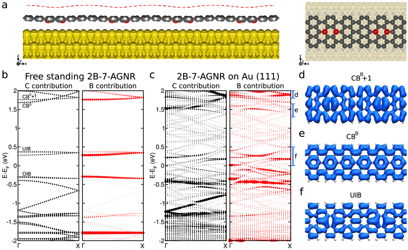
Density Functional Theory results. A better understanding of the electronic structure of the boron doped nanoribbons and their interaction with the underlying metal substrate is provided by ab initio simulations. In particular, we performed DFT calculations for 2B-7-AGNRs, both free standing and adsorbed on a Au(111) substrate. In the latter case, special care was taken to ensure a correct description of the Shockley state of the metal surface (more details in the methods section above). The optimized geometry of the 2B-7-AGNR/Au(111) system is shown in Figure 4a. The presence of the boron pairs induces a significant deformation of the nanoribbon: the borylated regions appear 0.3 Å closer to the metal surface, in close agreement with the results from Ref. 15. This deformation is absent in the free ribbon, and hence, reflects a sizable nanoribbon-metal hybridization. In the following we describe the main ingredients that characterize the band structure of the 2B-7-AGNRs.
In-gap impurity bands: Figure 4b shows the band structure of the free-standing nanoribbon projected onto carbon and boron orbitals, thus reflecting the contribution from different species to each band. Notice that this band structure has been computed using a unit cell that contains two 2B-defects in order to facilitate the comparison with the adsorbed case (Fig. 4a). The most characteristic feature is a pair of bands with large boron contribution, located close to the Fermi level (0.3 eV in Fig. 4b). They correspond to an occupied impurity-induced band (OIB) and an unoccupied impurity-induced band (UIB). The presence of these two bands at EF was already identified at low doping concentration in Ref. 17 (also shown in Fig. 5). Intriguingly, very little B content is present in the bands immediately below and above these impurity bands, i.e. in the delocalized frontier bands of the 2B-7-AGNR, whose origin will be discussed later in more detail. We also find an additional band with large B contribution at -1.9 eV. As in the case of both in-gap impurity states, this band is rather flat, denoting its large degree of localization at the 2B sites. This band was also identified in the high dilution limit in Ref. 17
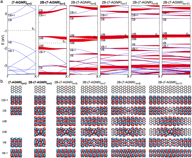
These two impurity bands can be rationalized by considering that boron states of neighboring 2B sites hybridize with each other and form these flat bands. For very low impurity concentration in a free-standing ribbon (e.g. large separation between 2B dopants, see Supporting Information in Ref. 17), two boron states lie very close to EF with a shape that resembles the impurity bands of the present case. In Fig. 5a we show the evolution of the band structure as the borylated moieties are approached. The two boron states found at EF for the diluted case (n=11) gradually increase their energy spacing as the boron moieties become closer than 7 unit cells of the pristine 7-AGNR, and develop a weak dispersion. Figure 5b shows the evolution of the wave functions of the localized boron states. As the 2B sites get closer the impurities’ wave functions overlap and become the new impurity bands (OIB and UIB) of the current (n=3) 2B-7-AGNR. From these results, we foresee that the OIB-UIB energy spacing can be tuned by adjusting the length of the carbon segments used for the on-surface reaction.
Interestingly, the wave-functions for the OIB and UIB of the 2B-7-AGNR (obtained at the point, shown in the second column of Figure 5 b) exhibit an even symmetry across the ribbon for both impurity states 17, in agreement with dI/dV maps of Fig. 3. At the point (Fig. 5) the OIB has a nodal plane in the middle of the 2B-defect, while UIB presents even parity with respect to the 2B-defect center. This contrasts with the apparent nodal plane observed in the experimental map of the UIB (Fig. 3d). The situation, however, is reversed as we move towards the Brillouin zone boundary (not shown in the figure). Hence, a direct comparison of experimental STS maps with wave-function isosurfaces of periodic systems at a particular point can lead to errors in the band assignment. We thus plot in Fig. 4(d-f) the computed LDOS maps of the unoccupied bands for the 2B-7-AGNR on the Au(111) surface, which can be more directly correlated with the dI/dV maps of Fig. 3. The even symmetry across the ribbon is maintained for the B-rich bands, while the low signal between the two B atoms of the UIB is now clearly reproduced by the simulations.
Band-reversal at the band-gap edges: Surprisingly, the original VB of the pristine 7-AGNR is absent in the band structure of the 2B-7-AGNR in Fig. 4b. Instead, the first carbon-rich ribbon state is a dispersing band, slightly below the OIB, which has the characteristic wave-function (plotted at in Fig. 5b) of the VB-1 of the pristine ribbon. This band is not affected by the presence of the boron impurities because its has odd symmetry across the ribbon axis 17, and presents a clear nodal plane along the axis, where the 2B moieties lie. The negligible interaction of VB-1 with the boron impurities is evident from Fig. 5b, where the corresponding wave-function is identical to that of the pristine ribbon and not affected by the change in the separation between the boron moieties. Additionally, this band has many nodal-planes along the ribbon, which explains why it is difficult to detect in normal STS measurements, as it is the case for the VB-1 of the pristine ribbons 34.
In contrast, the original VB is known to interact strongly with boron states because both have even symmetry across the ribbon. As previously reported17, this band is strongly scattered by 2B moieties and confined in the carbon 7-AGNR segments between them, appearing as quantized flat bands at lower energies. The quantized VB of the pristine ribbon appears in Fig. 5b, for the n=11 case, split in several modes with large B content. The VB band onset shifts down significantly as the distance between 2B moieties (i.e. the confined region) becomes smaller. For the n=3 case, the first VB derived QWS appears in Fig. 4b as a quite flat band at -1.3 eV with a moderate B content that indicates its hybridization with the 2B impurities.
The results in Fig. 5 also confirm that a similar reversal of frontier bands due to symmetry-selective band mixing applies to the conduction bands. The original CB of 7-AGNR is even across the ribbon and, thus, interacts with the 2B states, in contrast to the pristine CB+1, which is odd. However, the interaction is weaker in this case, and the pristine CB moves to lie slightly above the CB+1, which becomes the new frontier band. In contrast to the case of valence bands, the pristine CB was in this case the “hidden” band in STS spectra because of the numerous nodal planes along the ribbon 34, and the one usually detected was the CB+1, which has odd symmetry across and is not affected by the boron. This explain that in both pristine and borylated ribbons, the conduction band detected by STM, the CB+1, lies at the same position.
Adsorption on the Au(111) surface: When adsorbed on the Au(111) slab, the main ingredients of the electronic structure of the free-standing 2B-7-AGNRs can be still identified. One of the most significant changes though, is the mixing of the impurity bands with Au states. Figure 4c shows that UIB undergoes a larger distortion and mixture with Au states upon adsorption, resulting in a broad band of boron-rich states that accounts for its spectral line shape in our experiment.
In contrast, the dispersion of the carbon-rich bands and the OIB can still be recognized in the band plots, signaling their weaker hybridization with the states at the surface. We observe a small mixing between the originally orthogonal VB-1 and OIB, probably due to their proximity and the mediation of the metal. Since the OIB is a rather flat band, we conclude that the band resolved by ARPES in Fig.2c corresponds to the VB-1, while the one measured by STM in Fig. 2a is probably the OIB, because it appears modulated with the periodicity of the boron subunits.
4 Conclusions
In conclusion, we have studied the structural and electronic effects of a boron-substitution on armchair graphene nanoribbons. The resulting structures exhibit a high boron-dopant concentration and a well-defined periodicity. The most prominent change on the electronic structure of 2B-7-AGNRs is the introduction of two in-gap impurity bands, which arise from the overlap of nearby borylated moieties, and mix strongly with Au(111) surface states resulting in hybrid metal-ribbon states. The 2B dopants also cause a reversal of the carbon-rich bands at the gap edges, compared to the pristine 7-AGNR ribbon. This is caused by the symmetry selective mixing of bands with the states of the di-boron defect, which leads to quantum confinement of original VB and CB and their shift away from the gap. The new valence and conductance bands have a different symmetry both across and along the ribbon. Indeed, they correspond to the VB-1 and CB+1 of the pristine 7-AGNR. This is the reason for the previously reported 15, 16 disappearance of the VB from STS spectra. Our results further define basic rules for tuning the band structure of the ribbons: varying the distance between 2B groups can be employed to tune the gap between impurity bands; rotation of the 2B moiety with respect to the ribbon axis changes the symmetry of the carbon bands that they mix with, thus affecting the character of the frontier transport bands.
We acknowledge financial support from the Basque Government (Departamento de Industria, grant no. PI-2015-1-42, and Departamento de Educación and UPV/EHU, grant No. IT-756-13), and the Spanish Ministerio de Economía y Competitividad (Grants No. MAT2016-78293-C6, FIS2015-62538-ERC, FIS2017-83780-P), and the Maria de Maeztu Units of Excellence Programme MDM-2016-0618), the European Research Council (grant agreement no. 635919), and the European Regional Development Fund.
References
- Celis et al. 2016 Celis, A.; Nair, M. N.; Taleb-Ibrahimi, A.; Conrad, E. H.; Berger, C.; De Heer, W. A.; Tejeda, A. Graphene nanoribbons: Fabrication, properties and devices. J. Phys. D. Appl. Phys. 2016, 49, 143001
- Yang et al. 2007 Yang, L.; Park, C.-H. H.; Son, Y.-W. W.; Cohen, M. L.; Louie, S. G. Quasiparticle energies and band gaps in graphene nanoribbons. Phys. Rev. Lett. 2007, 99, 6–9
- Wakabayashi et al. 2010 Wakabayashi, K.; Sasaki, K.-i.; Nakanishi, T.; Enoki, T. Electronic states of graphene nanoribbons and analytical solutions. Sci. Technol. Adv. Mater. 2010, 11, 054504
- Cai et al. 2010 Cai, J.; Ruffieux, P.; Jaafar, R.; Bieri, M.; Braun, T.; Blankenburg, S.; Muoth, M.; Seitsonen, A. P.; Saleh, M.; Feng, X.; Mullen, K.; Fasel, R. Atomically precise bottom-up fabrication of graphene nanoribbons. Nature 2010, 466, 470–473
- Talirz et al. 2016 Talirz, L.; Ruffieux, P.; Fasel, R. On-Surface Synthesis of Atomically Precise Graphene Nanoribbons. Adv. Mater. 2016, 6222–6231
- Corso et al. 2018 Corso, M.; Carbonell-Sanromà, E.; de Oteyza, D. In On-surface synthesis II; de Oteyza, D., Rogero, C., Eds.; Springer: Switzerland, 2018; Chapter Bottom-up Fabrication of Atomically Precise Graphene Nanoribbons, pp 113–152
- Zhang et al. 2015 Zhang, H.; Lin, H.; Sun, K.; Chen, L.; Zagranyarski, Y.; Aghdassi, N.; Duhm, S.; Li, Q.; Zhong, D.; Li, Y.; Müllen, K.; Fuchs, H.; Chi, L. On-Surface Synthesis of Rylene-Type Graphene Nanoribbons. J. Am. Chem. Soc. 2015, 137, 4022–4025
- Chen et al. 2013 Chen, Y.-C.; de Oteyza, D. G.; Pedramrazi, Z.; Chen, C.; Fischer, F. R.; Crommie, M. F. Tuning the Band Gap of Graphene Nanoribbons Synthesized from Molecular Precursors. ACS Nano 2013, 7, 6123–6128
- Talirz et al. 2017 Talirz, L. et al. On-Surface Synthesis and Characterization of 9-Atom Wide Armchair Graphene Nanoribbons. ACS Nano 2017, 1380–1388
- Abdurakhmanova et al. 2014 Abdurakhmanova, N.; Amsharov, N.; Stepanow, S.; Jansen, M.; Kern, K.; Amsharov, K. Synthesis of wide atomically precise graphene nanoribbons from para-oligophenylene based molecular precursor. Carbon 2014, 77, 1187 – 1190
- Merino-Díez et al. 2017 Merino-Díez, N.; Garcia-Lekue, A.; Carbonell-Sanromà, E.; Li, J.; Corso, M.; Colazzo, L.; Sedona, F.; Sánchez-Portal, D.; Pascual, J. I.; De Oteyza, D. G. Width-Dependent Band Gap in Armchair Graphene Nanoribbons Reveals Fermi Level Pinning on Au(111). ACS Nano 2017, 11, 11661–11668
- de Oteyza et al. 2016 de Oteyza, D. G.; García-Lekue, A.; Vilas-Varela, M.; Merino-Díez, N.; Carbonell-Sanromà, E.; Corso, M.; Vasseur, G.; Rogero, C.; Guitián, E.; Pascual, J. I.; Ortega, J. E.; Wakayama, Y.; Peña, D. Substrate-Independent Growth of Atomically Precise Chiral Graphene Nanoribbons. ACS Nano 2016, 10, 9000–9008
- Ruffieux et al. 2016 Ruffieux, P.; Wang, S.; Yang, B.; Sánchez-Sánchez, C.; Liu, J.; Dienel, T.; Talirz, L.; Shinde, P.; Pignedoli, C. A.; Passerone, D.; Dumslaff, T.; Feng, X.; Müllen, K.; Fasel, R. On-surface synthesis of graphene nanoribbons with zigzag edge topology. Nature 2016, 531, 489–492
- Nguyen et al. 2016 Nguyen, G. D.; Toma, F. M.; Cao, T.; Pedramrazi, Z.; Chen, C.; Rizzo, D. J.; Joshi, T.; Bronner, C.; Chen, Y.-C.; Favaro, M.; Louie, S. G.; Fischer, F. R.; Crommie, M. F. Bottom-Up Synthesis of N = 13 Sulfur-Doped Graphene Nanoribbons. J. Phys. Chem. C 2016, 120, 2684–2687
- Kawai et al. 2015 Kawai, S.; Saito, S.; Osumi, S.; Yamaguchi, S.; Foster, A. S.; Spijker, P.; Meyer, E. Atomically controlled substitutional boron-doping of graphene nanoribbons. Nat. Commun. 2015, 6, 8098
- Cloke et al. 2015 Cloke, R. R.; Marangoni, T.; Nguyen, G. D.; Joshi, T.; Rizzo, D. J.; Bronner, C.; Cao, T.; Louie, S. G.; Crommie, M. F.; Fischer, F. R. Site-Specific Substitutional Boron Doping of Semiconducting Armchair Graphene Nanoribbons. J. Am. Chem. Soc. 2015, 137, 8872–8875
- Carbonell-Sanromà et al. 2017 Carbonell-Sanromà, E.; Brandimarte, P.; Balog, R.; Corso, M.; Kawai, S.; Garcia-Lekue, A.; Saito, S.; Yamaguchi, S.; Meyer, E.; Sánchez-Portal, D.; Pascual, J. I. Quantum Dots Embedded in Graphene Nanoribbons by Chemical Substitution. Nano Lett. 2017, 17, 50–56
- Carbonell-Sanromà et al. 2017 Carbonell-Sanromà, E.; Hieulle, J.; Vilas-Varela, M.; Brandimarte, P.; Iraola, M.; Barragán, A.; Li, J.; Abadia, M.; Corso, M.; Sánchez-Portal, D.; Peña, D.; Pascual, J. I. Doping of Graphene Nanoribbons via Functional Group Edge Modification. ACS Nano 2017, 11, 7355–7361
- Durr et al. 2018 Durr, R. A.; Haberer, D.; Lee, Y.-L.; Blackwell, R.; Kalayjian, A. M.; Marangoni, T.; Ihm, J.; Louie, S. G.; Fischer, F. R. Orbitally Matched Edge-Doping in Graphene Nanoribbons. J. Am. Chem. Soc. 2018, 140, 807–813
- Kawai et al. 2018 Kawai, S.; Nakatsuka, S.; Hatakeyama, T.; Pawlak, R.; Meier, T.; Tracey, J.; Meyer, E.; Foster, A. S. Multiple heteroatom substitution to graphene nanoribbon. Sci. Adv. 2018, eaar7181
- Cai et al. 2014 Cai, J.; Pignedoli, C. A.; Talirz, L.; Ruffieux, P.; Söde, H.; Liang, L.; Meunier, V.; Berger, R.; Li, R.; Feng, X.; Müllen, K.; Fasel, R. Graphene nanoribbon heterojunctions. Nat. Nanotechnol. 2014, 9, 896–900
- Chen et al. 2015 Chen, Y.-C.; Cao, T.; Chen, C.; Pedramrazi, Z.; Haberer, D.; de Oteyza, D. G.; Fischer, F. R.; Louie, S. G.; Crommie, M. F. Molecular bandgap engineering of bottom-up synthesized graphene nanoribbon heterojunctions. Nat. Nanotechnol. 2015, 10, 156–160
- Li et al. 2018 Li, J.; Merino-Díez, N.; Carbonell-Sanromà, E.; Vilas-Varela, M.; de Oteyza, D. G.; Peña, D.; Corso, M.; Pascual, J. I. Survival of spin state in magnetic porphyrins contacted by graphene nanoribbons. Sci. Adv. 2018, 4, eaaq0582
- Cao et al. 2017 Cao, T.; Zhao, F.; Louie, S. G. Topological Phases in Graphene Nanoribbons: Junction States, Spin Centers, and Quantum Spin Chains. Phys. Rev. Lett. 2017, 119, 076401
- Merino-Díez et al. 2018 Merino-Díez, N.; Li, J.; Garcia-Lekue, A.; Vasseur, G.; Vilas-Varela, M.; Carbonell-Sanromà, E.; Corso, M.; Ortega, J. E.; Peña, D.; Pascual, J. I.; de Oteyza, D. G. Unraveling the Electronic Structure of Narrow Atomically Precise Chiral Graphene Nanoribbons. J. Phys. Chem. Lett. 2018, 9, 25–30
- Soler et al. 2002 Soler, J. M.; Artacho, E.; Gale, J. D.; García, A.; Junquera, J.; Ordejón, P.; Sánchez-Portal, D. The SIESTA method for ab initio order- N materials simulation. J. Phys. Condens. Matter 2002, 14, 2745
- Giovannetti et al. 2008 Giovannetti, G.; Khomyakov, P. A.; Brocks, G.; Karpan, V. M.; van den Brink, J.; Kelly, P. J. Doping Graphene with Metal Contacts. Phys. Rev. Lett. 2008, 101, 026803
- Gonzalez-Lakunza et al. 2008 Gonzalez-Lakunza, N.; Fernández-Torrente, I.; Franke, K. J.; Lorente, N.; Arnau, A.; Pascual, J. I. Formation of Dispersive Hybrid Bands at an Organic-Metal Interface. Phys. Rev. Lett. 2008, 100, 156805
- Klimeš et al. 2010 Klimeš, J.; Bowler, D. R.; Michaelides, A. Chemical accuracy for the van der Waals density functional. J. Phys. Cond. Matt. 2010, 22, 022201
- García-Gil et al. 2009 García-Gil, S.; García, A.; Lorente, N.; Ordejón, P. Optimal strictly localized basis sets for noble metal surfaces. Phys. Rev. B 2009, 79, 075441
- Gross et al. 2011 Gross, L.; Moll, N.; Mohn, F.; Curioni, A.; Meyer, G.; Hanke, F.; Persson, M. High-Resolution Molecular Orbital Imaging Using a p -Wave STM Tip. Phys. Rev. Lett. 2011, 107, 086101
- Hieulle et al. 2018 Hieulle, J.; Carbonell-Sanromà, E.; Vilas-Varela, M.; Garcia-Lekue, A.; Guitián, E.; Peña, D.; Pascual, J. I. On-Surface Route for Producing Planar Nanographenes with Azulene Moieties. Nano Lett. 2018, 18, 418–423
- Ruffieux et al. 2012 Ruffieux, P.; Cai, J.; Plumb, N. C.; Patthey, L.; Prezzi, D.; Ferretti, A.; Molinari, E.; Feng, X.; Müllen, K.; Pignedoli, C. A.; Fasel, R. Electronic Structure of Atomically Precise Graphene Nanoribbons. ACS Nano 2012, 6, 6930–6935
- Söde et al. 2015 Söde, H.; Talirz, L.; Gröning, O.; Pignedoli, C. A.; Berger, R.; Feng, X.; Müllen, K.; Fasel, R.; Ruffieux, P. Electronic band dispersion of graphene nanoribbons via Fourier-transformed scanning tunneling spectroscopy. Phys. Rev. B 2015, 91, 045429
- Senkovskiy et al. 2018 Senkovskiy, B. V.; Usachov, D. Y.; Fedorov, A. V.; Haberer, D.; Ehlen, N.; Fischer, F. R.; Grüneis, A. Finding the hidden valence band of N = 7 armchair graphene nanoribbons with angle-resolved photoemission spectroscopy. 2D Mater. 2018, 5, 035007