First-principles calculations of iron-hydrogen reactions in silicon
Abstract
Controlling the contamination of silicon materials by iron, especially dissolved interstitial iron (Fei), is a longstanding problem with recent developments and several open issues. Among these we have the question whether hydrogen can assist iron diffusion, or if significant amounts of substitutional iron (Fes) can be created. Using density functional calculations we explore the structure, formation energies, binding energies, migration, and electronic levels of several FeH complexes in Si. We find that a weakly bound FeiH pair has a migration barrier close to that of isolated Fei and a donor level at eV. Conversely, FeiH is estimated at eV. These findings suggest that the hole trap at eV obtained by capacitance measurements should be assigned to FeiH2. FesH-related complexes show only deep acceptor activity and are expected to have little effect on minority carrier life-time in -type Si. The opposite conclusion can be drawn for -type Si. We find that while in H-free material Fei defects have lower formation energy than Fes, in hydrogenated samples Fes-related defects become considerably more stable. This would explain the observation of an EPR signal attributed to a FesH-related complex in hydrogenated Si, which was quenched from above 1000∘C to iced-water temperature. Published in Journal of Applied Physics123, 245703 (2018). https://doi.org/10.1063/1.5039647
I Introduction
Iron is a fundamental constituent of many tools and industrial equipments, it is present in silicon raw materials, and that makes Fe contamination of Si ingots virtually unavoidable.(Jastrzebski et al., 1994; Istratov, Hieslmair, and Weber, 2000) Stringent control of Fe impurities in Si is particularly critical in electronic- and solar-grade materials, as a donor level at eV from interstitial iron (Fei),(Feichtinger, Waltl, and Gschwandtner, 1978) leads to powerful minority carrier recombination activity in -type Si,(Istratov, Hieslmair, and Weber, 1999) most often the material of choice for the fabrication of Si solar cells.
Hydrogenation of Silicon wafers has been recurrently applied in order to passivate, or at least reduce, the recombination activity from several defects and contaminants, including iron and other transition metals.(Pearton and Tavendale, 1982; Singh, Fonash, and Rohatgi, 1986; Istratov, Hieslmair, and Weber, 2000; Peaker et al., 2012; Liu, Sun, and Macdonald, 2014; Scheffler, Kolkovsky, and Weber, 2015; Mullins et al., 2017) In Si photovoltaics this hydrogenation process is usually accomplished by means of depositing and firing a hydrogen-soaked SiNx layer on top of Si, which besides the surface-passivation effect, it also works as an anti-reflection coating for the front surface of the cell.(Jiang et al., 2003; Holt et al., 2003) Other types of hydrogen introduction for passivation treatments have also been considered, including proton implantation(Kouketsu and Isomae, 1996) or H-plasma exposure,(Pearton and Tavendale, 1984) but none is as convenient as the nitridation process.
The interaction between Fe and H in silicon has been addressed in the past. Early studies by Pearton and Tavendale(Pearton and Tavendale, 1984) reported the passivation of iron- and silver-related centers in -type samples exposed to Hydrogen plasma. Here, the introduction of the metallic impurities was accomplished by high-temperature evaporation, and from deep-level transient spectroscopy (DLTS), the suppression of an electrical level at eV, by the time connected to a Fe-O complex,(Wünstel and Wagner, 1981) after the H-plasma treatment was announced as an interaction between H and Fe. No direct interaction between H and interstitial Fe (Fei) was reported on these studies. More than a decade later, thermally stimulated capacitance (TSCAP) measurements performed by Sadoh et al.(Sadoh et al., 1997) using iron doped floating-zone -type Si that was subject to wet-etching, displayed the same level, which was then reassigned to a FeH complex. Annealing studies showed that after 30-minute treatments at , the level disappeared, suggesting a low binding energy between Fe and H species. Despite these conclusions, there was no direct evidence for the presence of either Fe or H in the ‘ eV’ center.
More recently, further evidence for a Fe-H complex in -type silicon was reported by Leonard and co-workers.(Leonard et al., 2015) The hydrogen was introduced into the samples from a silicon nitride layer grown by plasma enhanced chemical vapor deposition. After a reverse-bias annealing at about 100∘C, a hole trap was observed in the DLTS spectrum from samples with high concentrations of Fe and H. This trap was only stable up to 125∘C and it was related to a donor level at eV. The electronic signature of this trap coincided with that reported in Ref. Sadoh et al., 1997.
The interaction of hydrogen with iron-related defects such as the iron-boron (FeB) pair and Fei itself was also addressed by Kouketsu and Isomae.(Kouketsu and Isomae, 1996) In this case, hydrogen was introduced by proton implantation, leading different observations when compared to those where hydrogen plasma was used. Accordingly, along with the disappearance of the DLTS signals related to Fei and FeB, the emergence of two hole traps at eV and eV was observed. It was not clear though, whether these new traps arose from the reaction between H and Fei-related complexes, or on the other hand, from complexes involving H and intrinsic defects (resulting from the implantation damage), eventually combined with Fe.
The interaction of H with FeB pairs was also studied by Yakimov and Parakhonsky using wet-etching,(Yakimov and Parakhonsky, 1997) therefore avoiding implantation damage effects. Their results suggested that at room-temperature, the introduction of hydrogen actually leads to dissociation of the FeB pairs in the near surface layer, thus increasing the concentration of interstitial iron. The process leading to such dissociation is not well understood, and therefore it is worth of further investigation.
Electron paramagnetic resonance (EPR) was also employed in the study of H-passivation of Fe in Si. Accordingly, the existence of a FeH complex with a binding energy of eV and stable up to< C was inferred after comparing EPR spectra from Fe-doped and (Fe,H)-co-doped -type floating zone Si.(Takahashi and Suezawa, 1999) Interestingly, the EPR signal which was assigned to the FeH complex was isotropic ( symmetry). Unfortunately, the authors could not unambiguously demonstrate the presence of H atoms in the center, either from the EPR data or from local vibrational mode absorption using deuterated samples.
Theoretical work by the Estreicher group proposed two stable structures for the FeH complex, namely FeiH and FesH, involving interstitial and substitutional Fe, respectively.(Szwacki, Sanati, and Estreicher, 2008) Although under equilibrium conditions iron impurities are located at interstitial sites, there is evidence for the existence of substantial concentrations of iron substitutional (Fes) provided by emission channeling(Wahl et al., 2005; Silva et al., 2013) and Mössbauer spectroscopy.(Gilles, Schröter, and Bergholz, 1990; Langouche, 1992; Weyer et al., 1997, 1999; Yoshida et al., 2002; Y.Yoshida, Ogawa, and Arikawa, 2003) The FeiH model consists on a Fe-H dimer with trigonal symmetry, with the Fe atom placed at the hexagonal interstitial site, while H is located close to a neighboring tetrahedral interstitial site. This structure was anticipated to produce two electrical levels, a donor at and an acceptor at .(Szwacki, Sanati, and Estreicher, 2008) The authors also estimated an energy gain of eV for the reaction (assuming a bond-centered configuration for hydrogen and neutral defects only), consistent with the thermal stability of the ‘ eV’ trap (annealing temperature of about 175∘C) as reported by Sadoh et al.(Sadoh et al., 1997) This reaction is expected to be hindered in p-type Si due to electrostatic repulsion between and ions.
The second structure, , was found to comprise an iron atom locked at a substitutional site, with the hydrogen atom roaming almost freely around it. This model was assigned to the EPR spectra reported by Takakashi and co-workers,(Takahashi and Suezawa, 1999) conforming to the observed isotropic symmetry. was predicted to produce an acceptor level at . The estimated binding energy for this structure was approximately , also in good agreement with the 1.3 eV binding energy estimated from the ESR measurements(Takahashi and Suezawa, 1999). Despite the agreement, the EPR data was acquired in -type material and for these conditions the proposed FesH complex would be in a diamagnetic negative charge state, raising doubts to the correctness of this assignment.
While the early literature indicates a relatively low thermal stability for Fe-H complexes (the measured binding energies and annealing experiments on one hand,(Sadoh et al., 1997; Takahashi and Suezawa, 1999; Leonard et al., 2015) and the first-principles calculations by Szwacki et al.(Szwacki, Sanati, and Estreicher, 2008) on the other hand, suggest that these complexes can only survive to temperatures of at most ), more recently the solar-Si community has turned the attention to the effect of hydrogenation on Fe diffusivity and gettering at higher temperatures. For instance, Ref. Karzel et al., 2013 reports a prominent decrease in the concentration of Fei after exposing multicrystalline Si wafers to a microwave-induced remote hydrogen plasma, followed by H-effusion during 300-500∘C-anneals. This is a surprisingly stable process (when compared to H-passivation using etched samples), and it was tentatively explained as a consequence of an enhanced diffusion of Fei caused by the introduction of H, thus leading to a faster gettering kinetics.
On the other hand, Liu et al.(Liu, Sun, and Macdonald, 2014) questioned the picture of a H-enhanced diffusivity of Fei, arguing that if that was the case, any increase of the annealing temperatures should lead to the observation of further gettering of Fe. However, they report that at , the amount of dissolved iron reaches a minimum of about 1% of the original content, and recovers at higher temperatures. It was then suggested that up to , the formation of a Fe-H complex should account for the decrease of Fei, and above that temperature the dissociation of the complex becomes dominant. This view was latter revised after secondary-ion mass spectroscopy (SIMS) measurements combined with DLTS, annealing and analysis of the iron-decay kinetics.(Liu et al., 2016) From the observed accumulation of Fe at the SiNx capping layer, it was concluded that the iron reduction in the Si bulk takes place via gettering at the silicon nitride films. Hydrogenation of Fei at high-temperatures was ruled out based on the lack of electrical activity in the Si as monitored by DLTS. Further, upon removal of the SiNx, subsequent high-temperature anneals did not reveal any electrical activity either.
With these observations in mind, we endeavored to calculate the stability, electrical activity and migration ability of FeH-related complexes. After describing the methodology, we report on the atomistic structure and energetics of FeH defects, their electronic activity, thermal stability and hydrogen-assisted migration of interstitial iron. We end up with a discussion of the results and conclusions.
II Method
We employed the Vienna Ab-initio Simulation Package (VASP) code(Kresse and Hafner, 1993, 1994; Kresse and Furthmüller, 1996) to perform density functional calculations concerning the relative stability, formation energies, electrical levels and migration barriers of FeH complexes in Si. These calculations were based on the projector-augmented wave (PAW) (Blöchl, 1994) method using the generalized gradient approximated exchange-correlation functional of Perdew, Burke and Ernzerhof.(Perdew, Burke, and Ernzerhof, 1996) The PAW potentials for Fe, Si and H species were generated in the , and valence configurations, respectively. The Kohn-Sham states were expanded in plane-waves with a cut off energy of .
Our atomistic models for the defects under scrutiny were inserted on 216 Si atom supercells with a theoretical lattice parameter of Å. We employed a Monkhorst and Pack -point grid to sample the Brillouin zone.(Monkhorst and Pack, 1976) The structural optimization of our defect models was done through a conjugate gradient method, with a convergence threshold of eV/Å for the maximum force acting on the nuclei. The self-consistent electronic relaxation cycles were computed with an accuracy of .
We employed the marker method (Resende et al., 1999; Coutinho et al., 2003) to assess the electrical activity of the FeH complexes. The markers for the double acceptor, acceptor and donor levels are, respectively: , and .(Shiraishi et al., 1999; Feichtinger, Waltl, and Gschwandtner, 1978) The respective electron affinities () and ionization potentials () calculated using the same 216-Si supercells are: , and . The image-charge corrections for all the markers and defects under scrutiny were accounted for using the algorithm proposed by Freysoldt, Neugebauer and Van de Walle.(Freysoldt, Neugebauer, and de Walle, 2009) The marker method consists on a direct comparison between ionization potentials (or electron affinities) of the marker and that of the defect under scrutiny. While charge-corrections to the energies are of the order of hundreds of meV, these essentially cancel in the calculated electronic levels, becoming a few meV. The error bar of the calculated levels was estimated at about 0.1 eV. This figure was estimated by calculating the Fei and Fes levels, but instead of a defect marker, ionization energies and electron affinities of a bulk supercell were assumed as reference energies for the valence band top and conduction band bottom edges, respectively.
Formation energies of neutral defects, , where determined using the following expression:
| (1) |
where stands for the total energy of a neutral defective supercell made of atoms of species with chemical potential . Chemical potentials eV, eV and eV were obtained from bulk Si, iron disilicide () and a H2 molecule in a box, respectively. The formation energy of a defect in charge state has a dependence, where is the Fermi energy with respect to the valence band top. The calculation of was carried out combining Eq. 1 and the results from the marker method described above. See Ref. Coutinho et al., 2012 for further details.
Hydrogen-assisted migration of interstitial iron was also investigated. We employed a 7-image nudged elastic band (NEB) method(Henkelman, Uberuaga, and Jónsson, 2000) in order to estimate the migration/transformation barriers of FeH-related defects in the neutral and positive charge states. These are the relevant states to be considered in -type material.
III Results
III.1 Defect Structures
In order to determine the ground state structures of FeiH and FesH defects, we started from the relaxed structures of Fei and Fes, respectively, and introduced one or two hydrogen atoms at several possible sites, either bonding directly to the Fe atom along different directions, next to their silicon first neighbors, at second-neighboring Si-Si bond-center sites, or near the Fe-Si bond-center site.
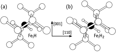
In line with the calculations reported by Szwaki et al.,(Szwacki, Sanati, and Estreicher, 2008) we predict that after trapping one hydrogen atom, the Fei atom becomes more stable near the hexagonal site while connecting to H along the trigonal axis. The resulting FeiH structure is depicted in Fig. 1(a). The defect is stable in the negative, neutral and positive charge states with spin 0, 1/2 and 1, respectively. The structure of the FeiH2 complex is analogous, with both H atoms bonded to Fei pointing towards opposite directions along a common axis. This is shown in Fig. 1(b), and the defect is also stable in the , , and charge states with spin 1/2, 1 and 1/2, respectively.
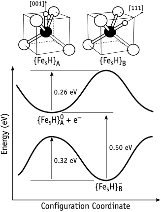
In the case of , we found it to be bistable, with H connecting to Fes along the direction in the neutral charge state, or along towards the tetrahedral interstitial site in the negative charge state. These structures are represented in the configuration coordinate diagram of Fig. 2, and are labeled as and respectively. They show spin 1/2 and 0, respectively, and each of them has a unique minimum in the potential energy surface: for the negatively charged defect, structural optimization initiated in the configuration relaxed into . Conversely, neutral is unstable and spontaneously relaxes to . The energy barriers for conversion between were calculated as 0.26 eV and 0.32 eV for neutral and negative charged defects. These figures are at variance with those obtained in Ref. Szwacki, Sanati, and Estreicher, 2008 (0.08 eV) and we can only suggest that in that work the Brillouin-zone sampling that was employed (-only) was not sufficiently dense considering the size of the supercells (64 atoms).
The capture of a second hydrogen atom by Fes also leads to two stable configurations in different charge states. For the neutral charge state we obtained a linear H-Fe-H configuration with both Fe-H bonds along the crystallographic axis, pointing towards opposite directions. This structure has high symmetry ( point group) and from inspection of the Kohn-Sham band structure with identified an empty double degenerate state in the upper half of the gap. We label this structure .
In the negative charge state the doublet state becomes partially populated and the structure undergoes a Jahn-Teller distortion. This translates into a eV relaxation energy and to the formation of a slanted Fe-H bond about 10∘ away from the axis. Several other low-energy distortions were found within 30 meV from the ground state. These consisted of pairs of Fe-H bonds oriented close to and , like in and , respectively. All non-linear H-Fe-H defects (including the ground state) were found with spin 1/2, and because they are all nearly degenerate, we refer to them as . Interestingly, the transformation barrier between these low-symmetry structures was found to be about 50 meV, indicating that the H atoms can roam almost freely around the Fes impurity, even at cryogenic temperatures.
In the double negative charge state, the Jahn-Teller distortion becomes stronger and both Fes-H bonds pointed approximately along orthogonal directions. The resulting diamagnetic state was found more stable than the paramagnetic linear structure with spin-1 by 0.29 eV. The reorientation of a Fes-H bond now involves surmounting a barrier of 0.12 eV. All Fe-H bond lengths in FesHn defects were in the range of 1.52-1.55 Å.
Besides the electronic energy (enthalpy), at high temperatures the entropy may impact on the relative stability of defects, and here the most important contributions are from configurational and vibrational degrees of freedom. Sanati and Estreicher found that vibrational entropy can stabilize light impurities in silicon by eV after ramping up the temperature by up to K.(Sanati and Estreicher, 2003) Assuming that the magnitude of Fe-H vibrational frequencies from and are not very different, the vibrational entropy difference is expected to be minute. Configurational entropy is normally not considered because it is difficult to estimate analytically except for very simple structures.(Estreicher et al., 2004) Within the Boltzmann framework, the configurational entropy difference between structures and is about eV/K, which translates into a mere 27 meV for K. Although a detailed account of entropy effects is outside the scope of this work, the picture just presented should not be generalized, and we should bear in mind that entropy could have a stronger influence, particularly when comparing energies of defects with different stoichiometry and lattice locations.
III.2 Electronic levels
The donor level of interstitial iron in silicon has been experimentally determined at eV.(Feichtinger, Waltl, and Gschwandtner, 1978) We investigated the reaction of H with Fei in terms of the resulting electronic activity. Since Fei is displaced from the tetrahedral site to the hexagonal site upon bonding with one or two H atoms, the electronic activity of FeiH complexes is expected to differ significantly from that of isolated Fei. In fact, we found that besides donor activity, both FeiH and FeiH2 complexes are acceptors. For the pair we obtain and levels at eV and eV. On the other hand, for we calculated and levels at eV and eV, respectively. No further levels were found for FeiHn defects. Although our results for are not far from previous theoretical reports,(Szwacki, Sanati, and Estreicher, 2008) the level seems too deep to be connected to the ‘ eV’ trap of Ref. Sadoh et al., 1997. Alternatively, shows a transition at eV, i.e. about the right placement within the gap, and therefore, must be considered as potentially accountable for the above trap as well. We will come back to this issue in Section III.4.
Now we turn to the interactions between H and substitutional iron. For and we obtained vertical transitions at and . However, we note that and are unstable, and the relevant thermodynamic acceptor level of FesH must be calculated from ground state energies. Hence, we obtain FesH at eV (see Fig. 2). Previous first-principles calculation(Szwacki, Sanati, and Estreicher, 2008) assigned FesH in the neutral charge state to an isotropic spin-1/2 EPR spectrum observed in -type material at a temperature as low as 10 K.(Takahashi and Suezawa, 1999) The location of the FesH level implies that under these conditions, the defect would be found in a diamagnetic negative charge state, and therefore undetectable by EPR. We could not find a second acceptor level for FesH. Hence, the assignment of the EPR data should be revised and further work is needed to clarify this point.
For FesH2 we anticipate first and second acceptor levels at and , respectively. It is noteworthy that the second electron trap is deeper than the first, i.e. FesH2 shows an inverted ordering of the acceptor levels. This is commonly referred to as negative- and arrises from a strong relaxation energy along the capture sequence, which surmounts the Coulomb repulsion between both captured electrons. Accordingly, in the neutral charge state FesH2 adopts structure A. This structure can capture a free-electron with a binding energy of 0.21 eV. After trapping the first electron, the structure quickly changes to , where some of the relaxation energy is effectively converted to an increase of the Coulomb attraction for the second electron, leading to a binding energy of 0.30 eV. The consequence of the negative- ordering of levels is that, under equilibrium conditions, it is energetically favorable to form a pair of and states than two structures (irrespectively of the Fermi level position). Hence, FesH2 has an occupancy level that is located half-way between the first and second acceptor levels, i.e. FesH2 eV. All calculated electrical levels are shown in Table 1.
| FeiH | 0.22 | 0.50 | |
|---|---|---|---|
| FeiH2 | 0.29 | 0.33 | |
| FesH | 0.50 | ||
| FesH2 | 0.30 | 0.21 |
III.3 Binding energies and doping effects
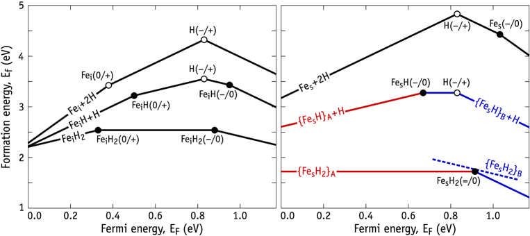
The diagrams presented in Figure 3 show formation energies of several defect sets involving one Fei impurity plus two interstitial H atoms (left), in comparison with one Fes impurity plus two interstitial H atoms (right) as a function of the Fermi energy. On each diagram the stoichiometry is conserved. The formation energy (vertical) scales are identical for a convenient comparison. Each sequence of connected segments relates to a particular set involving a FeiHn or FesHncomplex plus remote interstitial H atoms. The formation energy is proportional to , with and being the net charge of the whole defect set and Fermi level, respectively. Hence, positive-, zero- and negative-sloped segments refer to defect sets with net positive, neutral and negative charge, respectively. For instance, for FeiH plus a remote H atom (on the left diagram), as the Fermi energy goes from the valence band top () to the conduction band bottom ( eV), the sequence is: (net charge ); (net charge ); (net charge ); (net charge ). Hence, each kink between adjacent segments corresponds to a particular transition level identified in the Figure. We note that transition levels of Fei and interstitial H are measured. The latter is a negative- defect with donor and acceptor levels at eV and eV, leading to a occupancy level at eV.(Holm, Nielsen, and Nielsen, 1991; Johnson, Herring, and de Walle, 1995; Nielsen et al., 1999, 2002) Positive and negatively charged H defects are more stable at the bond-center () and tetrahedral interstitial sites (), respectively. The neutral charge state (used to calculate the formation energy in Eq. 1) was found more stable in the bond-center site (H). Experimental and calculated levels are highlighted by open and closed circles on both diagrams. Finally, on the diagram related to FesHn defects, we made use of color to distinguish A and B structures of FesH and FesH2 complexes.
Looking at the diagram on the left-hand side of Figure 3 we conclude that the capture of atomic H by Fei is an energetically favorable process regardless of the Fermi level position. The energy drop of the formation energy as we move from the upper segments () down to the lower segments (), represents the binding energy of the reaction , with or 1. In intrinsic material (considering the Fermi level to be approximately at mid-gap), the capture of H by Fei corresponds to an energy gain of . The capture of a second hydrogen atom corresponds to an energy gain of eV, leading to a total binding energy of to form a neutral complex. In p-type materials these reactions become less exothermic and the formation of FeiHn complexes becomes less likely. Hydrogenation of Fei is further hindered in -type Si due to the fact that both H and FeiHn complexes are deep donors, implying a long-range Coulomb repulsion between reactants. On the other hand, in n-type Si there is no Coulomb barrier for the reaction and the energy drop is . The reaction with a second hydrogen atom has a binding energy of 0.75 eV, but it is likely to be inhibited by repulsion between and . In summary, hydrogenation of interstitial iron in Si leads to FeiHn complexes whose binding energies are low, and they are compatible with the the annealing temperature of 125-175∘C of the FeH-related complex reported in Refs. Sadoh et al., 1997 and Leonard et al., 2015.
The diagram on the right-hand side of Figure 3 immediately suggests that H binds strongly to Fes, regardless of the doping type. In n-type Si the binding energies are eV, in excellent agreement with the measured binding energy of 1.3 eV for a FeH-related complex in -type Si, where Fe was suggested to be at the substitutional site.(Takahashi and Suezawa, 1999) In the lower part of the right diagram we also represent the formation energy of the negatively charged , just above the negative- transition at eV. This is show as a dashed line to stress its metastable character.
A more judicious inspection of Figure 3 allows us to conclude that, while in hydrogen-free material iron impurities have a lower formation energy at the interstitial site, in H-doped Si, the lower formation energy complexes are those involving substitutional iron. This suggests that even in -type Si, high temperature anneals (maybe with optical excitation in order to avoid Coulomb repulsion by changing the charge state of either H or Fe impurities), may be able to convert highly mobile and recombination active Fei impurities into stable and low-recombination active Fes impurities, where H atoms act as catalysts. Although we are not the first to realize this possibility,(Szwacki, Sanati, and Estreicher, 2008) it lacked theoretical support and it has been overlooked by the solar-Si community.
III.4 H-assisted diffusivity of iron
Bearing in mind the observation of the enhancement of Fe-gettering upon introduction of hydrogen (see for instance Refs. Karzel et al., 2013; Liu, Sun, and Macdonald, 2014; Liu et al., 2016), and considering the high thermal stability of the species (or phase) holding the Fe (which survives to temperatures above 500∘C), we investigated an eventual enhanced migration of assisted by H. This could lead to a faster formation of iron precipitates or out-diffusion from the Si. For the we considered a simple interstitial mechanism through the hexagonal site. In the case , the defect was found to travel as a molecule, also through neighboring hexagonal sites. As we mentioned before, a total of 7 NEB images were considered in order to determine the saddle point along the minimum energy path. The calculated migration barriers are , and for , and respectively. The barrier for migration of is in very good agreement with the measurements, which is about 0.6 eV (see Ref. Istratov, Hieslmair, and Weber, 1999 and references therein). Both and have migration barriers comparable to that of interstitial iron, and in p-type Si they are considerably larger than the binding energy of H to Fei. These results suggest that hydrogen, if able to attach to Fei, does not enhance its diffusivity.
IV Discussion and conclusions
We calculated the structure, formation energies, binding energies, and electronic levels of several FeH complexes in Si. and 2 defects consist on Fe-H and H-Fe-H pseudo-molecules, respectively, with the Fe and H atoms being located close to hexagonal and tetrahedral interstitial sites of the lattice. The modest binding energies of the H atoms to Fei seem consistent with the annealing temperature in the range of 125-175∘C reported for a hole trap at eV and assigned to an iron-hydrogen complex.(Sadoh et al., 1997; Szwacki, Sanati, and Estreicher, 2008; Leonard et al., 2015) However, an assignment to FeiH (with a single H atom) conflicts with its predicted migration barrier, which is close to that of Fei. Accordingly, both defects are expected to anneal out at close temperatures (just above room temperature). For the same reasons, complexes are not able to account for the reduction of upon annealing hydrogenated multicrystalline wafers in the temperature range of 700-900.(Karzel et al., 2013; Liu, Sun, and Macdonald, 2014; Liu et al., 2016)
FeiH and FeiH2 complexes were predicted to be simultaneously deep donors and acceptors, and therefore are not expected to substantially decrease the recombination activity of Fe in Si. The calculated levels and binding energies suggest that the donor level measured at eV from Refs. Sadoh et al., 1997 and Leonard et al., 2015 is likely to arise from a FeiHn complex involving 2 or more H atoms. The FeiH transition is predicted at eV, while FeiH is anticipated to occur close to mid-gap.
Substitutional iron and FesHn complexes are acceptors. No donor levels were found for these defects. For the pair we obtain a single acceptor level close to mid-gap. While this result is in line with Ref. Szwacki, Sanati, and Estreicher, 2008, it is not regarding the calculated barrier for H motion around the Fes impurity. In that work, the barrier was estimated to be as low as 0.08 eV, allowing the assignment of neutral to an isotropic EPR center observed in -type Si.(Takahashi and Suezawa, 1999) Our results do not corroborate this view. The calculated barrier for Fe-H bond reorientation is anticipated to be as high as 0.26 eV, which is not compatible with a fast-orbiting H atom and a motional-averaged tetrahedral symmetry at K. Further, the near mid-gap location of the calculated deep acceptor means that in -type material the stable state is diamagnetic FesH- (undetectable by EPR).
Regarding FesH2, we found a -aligned H-Fe-H linear structure in the neutral charge state. The point symmetry of the defect is and it has an empty doublet in the gap. Negative and double negative charge states are sensitive to Jahn-Teller distortions. The negatively charged defect is particularly interesting as it shows several possible low energy configurations with different angles between Fe-H bonds, differing by at most 30 meV in their relative energy and separated by reorientation barriers as shallow as 50 meV. Based on these findings, we suggest that the FeH-related EPR signal from Ref. Takahashi and Suezawa, 1999 arises from FesH or other FesHn complex with . The later option is perhaps the most probable as FesH2 is a negative- complex with a metastable negative state (see dashed line segment on the right diagram of Figure 3).
Figure 3 shows that the formation energy of Fei in non-hydrogenated Si is lower than that of Fes by about 0.5 eV. This explains the preference of iron to occupy interstitial sites. However, in the presence of hydrogen the formation of Fes-related complexes becomes favorable. This could explain the formation of large amounts of FesH-related defects in hydrogenated Si, as detected by EPR after quenching the samples from 950-1250∘C to 0∘C.(Takahashi and Suezawa, 1999)
Acknowledgements
This work was funded by the Fundação para a Ciência e a Tecnologia (FCT) under projects PTDC/CTM-ENE/1973/2012 and UID/CTM/50025/2013, and funded by FEDER funds through the COMPETE 2020 Program. Computer resources were provided by the Swedish National Infrastructure for Computing (SNIC) at PDC.
References
- Jastrzebski et al. (1994) L. Jastrzebski, J.Lagowski, W. Henley, and P. Edelman, MRS Proceedings 354, 405 (1994).
- Istratov, Hieslmair, and Weber (2000) A. A. Istratov, H. Hieslmair, and E. R. Weber, Applied Physics A 70, 489 (2000).
- Feichtinger, Waltl, and Gschwandtner (1978) H. Feichtinger, J. Waltl, and A. Gschwandtner, Solid State Communications 27, 867 (1978).
- Istratov, Hieslmair, and Weber (1999) A. A. Istratov, H. Hieslmair, and E. R. Weber, Applied Physics A 69, 13 (1999).
- Pearton and Tavendale (1982) S. J. Pearton and A. J. Tavendale, Physical Review B 26, 7105 (1982).
- Singh, Fonash, and Rohatgi (1986) R. Singh, S. J. Fonash, and A. Rohatgi, Applied Physics Letters 49, 800 (1986).
- Peaker et al. (2012) A. R. Peaker, V. P. Markevich, B. Hamilton, G. Parada, A. Dudas, A. Pap, E. Don, B. Lim, J. Schmidt, L. Yu, Y. Yoon, and G. Rozgonyi, physica status solidi (a) 209, 1884 (2012).
- Liu, Sun, and Macdonald (2014) A. Liu, C. Sun, and D. Macdonald, Journal of Applied Physics 116, 194902 (2014).
- Scheffler, Kolkovsky, and Weber (2015) L. Scheffler, V. Kolkovsky, and J. Weber, Journal of Applied Physics 117, 085707 (2015).
- Mullins et al. (2017) J. Mullins, S. Leonard, V. P. Markevich, I. D. Hawkins, P. Santos, J. Coutinho, A. G. Marinopoulos, J. D. Murphy, M. P. Halsall, and A. R. Peaker, physica status solidi (a) 214, 1700304 (2017), 1700304.
- Jiang et al. (2003) F. Jiang, M. Stavola, A. Rohatgi, D. Kim, J. Holt, H. Atwater, and J. Kalejs, Applied Physics Letters 83, 931 (2003).
- Holt et al. (2003) J. K. Holt, D. G. Goodwin, A. M. Gabor, F. Jiang, M. Stavola, and H. A. Atwater, Thin Solid Films 430, 37 (2003), proceedings of the Second International Conference on Cat-CVD (Hot Wire CVD) Process.
- Kouketsu and Isomae (1996) M. Kouketsu and S. Isomae, Journal of Applied Physics 80, 1485 (1996).
- Pearton and Tavendale (1984) S. J. Pearton and A. J. Tavendale, Journal of Physics C: Solid State Physics 17, 6701 (1984).
- Wünstel and Wagner (1981) K. Wünstel and P. Wagner, Solid State Communications 40, 797 (1981).
- Sadoh et al. (1997) T. Sadoh, K. Tsukamoto, A. Baba, D. Bai, A. Kenjo, T. Tsurushima, H. Mori, and H. Nakashima, Journal of Applied Physics 82, 3828 (1997).
- Leonard et al. (2015) S. Leonard, V. P. Markevich, A. R. Peaker, B. Hamilton, and J. D. Murphy, Applied Physics Letters 107, 032103 (2015).
- Yakimov and Parakhonsky (1997) E. B. Yakimov and A. L. Parakhonsky, Solid State Phenomena 57-58, 383 (1997).
- Takahashi and Suezawa (1999) T. Takahashi and M. Suezawa, Physica B: Condensed Matter 273–274, 445 (1999).
- Szwacki, Sanati, and Estreicher (2008) N. G. Szwacki, M. Sanati, and S. K. Estreicher, Physical Review B 78, 113202 (2008).
- Wahl et al. (2005) U. Wahl, J. G. Correia, E. Rita, J. P. Araújo, and J. C. Soares (The ISOLDE Collaboration), Physical Review B 72, 014115 (2005).
- Silva et al. (2013) D. J. Silva, U. Wahl, J. G. Correia, and J. P. Araújo, Journal of Applied Physics 114, 103503 (2013).
- Gilles, Schröter, and Bergholz (1990) D. Gilles, W. Schröter, and W. Bergholz, Physical Review B 41, 5770 (1990).
- Langouche (1992) G. Langouche, Hyperfine Interactions 72, 215 (1992).
- Weyer et al. (1997) G. Weyer, S. Degroote, M. Fanciulli, V. N. Fedoseyev, G. Langouche, V. I. Mishin, A.-M. V. Bavel, A. Vantomme, and the ISOLDE Collaboration, in Defects in Semiconductors 19, Materials Science Forum, Vol. 258 (Trans Tech Publications, 1997) pp. 437–442.
- Weyer et al. (1999) G. Weyer, A. Burchard, M. Fanciulli, V. N. Fedoseyev, H. P. Gunnlaugsson, V. I. Mishin, and R. Sielemann, Physica B: Condensed Matter 273, 363 (1999).
- Yoshida et al. (2002) Y. Yoshida, Y. Kobayashi, A. Yoshida, X. Diao, S. Ogawa, K. Hayakawa, K. Yukihira, F. Shimura, and F. Ambe, Hyperfine Interactions 141, 157 (2002).
- Y.Yoshida, Ogawa, and Arikawa (2003) Y.Yoshida, S. Ogawa, and K. Arikawa, Physica B: Condensed Matter 340, 605 (2003), proceedings of the 22nd International Conference on Defects in Semiconductors.
- Karzel et al. (2013) P. Karzel, A. Frey, S. Fritz, and G.Hahn, Journal of Applied Physics 113, 114903 (2013).
- Liu et al. (2016) A. Y. Liu, C. Sun, V. P. Markevich, A. R. Peaker, J. D. Murphy, and D. Macdonald, Journal of Applied Physics 120, 193103 (2016).
- Kresse and Hafner (1993) G. Kresse and J. Hafner, Physical Review B. 47, 558 (1993).
- Kresse and Hafner (1994) G. Kresse and J. Hafner, Physical Review B 49, 14251 (1994).
- Kresse and Furthmüller (1996) G. Kresse and J. Furthmüller, Physical Review B 54, 11169 (1996).
- Blöchl (1994) P. E. Blöchl, Physical Review B 50, 17953 (1994).
- Perdew, Burke, and Ernzerhof (1996) J. P. Perdew, K. Burke, and M. Ernzerhof, Physical Review Letters 77, 3865 (1996).
- Monkhorst and Pack (1976) H. J. Monkhorst and J. D. Pack, Physical Review B 13, 5188 (1976).
- Resende et al. (1999) A. Resende, R. Jones, S. Öberg, and P. R. Briddon, Physical Review Letters 82, 2111 (1999).
- Coutinho et al. (2003) J. Coutinho, V. J. B. Torres, R. Jones, and P. R. Briddon, Physical Review B 67, 035205 (2003).
- Shiraishi et al. (1999) M. Shiraishi, J.-U. Sachse, H. Lemke, and J. Weber, Materials Science and Engineering: B 58, 130 (1999).
- Freysoldt, Neugebauer, and de Walle (2009) C. Freysoldt, J. Neugebauer, and C. G. V. de Walle, Physical Review Letters 102 (2009), 10.1103/physrevlett.102.016402.
- Coutinho et al. (2012) J. Coutinho, V. P. Markevich, A. R. Peaker, B. Hamilton, S. B. Lastovskii, L. I. Murin, B. J. Svensson, M. J. Rayson, and P. R. Briddon, Physical Review B 86 (2012), 10.1103/physrevb.86.174101.
- Henkelman, Uberuaga, and Jónsson (2000) G. Henkelman, B. P. Uberuaga, and H. Jónsson, The Journal of Chemical Physics 113, 9901 (2000).
- Sanati and Estreicher (2003) M. Sanati and S. K. Estreicher, Solid State Communications 128, 181 (2003).
- Estreicher et al. (2004) S. K. Estreicher, M. Sanati, D. West, and F. Ruymgaart, Physical Review B 70, 125209 (2004).
- Holm, Nielsen, and Nielsen (1991) B. Holm, K. B. Nielsen, and B. B. Nielsen, Physical Review Letters 66, 2360 (1991).
- Johnson, Herring, and de Walle (1995) N. Johnson, C. Herring, and C. V. de Walle, Physical Review Letters 74, 1889 (1995).
- Nielsen et al. (1999) K. B. Nielsen, B. B. Nielsen, J. Hansen, E. Andersen, and J. U. Andersen, Physical Review B 60, 1716 (1999).
- Nielsen et al. (2002) K. B. Nielsen, L. Dobaczewski, S. Søgård, and B. B. Nielsen, Physical Review B 65, 075205 (2002).