∎
Tel.: +49-211-81-12317
11email: step.schiller@hhu.de
Simulation of force-insensitive optical cavities in cubic spacers
Abstract
We analyze the properties of optical cavities contained in spacers with approximate octahedral symmetry and made of different materials, following the design of Webster and Gill (S. Webster, P. Gill, Optics Letters 36(18), 3572 (2011)). We show that for isotropic materials with Young’s modulus less than GPa, the Poisson’s ratio must lie in a “magic” range in order to null the influence of the forces supporting the spacer. This restriction can be overcome with the use of anisotropic materials such as silicon. A detailed study aiming at identification of all suitable crystal orientations of silicon with respect to the resonator body is performed and the relation to the Poisson’s ratio and the Young’s modulus along these orientations is discussed. We also perform an analysis of the sensitivity of the cavity performance to errors in spacer manufacturing. We find that the orientation of the [110] or [100] crystallographic directions oriented along one of the three optical axes of the resonator provides low sensitivities to imprecise manufacturing and interesting options for fundamental physics experiments.
Keywords:
vibration insensitive resonator single-crystal silicon cryogenic optical resonator finite element analysis ultra-stable cavity1 Introduction
Optical Fabry-Pérot resonators are widely used in different fields of optics and metrology. As passive optical resonators they can provide the frequency reference for obtaining laser waves with ultra-stable frequencies for interrogation of transitions in atomic clocks Huntemann2016 ; Ludlow2015 ; Nicholson2015 , for gravitational wave detectors, or for fundamental tests of space-time structure Antonini2005 ; Eisele2009 ; Wiens2016 . Transfer of the frequency stability of laser waves into the microwave region potentially enables their application in radars and in navigation of deep space probes. High demands on frequency stability of laser light set forth by these applications require an optical resonator with a low sensitivity to vibrations.
Optical resonators are usually made of a spacer and two mirrors optically contacted to it. The frequency stability of such a resonator is determined, once evacuated, by the length stability of the resonator’s spacer. Vibrations transferred from the surroundings to the resonator change the distance between the mirrors and tilt them, degrading the frequency stability that it can provide. To fulfill the requirement of low vibration sensitivity a careful design of the shape of the resonator and of the supporting frame is needed.
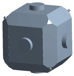
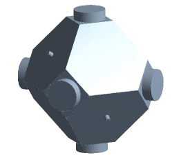
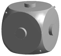
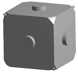
The design with the lowest sensitivity to vibrations so far was presented by Webster and Gill Webster2011 . The cavity structure (Fig. 1, top row) consists of a cube-shaped body made of ultra-low expansion glass ULE material with a side length of 50 mm. It is held inside a frame (not shown in the figure) by four supports acting at four tetrahedrically oriented cube vertices. Three cavities are contained in the body. The cubic (more precisely: octahedral) symmetry of the cube-like spacer causes, upon action of a body force density (gravity or acceleration) oriented in arbitrary direction, an equal displacement of the centers of opposing faces, and therefore zero differential displacement. This makes the three cavities (completely) insensitive to accelerations along any axis. Experimentally, finite acceleration sensitivities are observed: of the three sensitivity coefficients, the smallest was , the largest . Values of this order can be explained by imperfections in fabrication or mounting.
Furthermore, the cube vertices are truncated to a depth of 6.7 mm. This value was determined by Finite Element Analysis (FEA) simulations and ensures that the external forces acting at the support points, if equal, do not shift the position of the centers of the faces of the cube. This means that the three cavity lengths are insensitive to the support forces.
The material ULE has the advantageous property of a zero Coefficient of Thermal Expansion (CTE) at or near room temperature and therefore makes the resonator insensitive to thermal fluctuations. The drawback of ULE is its slow dimensional change due to its amorphous nature and the moderate Young’s modulus 67.6 GPa, a value that is relevant if one considers deviations of the spacer from ideal symmetry (see Sec. 6). Another fundamental limitation is the thermal Brownian noise of the ULE spacer Numata2004a ; Notcutt2006 . The mirror substrates, usually made of the same or from a similar material (fused silica), also contribute to the thermal noise Davila2017 .
Reduction of the operating temperature of resonators down to cryogenic temperatures is an approach that can reduce thermal noise Numata2004a . This has motivated the development of optical resonators cooled to cryogenic temperature Seel1997 . Cryogenic resonators operated at particular temperatures or close to zero absolute temperature also exhibit an ultra-low CTE, which relaxes the requirements on temperature stability Matei2017 ; Zhang2017 ; Wiens2014 ; Wiens2015 ; Seel1997 . High-performance cryogenic optical resonators have so far been crystals, which also enjoy the advantage of a long-term drift orders of magnitude smaller than ULE Wiens2016 ; Hagemann2014 .
In our work we present an analysis of the extension of the design of Webster and Gill Webster2011 to other materials beside ULE, in particular to materials that may be used advantageously at cryogenic temperatures. Because of the vibrational noise present in closed-cycle cryostats, it is particularly important to develop resonators with low acceleration sensitivity. In addition, the analysis seeks to answer the question whether it is possible to achieve an even lower acceleration sensitivity than possible with ULE when considering the influence of manufacturing errors.
2 Spacer geometry and modeling method
The main goal of the modeling is to find shapes and materials that lead to an insensitivity of the cavities contained in the cubic spacer to the strength of the forces acting on four vertices of the spacer. The sensitivity to acceleration arises automatically from the assumed octahedral symmetry of the spacer, and requires, at a first glance, no particular simulation. However, when there are deviations from symmetry, simulations allow to determine the acceleration sensitivity. We performed simulations using a commercial FEA software (Ansys). The FEA computation yields the fractional length change of each optical cavity upon application of a set of forces.
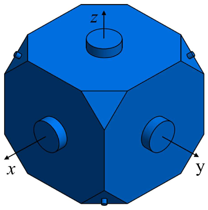
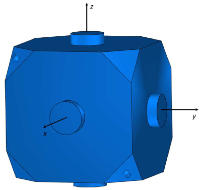
For concreteness, we chose the same dimensions for the spacer block as in Webster2011 : a cube with side length mm. Its density and mass are denoted by and , respectively. The edges of the cube lie along the space-fixed coordinate system axes Although only a single cavity, here the -cavity, is usually of interest, three mutually orthogonal cavities are formed by three through holes along the directions , so as to preserve octahedral symmetry. For concreteness, they have mm radius. A total of six mirror substrates of the same material as the block, having a diameter of mm and a thickness of mm, are attached to the end faces of the spacer. The substrates and the block are assumed to form a single unit (see Fig. 1).
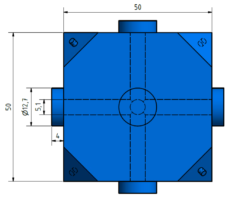
No pumping holes were included in the simulation. Since in the actual manufacturing the hole diameter could be chosen small, we expect that its effect on the mechanical properties would be minor. The eight corners of the cavity are truncated to a depth which is a free parameter.
The cavity is always simulated with four “holding” forces applied normal to four of the truncated corners. They each have an arbitrarily chosen but realistic magnitude of N, and are applied via four cylindrically shaped supports (here, having mm diameter) rigidly attached to the resonator at the four corners with a tetrahedral symmetry. We consider two cases:
(1) the application of only the four holding forces , i.e. gravity is ignored. The sensitivity to support force strength, , is calculated.
(2) In presence of , an additional acceleration acting along is applied. This simulates acceleration of the cavity support (and thus of the cavity body) or the gravitational acceleration. For this case we define the acceleration sensitivity , where is the additional cavity length change when is added.
3 Spacer made of ULE
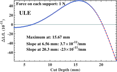
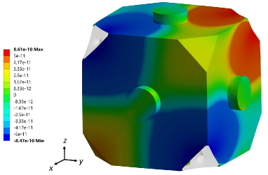
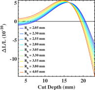
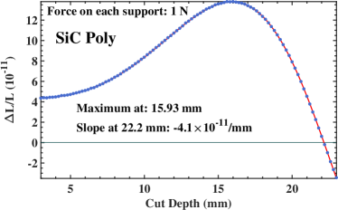
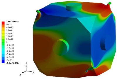
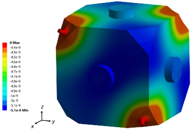
The computation was tested on a ULE cube with six mirror substrates made of ULE. The substrates considered in Webster2011 were from fused silica; this difference is minor. The cut depth was varied in the interval between mm and mm. The fractional length change of the -cavity occuring when the holding forces are applied, is depicted in Fig. 2, top left. Initially, for small cut depths, is is negative. This means that the distance between the mirrors is reduced upon application of the forces. At a cut depth of mm it crosses zero for the first time with a slope of mm. The cube deformation for this case is seen in Fig. 2 top right. Clearly, the central part of the mirror on the -face of the cube does not have any -displacement. From symmetry, also the -face remains unaffected, and this results in . After passing the cut depth of mm, the shape of the spacer becomes octahedral. Soon after, at a cut depth of mm, is maximum and then starts to decrease with increasing cut depth. The second zero crossing is reached at a cut depth of mm with a slope of mm. Among the two zero-sensitivity cut depths, the smaller one, mm, is clearly more preferable since the slope is six times smaller and so the shape is more forgiving in case of fabrication errors.
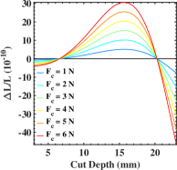
To justify our arbitrary choice of force magnitude N acting at each of the four supports, we analyzed the influence of force magnitude on optimum cut depth. We found no dependence of the position of zero-sensitivity cut depth on , when we varied the latter in the range N kN (see Fig. 2, middle left panel. Due to the large difference in scale, only simulation results for forces N are presented there). The sensitivity to force at zero crossing cut depth is /Nmm.
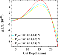
We studied the influence of unequal forces at the four supports by holding the force at a constant magnitude of N at three support points and varying the force acting at the fourth support by a factor 2. Note that this is possible without causing an overall resonator displacement since in the simulations each support surface is allowed to move only along the direction perpendicular to it. The overall effect of force variation at one support is equivalent to the application of additional longitudinal forces and generation of transversal forces at three remaining support surfaces. The results of this simulation are presented in Fig. 2, middle right panel. We found no dependence of optimal cut depth on variation of force at one support.
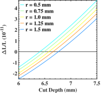
The optimum cut depth is found to increase with the size of the supports, as displayed in Fig. 2, bottom right. This could explain the small difference of mm in optimum cut depth between the result presented here and in Webster2011 . Another crucial geometry parameter that has an influence on the position of the zero crossing is the size of the cavity bores. Fig. 2, bottom left, shows that the zero sensitivity cut depth near 6.6 mm only exists if the bore radius is below mm. The second zero crossing at near mm exists for all studied bore sizes, but has a slope that increases with increasing bore size.
3.1 Influence of shape on sensitivity
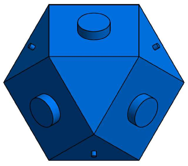
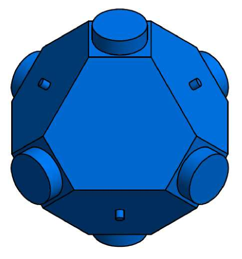
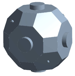
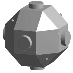
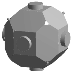
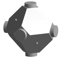
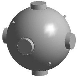
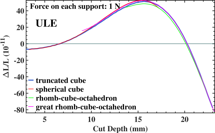
To study the influence of the resonator’s shape on the sensitivity to the support forces we studied other cavity block shapes with octahedral symmetry, such as the great rhomb-cube-octahedron Cromwell2008 , the rhomb-cube-octahedron Cromwell2008 and the spherically shaped cube (see Fig. 3). All these bodies can be produced from the cube-shaped resonator by cutting out parts of the block in a symmetric way. The distance between the mirrors was kept at mm for all shapes. Analogous to the truncated cube geometry already discussed, the supports were set in tetrahedral configuration and a force of N applied on each. The cut depth was varied equally for all of them, within the limitations of the respective geometry. The results are presented in Fig. 4. The zero-sensitivity cut depths are the same for all geometries, with the only difference being the corresponding limitations in cut depth. These results suggest that the dominant features depend only on the bulk properties of the material.
4 Cubic cavities made from conventional optical materials
Nexcera, SiC and Zerodur are well-known materials used for manufacturing optical components, in particular mirror substrates. Near room temperature Nexcera and Zerodur exhibit a zero thermal expansion coefficient . In contrast, for the material SiC it is finite, but comparatively small RohmAndHaas2008 . Tab. 1 summarizes relevant physical properties of the materials. It is well-known that a high specific stiffness leads to low cavity acceleration sensitivities. This is the reason for including SiC in the present analysis. Also listed in the table is the Poisson ratio , defined as the negative ratio of transverse strain to longitudinal strain. Thus, Poisson’s ratio is responsible for the redistribution of strain in the directions normal to the direction of the applied force.
4.1 Support force sensitivity
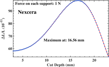
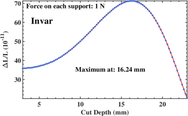
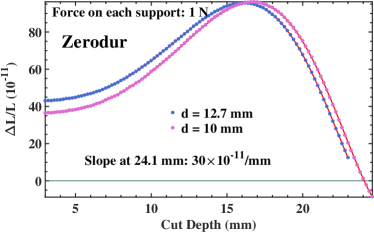
Our simulations show that for Nexcera, Invar and Zerodur, there does not exist an optimal cut depth (see Fig. 5). However, the sensitivity of Zerodur is low at high cut depth. To increase the latter we reduced the diameter of the mirrors from half-inch to mm. This results in a zero crossing of the fractional length change at a cut depth of mm, with a slope of /mm.
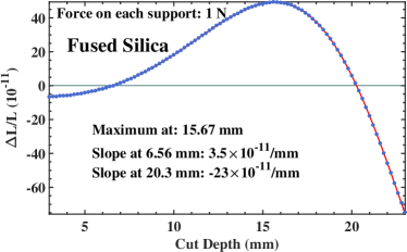
ULE is a modification of fused silica. Therefore, the fused silica resonator has zero sensitivity to at essentially the same cut depth as the ULE resonator, but with a reduced slope because of its slightly higher Young’s modulus.
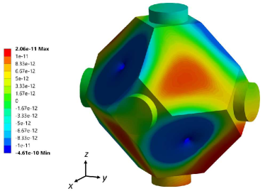
Polycrystalline -SiC has zero sensitivity at a cut depth of mm and a slope which is comparable with ULE at 6.6 mm, due to the much larger Young’s modulus. Fig. 5, bottom right shows the deformation of the -SiC block having the zero-sensitivity geometry.
The overall (”peak-peak”) variation of support force sensitivity over the complete range of cut depths is inversely proportional to the Young’s modulus. It is largest for ULE () and lowest for -SiC (). Fractional length change at a mm cut depth is the highest for Nexcera, followed in decreasing order by Zerodur, Invar, polycrystalline -SiC and the ULE (for which it is zero). With exception of Zerodur and Invar, that switch places, this sequence corresponds with the Poisson’s ratio value.
| Material | [g/] | [GPa] | [] | [] | |
| ULE Corning2008 | 2.21 | 67.6 | 0.17 | 30.59 | 00.03 |
| Nexcera KrosakiHarima2017 | 2.58 | 140 | 0.31 | 54.26 | 0.05 |
| Zerodur Schott2013 | 2.53 | 90.3 | 0.24 | 35.69 | 00.1 |
| -SiC, polycrystalline RohmAndHaas2008 | 3.21 | 466 | 0.21 | 145.2 | 2.2 |
| Fused Silica Schott2013 | 2.2 | 70.2 | 0.17 | 31.9 | 0.5 |
| Invar IVPV2017 | 8.05 | 141 | 0.259 | 17.52 | 1.0 |
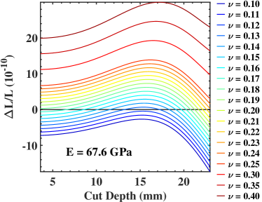
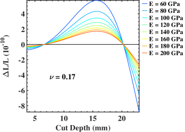
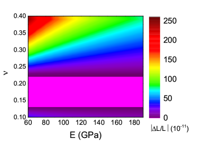
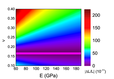
To confirm this observation, we assumed a hypothetical material and varied either the Poisson ratio or the Young’s modulus. The result is shown in Fig. 6. We find that both the Young’s modulus and the Poisson’s ratio are critical parameters. As expected, the deformation and the Young’s modulus are inversely proportional to each other. Thus, a low Young’s modulus leads to high deformation of the spacer and to high sensitivity to holding forces. On the other hand, a high Young’s modulus reduces the deformation and thus the sensitivity. A small Poisson’s ratio leads to an overall compression of a spacer, whereas a high Poisson’s ratio effectively redistributes the strain and leads to an overall expansion of the spacer. Thus, comparing the sensitivities of two different materials we can generally determine the material with higher sensitivity by comparing solely their Poisson’s ratio values. If these materials have comparable values of Poisson’s ratio, the Young’s modulus must also be taken into account. Substantial difference in Young’s modulus can change the sequence of the sensitivities based on the Poisson’s ratio. This is the case for Invar and Zerodur, where Invar is the material with higher Poisson’s ratio value (see Tab. 1) but lower sensitivity (see Fig. 5). In order to have a cut depth with zero sensitivity, the hypothetical material with the Young’s modulus between GPa and GPa must have the Poisson’s ratio within a “magic” range (Fig. 7, left). This range is reduced to for the cut depths between mm and mm (Fig. 7, right).
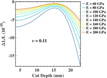
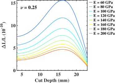
Note that the density of the material does not play a role in this consideration. This leaves ULE, fused silica, and polycrystalline -SiC as the only suitable materials among the considered isotropic ones.
4.2 Acceleration sensitivity
The results presented in the previous sections were computed in the absence of gravity and of acceleration acting at the resonator. Equal forces acting at each of the four tetrahedrically oriented supports on the block with octahedral symmetry, and pointing towards the center of the block, preserve the symmetry of arrangement.
When we include static gravity, which acts as a body force, i.e. on each volume element of the resonator, the resulting deformation lowers the resonator’s symmetry. Depending on the magnitude of the deformation, this could make necessary an adjustment of the zero-sensitivity cut depths obtained in the previous sections.
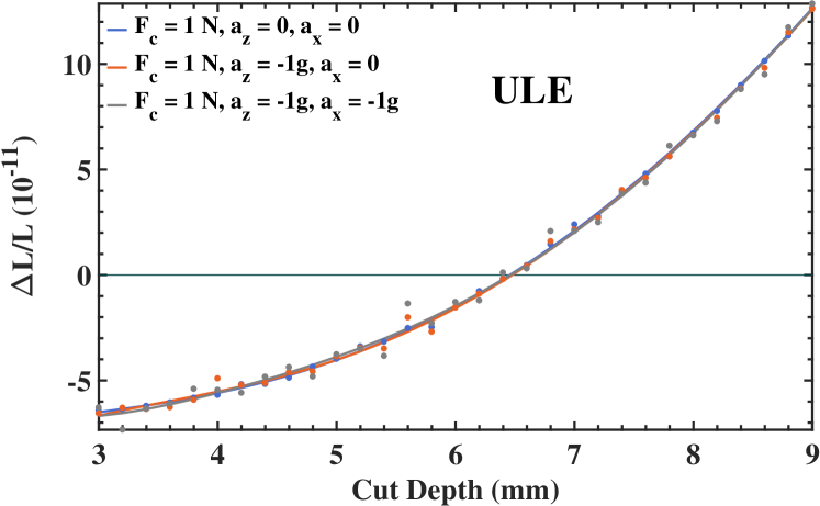
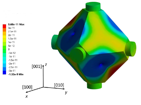
We computed the effects of acceleration on the cubic ULE resonator having 6.6 mm cut depth. The resonator was fixed in space by the supports, a force N applied to each support, and was additionally subjected to a acceleration perpendicular or parallel to the -axis (see Fig. 8). For the acceleration along the -axis, the displacements of the mirrors’ center points along the -axis are zero, see top left panel in the figure. In contrast, the -acceleration along the -axis generates displacements of both mirrors on the nm scale ( m), but equal ones, thus leaving the distance between the mirrors unchanged (see top right panel in the figure). The cancellation represents the numerical proof of the concept of Webster and Gill, which is based on the octahedral symmetry. Further simulations showed that the above displacements decrease with increasing Young’s modulus, as expected.
We have performed similar simulations for various cut depths. The results are summarized in Fig. 8. It can be seen that for the different sets of applied forces, the results are nearly equal. In particular, the optimal cut depth is not modified in the presence of gravity. We conclude that accelerations on the order of do not deform the resonator strongly enough to lower its symmetry so as to destroy the force insensitivity at the optimal cut depth determined assuming zero acceleration. We obtain the same results when the acceleration is increased by a factor 100.
5 Anisotropic materials
Additional candidate materials for a force-insensitive cubic cavity might be found among anisotropic materials, where and depend on the crystallographic direction. Silicon and sapphire are two crystalline materials of this kind, and they have already been used successfully for cryogenic optical resonators.
For an anisotropic material the relation between the applied stress and the resulting strain is Nye1964 ; Wortman1965 :
| (1) |
where and are second-rank tensors with 9 elements each and is the fourth-rank stiffness tensor with 81 elements. For crystals with cubic symmetry (e.g., silicon) both and tensors contain only six independent elements. Using a simplified Voigt notation the tensor can be reduced to the 66 symmetric matrix with only three independent elements in the Cartesian coordinate system spanned by the , , and unit vectors pointing along [100], [010], and [001] crystallographic directions. The three independent elements are denoted by , , and Hopcroft2010 :
| (2) |
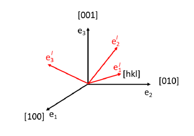
To transform to the stiffness matrix for any other Cartesian coordinate system, specified by the vectors , , and , we first lay along a particular crystallographic direction defined by the Miller indices [hkl]. The two vectors and then necessarily lie in the crystallographic plane (hkl), at right angles to each other. The transformation of is done using the algorithm described in Zhang2014 . The Young’s modulus and the Poisson’s ratio can be extracted from the compliance matrix , the inverse of the stiffness matrix , as follows Zhang2014 :
| (3) |
| (4) |
with and , where and denote the three orthogonal directions in the new coordinate system. Thus, and (, ) are the Young’s moduli along the axis and perpendicular to it, respectively. (, ) and are the Poisson’s ratios for the directions along the axis and perpendicular to it, respectively.
5.1 Silicon
Silicon is an anisotropic material which enjoys increasing popularity as a material for cryogenic optical resonators Zhang2017 ; Parker2014 ; Millo2014 ; Matei2017 ; Kessler2012a ; Hagemann2014 due to the high thermal conductivity Glassbrenner1964 , the ultra-low expansion coefficient at cryogenic temperatures Lyon1977 ; Richard1991 ; Wiens2014 ; Wiens2015 and the ultra-low length drift Hagemann2014 ; Wiens2016 . Three independent elements of the stiffness matrix from eq. (2) are GPa Mason1958 .
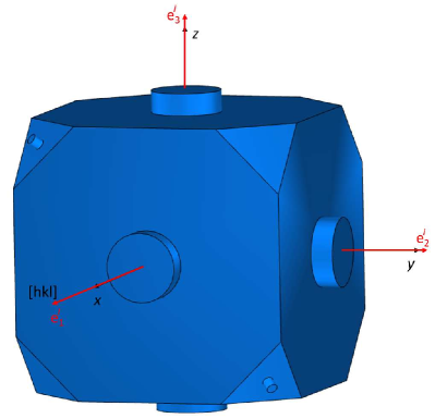
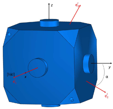
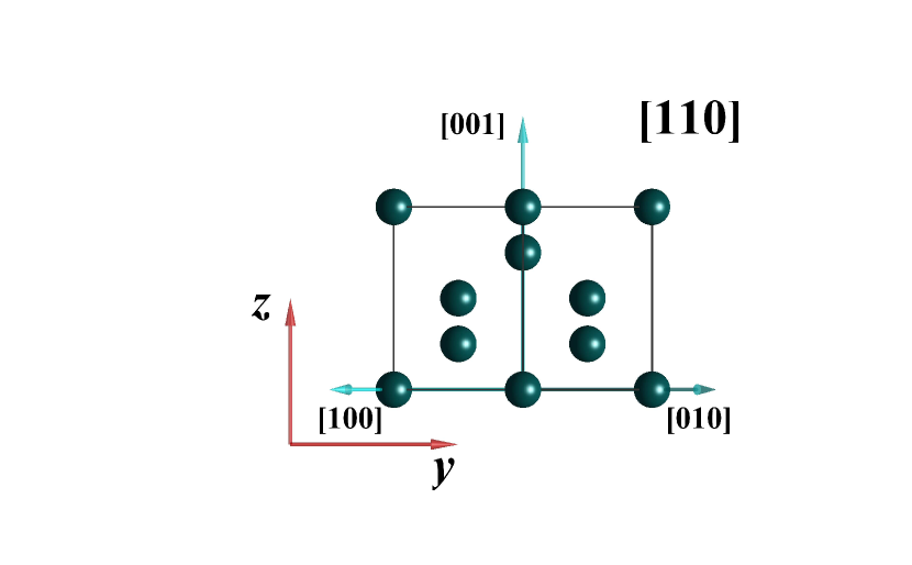
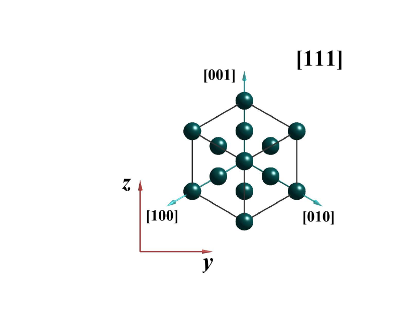
In order to set up the simulation for any desired crystallographic direction [hkl], we first orient the resonator with the optical axes of the three cavities laying parallel to the coordinate axes of the fixed laboratory reference frame, as shown in Fig. 9, top left panel. Then, we define the new coordinate system by pointing along the [hkl] crystallographic direction and by defining the two vectors and in the crystallographic plane (hkl), at right angles to each other (see Fig. 9, top right panel). Because of the cubic symmetry of the silicon lattice, we only need to consider crystallographic directions that lie inside the unit stereographic triangle whose corners are defined by the [100], [110], and [111] directions. In the next step, we orient the crystal structure with the chosen crystallographic direction [hkl] along the axis of the cube. Two other unit vectors and are laid along the and axes, respectively (see Fig. 9, bottom left panel). To find all possible orientations of interest we can introduce an additional degree of freedom by rotating the crystal counterclockwise around the [hkl] direction, as seen along the x-axis (see Fig. 9, bottom right panel). This is done first by rotating the vectors and in the crystallographic plane (hkl) by an angle around the axis using Rodrigues’ rotation formula Battin1999 (see Fig. 9, bottom right panel). After rotation, the algorithm from Zhang2014 is applied again to obtain the stiffness matrix , the Poisson’s ratio and , and the Young’s modulus and . This procedure is repeated for different values of until one full circle of rotation is completed. We note, that due to rotation, we only need to consider and as the Young’s modulus and the Poisson’s ratio for the direction perpendicular to the -axis, respectively, as they contain all necessary information. The and can be ignored.
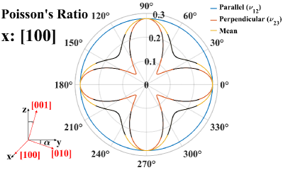
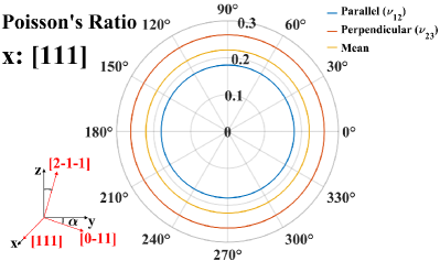
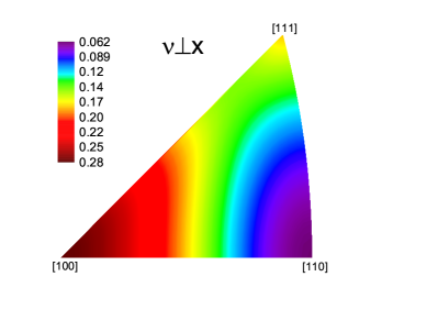
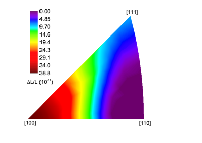
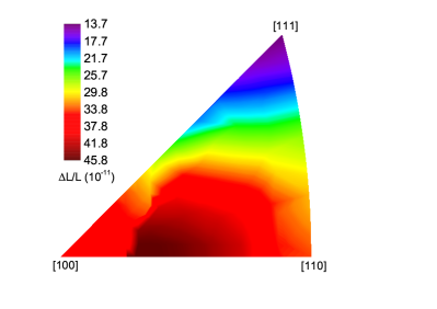
The values of for rotation around the [100], [110], and [111] characteristic directions are visualized in Fig. 10, where the values of the Poisson’s ratio that correspond to the “magic” range were colored green.
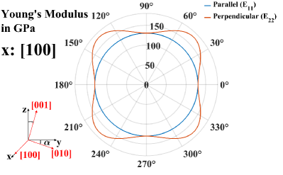
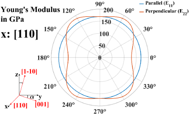
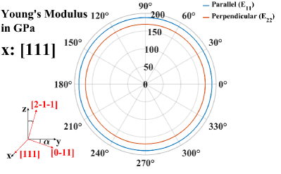
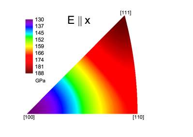
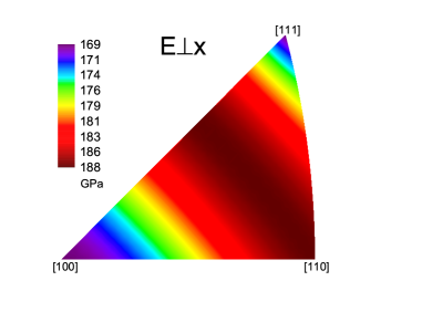
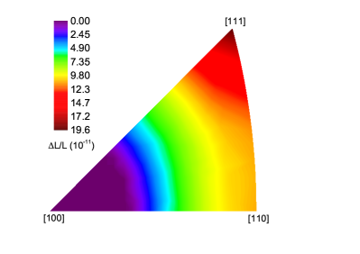
The maximum of the Young’s modulus and the minimum of the Poisson’s ratio for all angles of rotation for any given direction [hkl] inside the unit stereographic triangle are presented in Fig. 11. The Young’s modulus varies from GPa to GPa for the directions parallel to [hkl] (top, left) and from GPa to GPa for the perpendicular direction (top, right). Directions which provide the highest stiffness are the [111] and [110] directions, respectively.
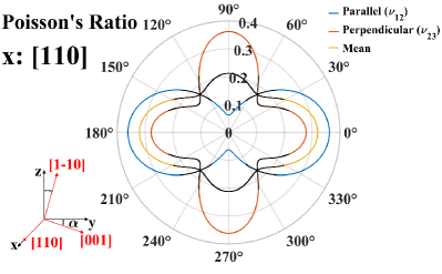
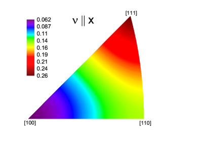
As we know from the foregoing discussion on isotropic materials, the Poisson’s ratio plays the crucial role. In order to have zero sensitivity it should lie within a “magic range” . The Poisson’s ratio varies from 0.062 to 0.26 for the parallel direction (bottom, left) with a minimum along [100] and a maximum along [111]. The variation in the perpendicular direction is from 0.062 to 0.28 with the minimum along [110] and the maximum along [100]. This large difference makes it impossible to predict which directions will have zero sensitivity and makes extensive simulations necessary.
Since the material is anisotropic, we now calculate the length changes of all three cavities within the cube, i.e. for , which may differ. We repeat the simulations for different crystallographic directions inside the unit stereographic triangle, which is oriented along the -axis.
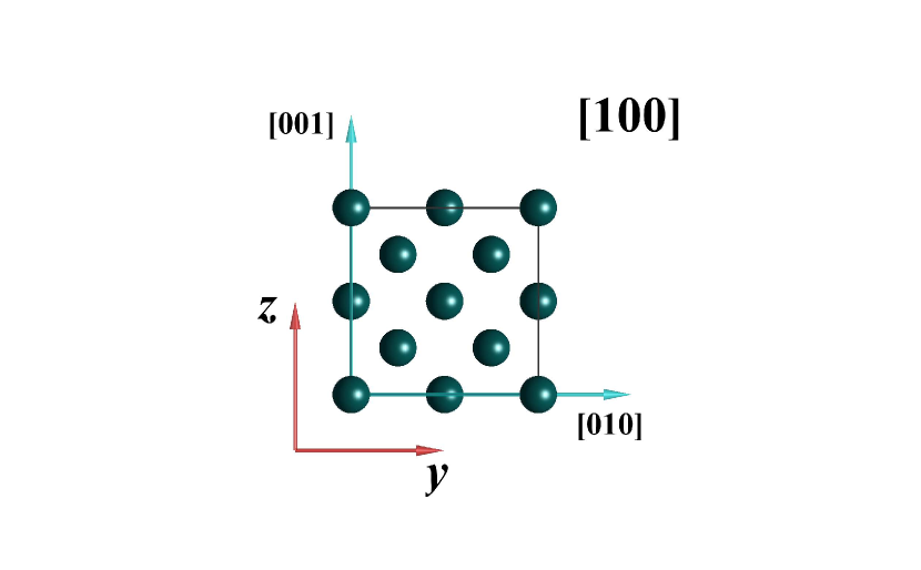
A first result of the FEA simulation is shown in Fig. 12, left column, where only the three characteristic directions [100], [110], and [111] are considered. The right column visualizes the corresponding crystal structure seen along these directions.
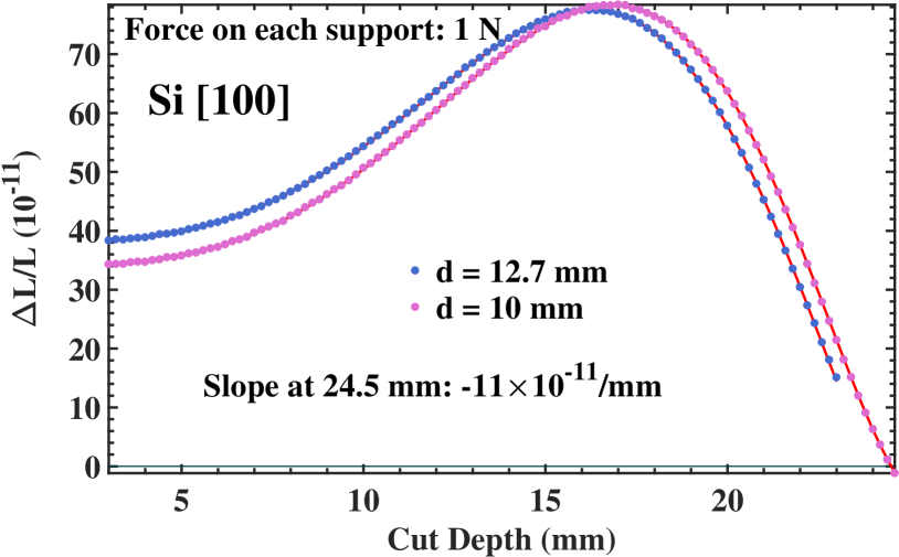
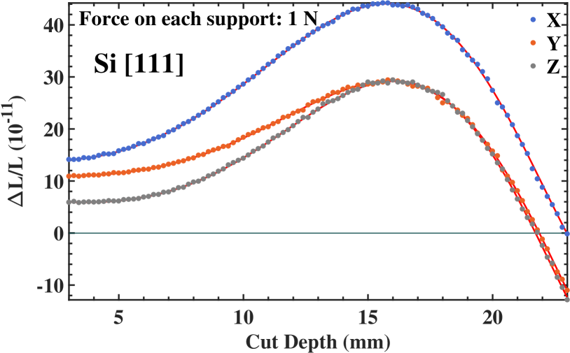
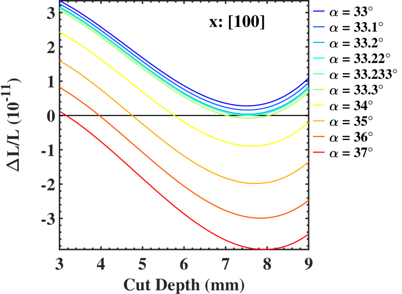
The [100] direction (top left panel) is the only one, for which all three cavities exhibit equal sensitivity to the holding force. For this direction, the FEA is performed directly with , eq. (2). However, no zero sensitivity is possible with the half-inch mirror substrates (blue points). Reduction of the mirror diameter to mm (magenta points) allows achieving a zero sensitivity for all three cavities simultaneously at a cut depth of mm with a slope of /mm. The corresponding simulation results are depicted in more detail in Fig. 13. We designate this geometry as Si-I.
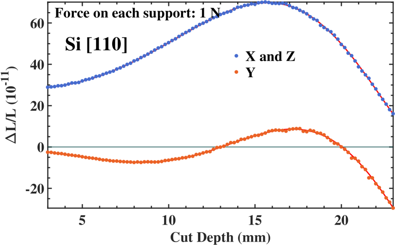
The [110] direction (middle left panel) displays identical sensitivity for two cavities but without zero sensitivity cut depth. The third cavity, the -cavity, has zero sensitivity for two appropriate cut depths (see Fig. 12, middle left panel). The slopes at mm and at mm cut depth are /mm and /mm, respectively. They are smaller than for the ULE case.
The [111] direction (bottom left panel) has different sensitivities for all three cavities (see Fig. 12, bottom left panel). They all have zero sensitivity at large cut depths. The difference in optimum cut depth for the - and -cavities is particularly low, mm. This value is comparable with the typical manufacturing precision of mm. Thus, the [111] orientation makes it possible to access two orthogonal cavities having small sensitivities. If the cut depth is chosen such that the sensitivity of one cavity is zero, the sensitivity of the second cavity is then approximately /mm.
The foregoing discussion makes it clear that there must be multiple orientations inside the unit triangle which yield zero sensitivity for at least one cavity. However, we are only interested in orientations which have the effective Young’s modulus along the [hkl] direction and perpendicular to it as high as possible, in order to relax the requirement on the manufacturing precision of the vertices’ cut depth. The effective Poisson’s ratio for these directions must be in the range which allows the cavities to have zero sensitivity. To identify these directions an extensive simulation was carried out, which is described in the next section.
5.2 Simulation procedure
We performed simulations for more than 100 different directions inside the unit triangle. The stiffness matrix for each direction was input into the simulation software. The chosen crystallographic direction was oriented along the -axis of the laboratory reference frame. This orientation together with the stiffness matrix defines the orientation of the crystal along the - and -axes. Then the crystal was turned in 10 degree steps around the -axis of the laboratory reference frame. (see Fig. 9). At each angle the force 1 N was applied at each of the supports and pointing to the center of the cube, and the deformations of the three cavities along their axes calculated.
The cut depth of the resonator was held constant at one particular value, since it would have been too time-consuming to vary this parameter as well. Its value was chosen based on the foregoing discussion, which made clear that the slope of sensitivity is lower when the resonator has the shape of a truncated cube. At a cut depth of mm the shape of the resonator changes to a truncated octahedron, which always has a higher sensitivity slope. For that reason, the cut depth was fixed near the mean of the values corresponding to a truncated cube, mm.
5.3 The support force sensitivity
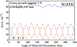
The results for the three corner directions of the unity triangle, [100], [110], [111], are presented in Fig. 14. As the top right panel shows, the fractional length changes of the three cavities are equal only for the [100] crystallographic direction and rotational angle. For all other orientations and angles (all panels), at least two of the three cavities display different fractional length changes. This is due to the differences in the lattice structure along the cavity axes. The -cavity of the [100] orientation crosses zero fractional length change twice in the angle interval between 0 and 90 degrees. Two other cavities have an equal sensitivity at all angles with a minimum of . The cube with the [110] material orientation (bottom left panel) has zero sensitivity crossings for the - and -cavities and no crossing for the -cavity. All cavities of the resonator with the [111] orientation (bottom right panel in the figure) have no zero sensitivity.
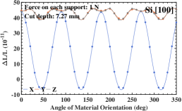
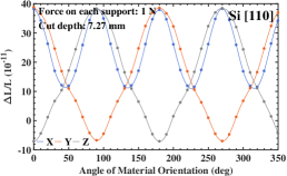
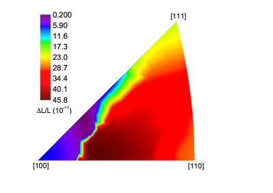
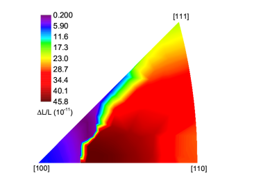
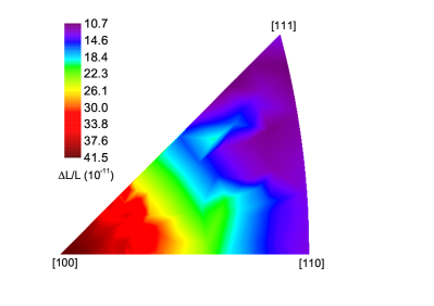
The minimum fractional length changes ocurring over a full turn around all orientations ( varies between 0 and deg.) inside the unity triangle are displayed in Fig. 15. As we can see, there is only one favorable orientation for each cavity, shown in purple (top row). To have zero sensitivity for the -cavity the resonator must be oriented along the [100] direction, see top left panel. Zero sensitivity for the - and -cavities is only possible if resonator is oriented along the [110] direction, but not at the same angle. As Fig. 14, bottom left panel, suggests, there is an angle shift of 90 degrees between them. Our results rule out the possibility of having zero sensitivity for more then one cavity simultaneously, for the considered vertex cut depth. In Fig. 15 we display sensitivities along the two axes at an angle of minimum sensitivity for the one of the three axis. As in the case of isotropic materials we compare our results with the Poisson’s ratio (see Fig. 11 and Fig. 15). Both the -cavity sensitivity and the Poisson’s ratio have a minimum in the vicinity of the [100] direction. The minimum of the sensitivity for the - and -cavities and for [110] silicon orientation (see Fig. 15, top right panel) corresponds to the minimum of the Poisson’s ratio calculated for the direction perpendicular to [110] (see Fig. 11, bottom right panel).
The evaluation of the Young’s modulus for the direction parallel to the crystallographic orientation and perpendicular to it is presented in Fig. 15, top row panels. For example, we find that the direction [110], with the Young’s modulus of GPa along the -axis and GPa perpendicular to it, is more favorable than the [100] direction, for which the values are GPa and GPa, respectively.
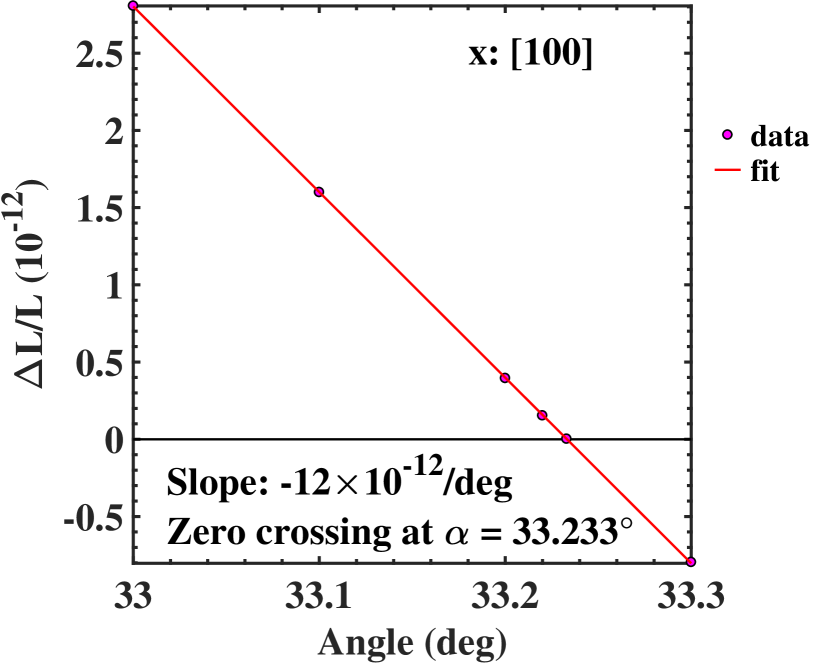
This difference should be reflected in the dependence of the fractional length change on the variation in cut depth and in angle of rotation around their optimal values. To obtain these numbers we performed a series of simulations displayed in Fig. 16. We find that for the [100] orientation (top row) both and its sensitivity to cut depth variation are zero at a cut depth of 7.54 mm and at angle degree. This case is denoted by Si-II in the following. The fractional length change varies by /deg around the optimum angle and by /mm around the optimum cut depth.
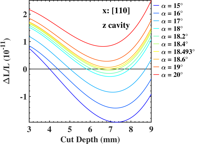
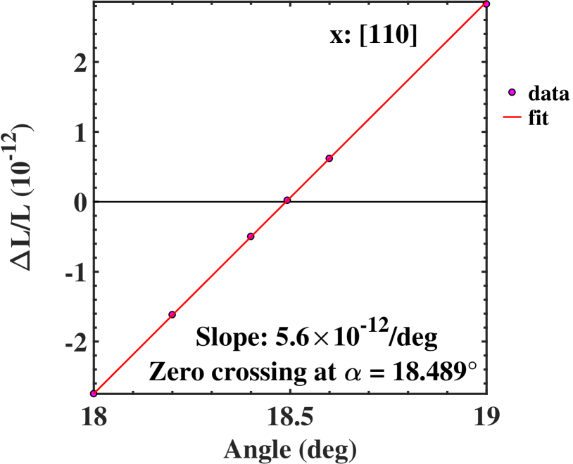
The bottom row of panels shows that the cube with [110] orientation has a zero sensitivity of the -cavity at an angle of 18.49 degree and at a cut depth of 6.88 mm (geometry denoted by Si-III). The -cavity displays a zero crossing at the same cut depth but at an angle which is shifted by degrees from that of the -cavity (see Fig. 14, bottom left panel) The fractional sensitivity variations are /deg and /mm for the variations in angle and cut depth, respectively.
6 Effect of imperfections
We evaluated the effect of additional imperfections on the sensitivity to the supporting force and on the acceleration insensitivity, besides the already considered cut depth deviation and orientation deviation (for anisotropic materials). For silicon we consider only the geometries Si-I, Si-II, Si-III introduced above, and for ULE and -SiC the shapes of Sec. 4. The results are presented in Table 2. Item 1 in the table reports results already discussed above.
The cut depth of the individual resonator vertices may vary due to the accuracy of manufacture. We analyze the case that only one vertex (also serving as support) deviates in cut depth from the other seven. Tab. 2, item 2, shows that for a cut depth precision of 0.1 mm, the cavity length deformation effects are at the level of per N support force or smaller. In the gravity field this imperfection introduces an acceleration sensitivity Max on the order of or smaller.
Misplacement of the mirrors with respect to the symmetry axes of the cube can occur during assembly. As a result, the light propagation occurs along an axis shifted with respect to the symmetry axis. This breaks the symmetry assumed in the concept of the cubic block. Different deformation of the opposing mirrors at the intersection of the axis and the mirror surface introduces an additional length change and degrades the acceleration sensitivities . The calculation of the degradation was performed for a mm shift of the optical axis in the direction having the largest deformation. The value 1 mm is larger than errors in fabrication and only serves as an example. Our result for ULE, given in the table (item 3), appears consistent with the FEA value reported by Webster2011 . For silicon, we find acceleration sensitivities up to .
The sensitivity to orientation of the Si crystal with respect to the resonator is reported under item 4; we find the acceleration sensitivities to be rather small if an error of 1 degree is assumed.
Asymmetrical mounting of the resonator in the frame with the supports displaced from their optimal position is another source of error (items 5, 6 in the table). We see that the effects are not negligible. For an offset of mm, in the case of ULE the cavity length changes fractionally by for a 1 N support force, and a sensitivity to acceleration perpendicular to the cavity arises. For silicon the numbers are similar.
The above results make it clear that great care should be taken in mounting the resonator in the supporting frame. Together with the offsets of mirrors from the respective symmetry axes, mounting errors appear to be a major potential cause of the degradation of sensitivity compared to the ideal. Comparing silicon with ULE we find that silicon is less sensitive to errors, but in several respects only by a factor approximately 2. Comparing the three silicon resonator geometries, Si-I, Si-II, and Si-III, we find Si-II to be more advantageous, in particular with respect to one critical error, the offset from the optical axis.
| Type of geometry change | Quantity | Material and orientation | ||||
| ULE | -SiC | Si-I | Si-II | Si-III | ||
| 1. Cut depth, all vertices | ||||||
| 0 | 0 | 0 | 0 | 0 | ||
| 2. Cut depth, one vertex | ||||||
| , | , | , | , | , | ||
| 3. Offset of the optical axis | ||||||
| , | , | , | , | , | ||
| 4. Orientation of material | - | - | ||||
| - | - | , | , | , | ||
| 5. Horizontal offset of one support | ||||||
| , | , | , | , | , | ||
| 6. Vertical offset of one support | ||||||
| , | , | , | , | , | ||
7 Error evaluation
To determine the influence of finite mesh size on the optimum cut depth we performed simulations of a ULE block applying different mesh density. Assuming that simulations with infinitely small mesh size adequately represent the reality, we extrapolated our results toward decreasing mesh size and obtained an error of less then mm for the optimum cut depth.
We also evaluated the scatter of data points in different simulation results by fitting them with a polynomial of high degree and plotting the distribution of the residuals. This evaluation indicates an error in sensitivity of for the simulations where no acceleration is involved and an error of whenever an acceleration is applied. This error was found to have approximately cubic dependence on mesh size.
Another way to validate our simulation procedures is to compare with published results. In Matei2016 , a vertically oriented, biconical silicon resonator was simulated and the results experimentally validated. Our simulations are in good agreement.
8 Summary and conclusion
We analyzed the sensitivity to support forces of the three-cavity cubic block made of different materials. For isotropic materials, we identified a “magic” range for Poisson’s ratio, , for which the three cavity lengths become insensitive to the strength of the support force. Because of this particular range, apart from ULE, only fused silica and -SiC are suitable materials among the common isotropic materials used in the optics industry. Silicon, as anisotropic material, offers multiple suitable orientations for providing zero sensitivity. Based on FEA simulations, we identified two orientations, [100] and [110], to be particularly suitable. Compared to ULE, they provide one cavity with more robustness to the errors in manufacturing: the acceleration sensitivity is reduced by a factor of approximately or more compared to ULE, depending on the error.
We thus showed that silicon spacers with octahedral symmetry can provide a favorable option for cryogenic, support-force-insensitive and vibration-insensitive cavities. Particularly attractive is the fact that there exists one geometry, with [100] orientation of the crystal, which provides simultaneously three nominally insensitive cavities in the same spacer. This geometry could be useful for certain applications, e.g. tests of Lorentz Invariance. Nevertheless, even with only 0.1 mm imprecision in manufacturing and mounting, a residual sensitivity to support force at the level of level can occur. The corresponding residual vibrational sensitivity can be as high as . Achieving a suitable design and production of the frame that provides stable support forces will be an important additional aspect of the overall system.
Acknowledgements.
We thank T. Legero (PTB) for providing us with the design of the biconical Si resonator allowing us to test our simulations, A. Nevsky for stimulating discussions, and D. Sutyrin for his help with the simulations. This work was performed in the framework of project SCHI 431/21-1 of the Deutsche Forschungsgemeinschaft.References
- (1) N. Huntemann, C. Sanner, B. Lipphardt, C. Tamm, E. Peik, Phys. Rev. Lett. 116(6), 063001 (2016)
- (2) A.D. Ludlow, M.M. Boyd, J. Ye, E. Peik, P.O. Schmidt, Rev. Mod. Phys. 87, 637 (2015)
- (3) T. Nicholson, S. Campbell, R. Hutson, G. Marti, B. Bloom, R. McNally, W. Zhang, M. Barrett, M. Safronova, W. Strouse, G.F. Tew, J. Ye, Nat. Commun. 6, 6896 (2015)
- (4) P. Antonini, M. Okhapkin, E. Göklü, S. Schiller, Phys. Rev. A 71, 050101(R) (2005)
- (5) C. Eisele, A.Y. Nevsky, S. Schiller, Phys. Rev. Lett. 103, 090401 (2009)
- (6) E. Wiens, A.Y. Nevsky, S. Schiller, Phys. Rev. Lett. 117, 271102 (2016)
- (7) S. Webster, P. Gill, Opt. Lett. 36(18), 3572 (2011)
- (8) K. Numata, A. Kemery, J. Camp, Phys. Rev. Lett. 93(25), 250602 (2004)
- (9) M. Notcutt, L.S. Ma, A.D. Ludlow, S.M. Foreman, J. Ye, J.L. Hall, Phys. Rev. A 73(3), 031804 (2006)
- (10) J. Davila-Rodriguez, F.N. Baynes, A.D. Ludlow, T.M. Fortier, H. Leopardi, S.A. Diddams, F. Quinlan, Opt. Lett. 42(7), 1277 (2017)
- (11) S. Seel, R. Storz, G. Ruoso, J. Mlynek, S. Schiller, Phys. Rev. Lett. 78, 4741 (1997)
- (12) D.G. Matei, T. Legero, S. Häfner, C. Grebing, R. Weyrich, W. Zhang, L. Sonderhouse, J.M. Robinson, J. Ye, F. Riehle, U. Sterr, Phys. Rev. Lett. 118, 263202 (2017)
- (13) W. Zhang, J.M. Robinson, L. Sonderhouse, E. Oelker, C. Benko, J.L. Hall, T. Legero, D.G. Matei, F. Riehle, U. Sterr, J. Ye, Phys. Rev. Lett. 119(24), 243601 (2017)
- (14) E. Wiens, Q. Chen, I. Ernsting, H. Luckmann, A.Y. Nevsky, U. Rosowski, S. Schiller, Opt. Lett. 39, 3242 (2014)
- (15) E. Wiens, Q. Chen, I. Ernsting, H. Luckmann, A.Y. Nevsky, U. Rosowski, S. Schiller, Opt. Lett. 40, 68 (2015)
- (16) C. Hagemann, C. Grebing, C. Lisdat, S. Falke, T. Legero, U. Sterr, F. Riehle, M.J. Martin, J. Ye, Opt. Lett. 39, 5102 (2014)
- (17) P.R. Cromwell, Polyhedra (Cambridge University Press, Cambridge, UK, 2008)
- (18) Product sheet from Rohm and Haas Co. URL http://www.dow.com/
- (19) Product sheet from Corning, Inc. URL https://www.corning.com
- (20) N118C Product sheet from Krosaki Harima. URL https://krosaki-fc.com/en/ceramics/nexcera.html
- (21) Product sheet from SCHOTT North America, Inc. URL http://www.us.schott.com/english/index.html
- (22) M. Bass, Handbook of Optics, 2nd edn. (McGraw-Hill, 1995)
- (23) J.F. Nye, Physical Properties of Crystals: Their Representation by Tensors and Matrices (Oxford: At the Clarendon Press, Oxford, U.K., 1964)
- (24) J.J. Wortman, R.A. Evans, J. Appl. Phys. 36(1), 153 (1965)
- (25) M.A. Hopcroft, W.D. Nix, T.W. Kenny, J. Microelectromech. S. 19(2), 229 (2010)
- (26) L. Zhang, R. Barrett, P. Cloetens, C. Detlefs, M. Sanchez del Rio, J. Synchrotron Radiat. 21(Pt 3), 507 (2014)
- (27) R.H. Battin, An introduction to the mathematics and methods of astrodynamics, rev. ed. edn. AIAA Education Series (American Institute of Aeronautics and Astronautics, Inc., Reston, Virginia, 1999)
- (28) B. Parker, G. Marra, L.A.M. Johnson, H.S. Margolis, S.A. Webster, L. Wright, S.N. Lea, P. Gill, P. Bayvel, Appl. Opt. 53(35), 8157 (2014)
- (29) J. Millo, C. Lacroute, A. Didier, E. Rubiola, Y. Kersalé, J. Paris, in 2014 European Frequency and Time Forum (EFTF), 531 (2014)
- (30) T. Kessler, C. Hagemann, C. Grebing, T. Legero, U. Sterr, F. Riehle, M.J. Martin, L. Chen, J. Ye, Nat. Photonics 6, 687 (2012)
- (31) C.J. Glassbrenner, G.A. Slack, Phys. Rev. 134(4A), A1058 (1964)
- (32) K.G. Lyon, G.L. Salinger, C.A. Swenson, G.K. White, J. Appl. Phys. 48(3), 865 (1977)
- (33) J.P. Richard, J.J. Hamilton, Rev. Sci. Instrum. 62, 2375 (1991)
- (34) W.P. Mason, Physical Acoustics and the Properties of Solids (Van Nostrand, Princeton, N.J., 1958)
- (35) D.G. Matei, T. Legero, Ch. Grebing, S. Häfner, Ch. Lisdat, R. Weyrich, W. Zhang, L. Sonderhouse, J. M. Robinson, F. Riehle, J. Phys.: Conference Series 723(1), 012031 (2016)