Attractive interaction between superconducting vortices in tilted magnetic fields
Abstract
Many practical applications of high Tc superconductors involve layered materials and magnetic fields applied on an arbitrary direction with respect to the layers. When the anisotropy is very large, Cooper pair currents can circulate either within or perpendicular to the layers. Thus, tilted magnetic fields lead to intertwined lattices of Josephson and Abrikosov vortices, with quantized circulation across and within layers, respectively. Transport in such intertwined lattices has been studied in detail, but direct observation and manipulation of vortices remains challenging. Here we present magnetic force microscopy experiments in tilted magnetic fields in the extremely quasi-two dimensional superconductor . We trigger Abrikosov vortex motion in between Josephson vortices, and find that Josephson vortices in different layers can be brought on top of each other. Our measurements suggest that intertwined lattices in tilted magnetic fields can be intrinsically easy to manipulate thanks to the mutual interaction between Abrikosov and Josephson vortices.
I Introduction
Strongly anisotropic layered superconductors hold Josephson vortices across layers in parallel magnetic fields Koshelev1999 . Josephson vortices have no core, because the phase winding occurs in the non-superconducting region between the layers. When the magnetic field is applied perpendicular to the layers, Abrikosov vortices with a core nucleate within each layer. Abrikosov vortices in layered superconductors are composed by columns of disk-like pancake vortices and their shear modulus is significantly smaller than the shear modulus of Abrikosov vortices in isotropic superconductors. In the absence of Josephson vortices or pinning the pancake vortices form straight lines along the -axis. But in tilted magnetic fields, there is a finite in-plane magnetic field component and Josephson vortices appear. The mutual interaction between the columns of pancake vortices and the Josephson vortices leads to deformed combined lattices consisting of tilted vortex lines having kinks and different arrangements composed by layers with alternating pancake and Josephson vortices Grigorenko01 ; Curran2018 . In Ref.PhysRevLett.88.147002 it has been shown that the pancake vortices in such composite vortex lattices in tilted magnetic fields attract each other at large distances when located on top of a Josephson vortex. This long range attraction shapes the structure of combined lattices and leads to the formation of chains of pancake vortices along Josephson vortices. The chains decorate Josephson vortices, because pancake vortices sit rather close to each other along the lines of Josephson vortices. This occurs even at small perpendicular magnetic fields.
The vortex attraction in tilted magnetic fields is quite a general phenomenon and is also expected in superconductors that are not extremely anisotropic, such as YBa2Cu3O7 and 2H-NbSe2. It is caused by the current distribution produced by tilted magnetic fields when superconducting properties are anisotropic. Supercurrents then circulate on complex paths, which consist of ellipsoids whose shape depends on the tilt of the magnetic field with respect to the crystalline direction and this easily leads to the appearance of a minimum in the interaction potential between vortices Buzdin90 ; BuzdinSimonov91 ; Grishin90 ; Grishin92 ; PhysRevLett.69.2138 ; PhysRevLett.68.3343 ; PhysRevB.46.8425 ; PhysRevB.96.174516 .
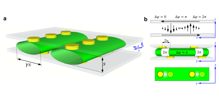
The phase diagrams with interwined Josephson and pancake lattices in highly anisotropic layered superconductors have been intensively studied as a function of the magnetic field and temperature PhysRevB.67.134501 ; PhysRevB.71.174507 ; Grigorenko01 ; Matsuda01 ; PhysRevB.66.014523 ; Koshelev1999 ; PhysRevLett.89.217003 ; Kirtley2010 ; 0953-2048-27-6-063001 ; PhysRevB.46.366 ; 0953-8984-17-35-R01 ; Zeldov2011 . Josephson vortices have circulating currents on an area defined by the interlayer separation and the in-plane length (Fig.1 a and upper panel of b). Pancake vortices have currents circulating on a disk of size of order of the in-plane penetration depth . Pancake vortices lie in each layer. Thus, there are pancake vortices in the two layers forming the Josephson vortex. The mutual interaction between the two kinds of vortices leads to a shift of the pancake vortices lying in each layer along the Josephson vortex. Thus, pancake vortices are not exactly on top of each other, as usual in an Abrikosov lattice in perpendicular fields, but are slightly displaced along the length of the Josephson vortex. This is due to the Lorentz force from the intralayer currents, which are directed opposite to each other in each layer. There is a phase change of across each vortex, once across layers for a Josephson vortex and once within each layer for a pancake vortex. But when pancake vortices are not exactly on top of each other in two adjacent layers, the phase slip across the two layers vanishes in between displaced pancake vortices. Thus there is no Josephson vortex in between two pancake vortices at two different locations on two different layers (Fig.1 b middle and bottom panels). This results in an energy gain, which is of order of the Josephson coupling energy of the section of the Josephson vortex that disappears in between pancake vortices. When repeating along the whole sample, the presence of pancake vortices on top of the Josephson vortex can thus significantly decrease the overall energy cost of tilted magnetic fields. The interaction between neighboring pancake vortices in the same layer provides a balance and there is an equilibrium distance for pancake vortices along the Josephson vortex. The variation of this distance with tilt and value of the magnetic field and with temperature leads to the equilibrium phase diagrams discussed in literature Koshelev1999 ; Grigorenko01 ; 0953-8984-17-35-R01 .
Here we study slightly underdoped (BSCCO), which is a highly anisotropic superconductor consisting in bilayers separated by a distance , with , and layers in between. We find an anisotropy factor ( with and the in plane and and the out of plane penetration depths and coherence lengths respectively). We mostly study Josephson vortices with an in-plane magnetic field. We decorate the Josephson vortices by pancake vortices and work in a strongly out of equilibrium situation. We obtain vortex patterns by modifying the amount of pancake vortices on top of the Josephson vortices through repeated heating and cooling. We show that, under such out of equilibrium situation, pancake vortices can be displaced in between Josephson vortices and that Josephson vortices can be manipulated by changing the in-plane direction of the magnetic field.
II Results
II.1 Interaction between the MFM tip and pancake vortices
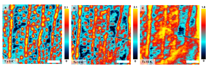
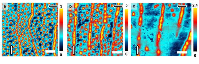
We start by discussing briefly the decoration of Josephson vortices with pancake vortices and the invasive action of the MFM tip. In Fig. 2 a we show a Magnetic Force Microscope (MFM) image of a crossing lattice of Josephson and pancake vortices obtained at 5 K. To obtain this image we first apply a magnetic field of 50 G perpendicular to the layers. This introduces pancake vortices in the sample. We then apply 200 G parallel to the layers and ramp the perpendicular component down to zero. We briefly heat the sample to above 50 K and cool down again. This leads to a re-arrangement of pancake vortices that position themselves along the Josephson vortices, creating the vertical rows shown in Fig. 2 a.
By heating above 50 K again, we can reduce the amount of pancakes in between Josephson vortices until we reach a non-equilibrium situation with an in-plane magnetic field and pancake vortices lying on top of Josephson vortices, discussed below.
It is quite convenient to discuss the invasive action of the MFM tip using the location shown in Fig. 2 a, which was obtained before repeated heating and has quite a large amount of interstitial vortices. When we increase the temperature from 5 K to 15 K (Fig. 2 b,c), we observe that the size of pancake vortices in the images is considerably increased when reaching 15 K (see also Supplementary Information). At higher temperatures, we do not resolve pancake vortices anymore. This increase in apparent size is due to thermal motion. Thermal motion is activated by the wiggling action produced by the MFM tip when scanning on pancake vortices, in a similar way that vortex lattice melting is favored by a dithering AC magnetic field. To complete a square image, the tip scans along a line (say, the x-axis, as in Fig. 2) and then moves to the next. Thus, it moves fast along one direction (say, x-axis) and slow along the other direction (say, y-axis). The tip scans several times over each pancake vortex when moving along the fast scan direction. As shown in Ref.Avraham2001 , a dithering magnetic field considerably reduces vortex pinning. It has been shown previously that scanning a magnetic tip produces such a dithering field locally and enough vortex shaking to eliminate pinning Straver2008 ; Auslaender2008 ; doi:10.1142/S0217979210056384 ; PhysRevB.80.054513 ; Embon2015 ; PhysRevB.80.054513 ; PhysRevE.87.022308 ; doi:10.1021/acs.nanolett.5b04444 . This allows to manipulate pancake vortices thanks to the dithering magnetic field produced by the tip motion during scanning. It is interesting to note that the temperature where we observe depinning, which is of 15 K, is far below the depinning temperature of BSCCO (a few K below T 88 K) Schwarz2010 ; Koshelev1999 . The depinning temperature was reduced down to about 30 K in a similar sample by dithering magnetic fields in Ref.Avraham2001 . In our experiment, we reach temperatures about half that value, suggesting that the spatial gradient of the magnetic field plays a role and increases the force on vortices during this process. By increasing and decreasing the temperature in a relatively small interval, we can thus trigger pancake vortex motion using our MFM tip.
II.2 Moving pancake vortices between Josephson vortices
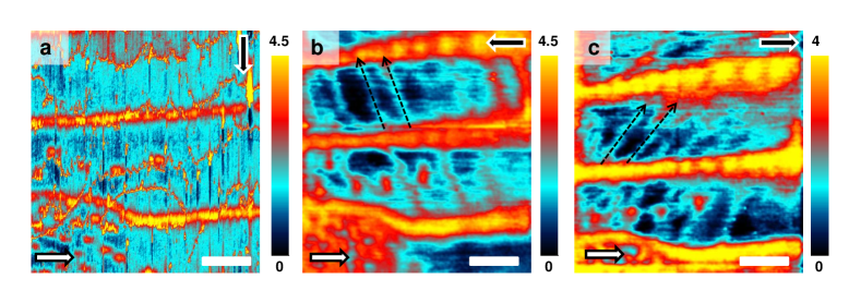
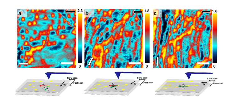
We now study a situation where we have built a decorated Josephson vortex lattice with only a few interstitial pancake vortices and show that we can move pancake vortices across Josephson vortices using the MFM tip. In the Fig. 3 a, the tilt is along the x axis of the image and most pancake vortices are aligned and pinned at the Josephson vortices. The in plane component of the magnetic field in this image is aligned with the slow axis of the scan direction. We then increase the temperature to 12 K and exchange slow and fast scanning directions. We observe the images shown in Figs. 3 b,c. Pancake vortices move across Josephson vortices. Note that vortex motion is perpendicular to the slow scan direction. This corresponds to the view that the dithering AC magnetic field reduces or eliminates vortex pinning. The fast scanning acts to reduce the pinning and the vortices are slowly pushed along the slow scan direction when the tip moves from one line to the next. Correspondingly, vortex motion is not exactly perpendicular to the Josephson vortices, but with a small angle (see also Supplementary Figure S3). The angle depends on the direction of the fast scan, from right to left (Fig. 3 b) or viceversa (Fig. 3 c).
II.3 Approaching and crossing Josephson vortices
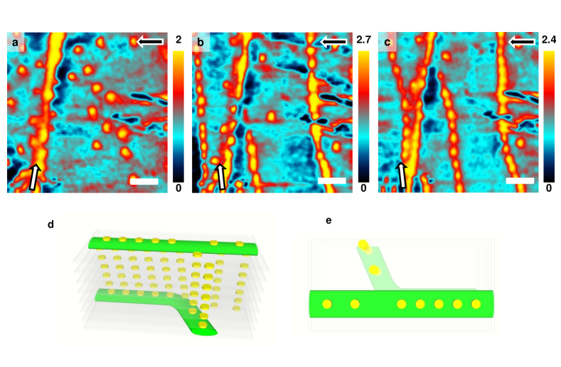
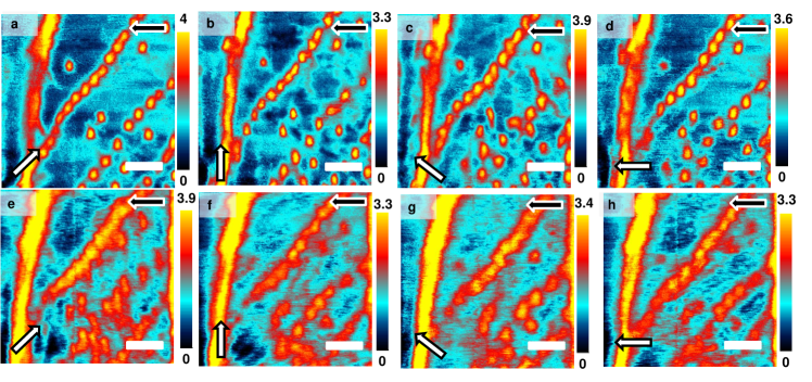
We now produce crossing Josephson vortices using the combined action of pinning and changing the direction of the in-plane magnetic field. We start by nucleating a single decorated Josephson vortex in a field of view that has a linear defect. The linear defect is actually a large circular wrinkle, shown in the Supplementary Figure 8. We apply the in-plane magnetic field exactly along the defect and observe that we nucleate a Josephson vortex along the defect (Fig. 4 a). We then turn the in-plane magnetic field by about 10 degrees and heat and cool several times. We observe further Josephson vortices in the field of view. These are Josephson vortices that are oriented along the tilt of the magnetic field and are thus at an angle with respect to the Josephson vortex pinned at the wrinkle (Fig. 4 b,c). Heating and cooling from Fig. 4 b to Fig. 4 c leads to motion of the decorated Josephson vortex lines. As we can see in the left part of the Fig. 4 c, the Josephson vortices do not repel. The leftmost Josephson vortex has approached the pinned Josephson vortex and the Josephson vortex in the middle of the image Fig. 4 c results from the motion of a Josephson vortex from the lower left corner to the middle of the image. In this process, the latter vortex has joined to pancakes that were previously located in between Josephson vortices in the middle of the image in Fig. 4 b. The observed lines of Josephson vortices, lying in different layers (as discussed below), clearly cross each other. The density of pancake vortices along the crossing Josephson vortices changes when they are close to each other. For instance, the upper part of the leftmost Josephson vortex in Fig. 4 c has a smaller density than the lower part.
III Discussion
Most previous experiments dealing with crossing Josephson and pancake vortex lattices were made close to liquid nitrogen temperatures using non-invasive imaging such as scanning Hall microscopy. Modifications in the Josephson vortex structure can then be made by changing the direction of the magnetic field Grigorenko01 ; 0953-8984-17-35-R01 .
In our experiments, we take advantage of dithering field produced by the moving MFM tip. The magnetic field due to the scanning MFM tip oscillates with a frequency of the order of several tens or hundreds of Hz (see Methods section for details). Previous experiments used the same effect to move vortices in other cuprates with less in-plane vs out-of-plane anisotropy and in thin films of low temperature superconductors Straver2008 ; Auslaender2008 ; doi:10.1142/S0217979210056384 ; PhysRevB.80.054513 . Macroscopic experiments have shown vortex shaking at frequencies ranging from tens of Hz to hundreds of kHz also in both low temperature and in cuprate superconductors, including BSCCO PhysRevB.84.012508 ; PhysRevE.87.022308 ; Avraham2001 . This provides the opportunity to manipulate vortices and show their vortex motion and mutual interaction at low temperatures, even in presence of strong pinning and interacting Josephson and pancake vortex lattices in BSCCO.
When the magnetic field is parallel to the layers, say of , the distance between Josephson vortices along the -axis nm, which is nearly an order of magnitude larger the distance between superconducting CuO2 bilayers ( 1.5 nm). The pancakes decorate two adjacent rows of Josephson vortices. These occupy different interlayer spaces, shifted by nm PhysRevB.68.094520 . Therefore, when we drag the row of pancake vortices toward the pancake vortices decorating another Josephson vortex in the experiment shown in (Fig. 4 b,c), the approach and crossing occurs between different layers. When two Josephson vortices cross (Fig.4) the rows of pancakes are additionally distorted by the flux from the pancakes in the Josephson vortex immediately below (Fig. 4 c,d). The resulting decrease of the vortex energy provides a mechanism of a short range attraction between rows of Josephson vortices.
The energy per unit area of the Josephson interaction between superconducting layers is given by , where and is the phase difference between layers PhysRevB.68.094520 . By contrast, the energy due to the mutual attraction between two pancakes to lie on top of each other is where is the displacement of pancake vortices between layers (Fig.1 b). When pancake vortices are displaced along the Josephson vortex, the total energy is of order of . The crossing of the pancake stack with a Josephson vortex produces stack’s deformation and leads to the energy decrease PhysRevB.68.094520 .
When two Josephson vortices are one under the other, the same pancake stacks cross them, which doubles the energy gain due to the crossing. This leads to the attraction between these Josephson vortices. The corresponding attractive force (per one stack crossing) can be estimated as , where we took into account that the effective mutualisation of the pancake stacks occurs when the distance between Josephson vortices is less than . The equilibrium distance between pancake stacks decorating Josephson vortex is and the attraction force (per unit length) between Josephson vortices can be estimated as Nm-1. This force is comparable to the repulsive force between Josephson vortices . This makes it possible to obtain the metastable configuration of Josephson vortices with crossing and branching as observed in the experiments and shows that Josephson vortices lying in different planes have a tendency to share pancakes.
Ref.PhysRevLett.89.217003 has extensively discussed the interaction between linear defects in the CuO2 bilayers and crossing lattices using Scanning Hall Microscopy and tilted magnetic fields at liquid nitrogen temperatures. It has been shown that pancake vortices can be preferentially pinned at linear defects, favoring that Josephson vortices are located along these lines. Usually, linear defects lie perpendicular to each other and are of a finite length. This can lead to kinks in the pancake vortex distribution when abruptly modifying the in-plane magnetic field, because some vortex sections remain pinned whereas others free themselves. Images then show Josephson vortices that fork, similar to those we see in our experiment. Experiments in PhysRevLett.89.217003 were made close to liquid nitrogen temperatures, whereas we work at much lower temperatures. Furthermore, they abruptly modified the magnetic field, whereas we use a superconducting coil which is slow. Finally, the phenomenon of forking appears here in a strong linear defect. This is a true wrinkle that leads to a considerable modification of the surface, suggesting that the strongly pinned Josephson vortex is at the surface. Linear defects might be related to small steps at the surface of finite size. We did not manage to pin and cross vortices with such defects, in spite of trying. This shows that the temperature is playing a relevant role in vortex manipulation. Manipulating vortices at low temperature requires very well defined pinning centers. Nevertheless, it is clear that our results are also influenced by quenched disorder. For instance, our images show pancake vortex lines that are not completely straight and there are often pancake vortices in between lines.
We can now discuss the observed drag of pancake vortices across Josephson vortices by the tip (Fig.3). The force needed to move pancakes can be of order of , which gives about 5 pN if we consider a length of the pancake column of order of a micron. This suggests that it is relatively simple to move pancakes across the Josephson vortices, as made in Fig.3 b,c. Note that in that experiment, the temperature is close to the depinning threshold, which explains the decrease in the depinning force with respect to experiments made at lower temperatures. Furthermore, the pancake vortices can be also pushed into the neighboring Josephson vortices (arrows in Fig.3 b,c), showing again that the effective attractive interaction of pancake vortices inside a Josephson vortex strongly influences vortex dynamics.
It is also worth to discuss the lateral motion of pancake vortices in between Josephson vortices (dashed lines in Fig.3 b,c). The crystal is aligned in such a way that the nodes of the d-wave superconducting order parameter are located along the diagonals in Fig.3 a-c. Macroscopic critical current experiments in the flux flow regime show indications for enhanced mobility along these directions PhysRevLett.97.067003 . It thus is tempting to think that the additional quasiparticles present along nodes favor, together with the lateral push of the tip, the direction of motion in these experiments.
Vortex entanglement, which is a usual situation in superfluids, is more difficult to find experimentally in superconductors RevModPhys.66.1125 ; PhysRevLett.60.1973 . Using manipulation with MFM, it is in principle possible to entangle vortices in layered superconductors. The entangled state consists of interacting groups of vortices, forming, for instance, helices or disordered tangles and is different from the situation where vortices cut each other PhysRevLett.92.157002 ; PhysRevLett.75.1380 . The entangled state results in strongly reduced vortex mobility due to the interaction among vortices, whereas cutting increases vortex mobility and reduces pinning PhysRevB.42.9938 ; PhysRevLett.67.3176 ; PhysRevB.50.10294 ; PhysRevLett.80.1070 . The low coupling between pancake vortices lying in different planes makes it difficult to produce vortex entanglement (instead of flux cutting) in layered two-dimensional systems as BSCCO PhysRevLett.92.157002 . Previous pancake vortex manipulation experiments using a MFM in YBa2Cu3O6.4 show that, even in perpendicular fields, it is possible to produce kinks in lines of pancake vortices PhysRevB.79.214530 . Here we have shown that, in parallel magnetic fields, Josephson vortices lying in different planes can move to be one on top of the other thanks to the attractive interaction among pancake vortices. The modifications in the interaction between vortices produced by tilted magnetic fields have been previously considered and depend on the anisotropy of the superconducting properties PhysRevB.43.10482 ; PhysRevLett.67.3176 . However, the strongly non-equilibrium situation we unveil here in tilted magnetic fields has not been treated until now and significantly adds to the previous observation of kinks in Abrikosov pancake vortex lines PhysRevB.79.214530 . In particular, the effective attraction between Josephson vortices that we unveil here shows that crossing lattices of Josephson and pancake vortices can have strong interactions among them. If this leads to increased pinning and avoids flux cutting is not fully clear from our data. We also see that crossing Josephson vortices are quite stable and remain when rotating the magnetic field (see Supplementary Information). This suggests that pinning instead of flux cutting is indeed dominating the behavior at very low magnetic fields.
In summary, we have shown how to manipulate pancake and Josephson vortices by combining a MFM tip and rotating magnetic fields well below the critical temperature. We find that pancake vortices can be dragged in between Josephson vortices and unveil an effective attractive interaction between pancake vortices lying inside Josephson vortices.
IV acknowledgments
Work done in Madrid was supported through grant numbers FIS2017-84330-R, MDM-2014-0377, MAT2014-52405-C2-2-R, RYC-2014-16626 and RYC-2014-15093 of AEI, by the Comunidad de Madrid through program Nanofrontmag-CM (S2013/MIT-2850), by the European Research Council PNICTEYES grant agreement no. 679080, by EU Flagship Graphene Core1 under Grant Agreement no. 696656, by French ANR project OPTOFLUXTRONICS and by EU COST CA16218 Nanocohybri. SEGAINVEX at UAM is also acknowledged. We also acknowledge the support of Departamento Administrativo de Ciencia, Tecnología e Innovación, COLCIENCIAS (Colombia) Convocatoria 784-2017 and the Cluster de investigación en ciencias y tecnologías convergentes de la Universidad Central (Colombia).
Correspondence should be sent to hermann.suderow@uam.es.
V Methods
V.1 Sample and MFM setup
We have measured a BSCCO single crystal with onset Tc of 88 K, i.e. on the slightly underdoped regime PhysRevLett.86.886 ; PhysRevB.66.132505 . We mounted a sample in the sample holder of a low temperature MFM and inserted the microscope in a three axis vector magnet. The set-up is described in Ref. Galvis2015 . The crystal is a millimeter sized rectangular plate with a thickness of about 0.3 mm. We cleaved the crystal and aligned it with the main axis of our coil system, to apply the z-component of the magnetic field along the c-axis and align x and y components of the magnetic field with the in-plane crystalline axis and the x and y directions of the scanning field of view. We prepared our tip by leaving a coercive magnetic field on the tip that is parallel to the z component of the applied magnetic field. We always applied magnetic fields well below the switching or saturating fields of the tip Galvis2015 .
V.2 MFM images
The color scale of the images provides the change in the phase of the oscillation of the cantilever with respect to the excitation as a function of the position. The interaction between tip and sample can be influenced by the local magnetic field, but also by a variety of other interactions, such as electrostatic interactions, stray magnetic fields coming from close-by areas of the sample or small changes in the magnetic properties of the tip. Thus, the color scale cannot be easily transformed into a magnetic field. When the tip is far enough, however, magnetic force is expected to dominate other effects. Thus, we can consider, given the mentioned caveats, that, in each image, the color scale provides relative measure of the changes in the magnetic field as a function of the position. As a matter of fact, it is quite clear from the images that, when vortices wiggle and their apparent size increases, the corresponding contrast in the MFM images (difference in phase across the whole image) is also reduced. Furthermore, tests such as the density of pancake vortices with respect to the tilt of the magnetic field (see Supplementary Figure 7), provide results in good agreement with expectations from simple geometrical constructions giving the z-component of the applied magnetic field. Images are rendered using WSXM software doi:10.1063/1.2432410 and additional software developed by some of the authors that will be described in another publication.
V.3 Scanning process and dithering field
The scanning process is optimized to make fast images. We make lines by going forth and back with the tip, and then advance one further step in the other direction. The direction for back and forth scanning is the fast scanning direction, and the direction perpendicular to it is the slow scanning direction. We scan close to the sample to record topographic information in AFM (Atomic Force Microscopy) mode when we go forth and retrace the tip about 50 nm and scan back the same line to record the magnetic image (MFM mode), or viceversa. The left to right and right to left motion of vortices in Fig 3bf b and c is produced by the scan close to the sample in AFM mode. The scanning speed is of about a second per scanning line and we usually make images of 256256 points. The tip needs between between 0.01 and 0.05 seconds to scan across a vortex, which gives an oscillating magnetic field of between several tens and a hundred Hz.
V.4 Calculations of distances between vortices and sample parameters
Following Ref.PhysRevLett.88.147002 , we can calculate the equilibrium distance between pancake vortices and find for . Using the distance between the pancake rows and the value of the magnetic field we can calculate the anisotropy factor of our BSCCO crystals and the distance between Josephson vortices along the c-axis, Koshelev2013 ; Koshelev1999 ; PhysRevB.38.2439 . We obtain and nm. The lateral size of the Josephson vortex is given by where is the distance between CuO2 bilayers and we find approximately a m ( being 1.5 nm).
V.5 Data availability
The datasets generated during and/or analysed during the current study are available in the OSF repository, DOI 10.17605/OSF.IO/S3NCA.
VI Author contributions
AC and CM performed the experiments and analyzed the data, together with IG, EH, MG and FM. BSCCO samples were grown by TY and TK under the supervision of KK. Theoretical estimations and inputs for the data analysis were provided by AB. Manuscript was written by HS and IG with input from all authors, particularly by CM and EH. HS conceived the experiment and supervised the project together with CM.
VII Competing interests
The authors declare no competing interests.
Appendix A Appendix I. Decorating a Josephson vortex lattice
When we apply a magnetic field exactly in-plane, without any out of plane component immediately after cooling down the first time, we often do not observe anything in the MFM images. To observe Josephson vortices, we prepare a specific decoration pattern by applying magnetic fields perpendicular to the layers, removing these and applying in-plane magnetic fields, to finally heat and cool until all pancakes are gone, except those lying on top of Josephson vortices.
In the Supplementary Figure 5 a we show a lattice of pancake vortices obtained after applying a perpendicular magnetic field, removing it at low temperatures, applying an in plane magnetic field and increasing the temperature to 50 K. Increasing the temperature to higher values (60 K b, 70 K c) is usually enough to allow pancake vortices to leave the sample. Then, only those on top of the Josephon vortices remain.
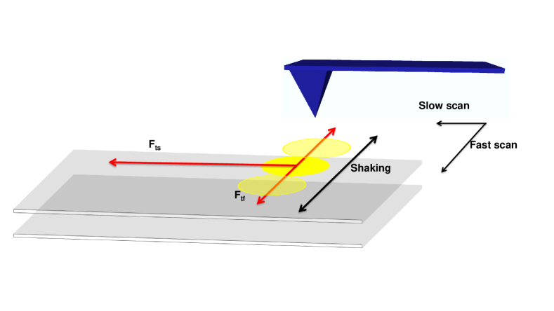
Appendix B Appendix II. Schematics of vortex motion induced by the magnetic tip
In the Supplementary Figure 6 we schematically discuss vortex motion produced by scanning the magnetic tip. The motion of the tip along the fast scan axis Supplementary Figure 6 shakes vortices out of their pinning potential, by inducing an oscillatory magnetic field variation with a frequency above the dynamic depinning transition. Then, the tip pushes vortices with a force in Supplementary Figure 6. The tip acts on the vortices along the slow scan axis with a force .
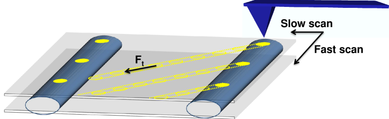
In Supplementary Figure 7 we schematically describe motion of pancake vortices decorating Josephson vortices. The motion is here just produced by the magnetic tip. The motion acquires a lateral drift that depends on the direction of the scan. In particular, on the side on which the tip first interacts with the vortex.
Appendix C Appendix III. Changing the tilt of the magnetic field
In Supplementary Figure 8 we show the result of modifying the direction of the in-plane magnetic field in an area where we have brought two Josephson vortices to cross each other. The experiments are made at low temperatures (about 5 K) and the magnetic field is of 200 G. When we heat up to 12 K we observe vortex wiggling, but the arrangement of crossing Josephson vortices remains about the same.
Appendix D Appendix IV. Moving pancake vortices along the tilt of the magnetic field
In Supplementary Figure 9 a-c we show vortex drag along the tilt of the magnetic field when there is no crossing. The area shows just a few pancakes, with no clearly discernible pinning at Josephson vortices. At 5 K, the tip alone is not enough to produce vortex motion. But when we apply a magnetic field perpendicular to the fast scanning direction, the vortex lattice becomes gradually more blurred along the tilt of the magnetic field. When the tilt of the magnetic field and the slow scanning axis coincide (Supplementary Figure 9 c), pancake vortices are dragged by the tip along the tilt of the magnetic field. Here, the dithering field of the scanning tip reduces pinning and allows for vortex motion, which occurs along the slow scanning direction (or here the tilt of the magnetic field). We use this experiment to estimate the attractive force between the tip and the pancake vortices as where is a numerical constant, is the dipolar moment per unit length of the tip, is an offset in the tip-sample separation and is the tip-sample distanceStraver2008 ; Auslaender2008 ; doi:10.1142/S0217979210056384 ; PhysRevB.80.054513 . We consider tip and vortices as magnetic monopoles. We find 80 pN. The Lorentz force by the Josephson currents acting on pancake vortices can be estimated to be of 50 pN, using the expected value of the currents in a Josephson vortexPhysRevB.68.094520 . Thus the forces needed to drag pancake vortices are about several tens to hundred pN at 5 K.
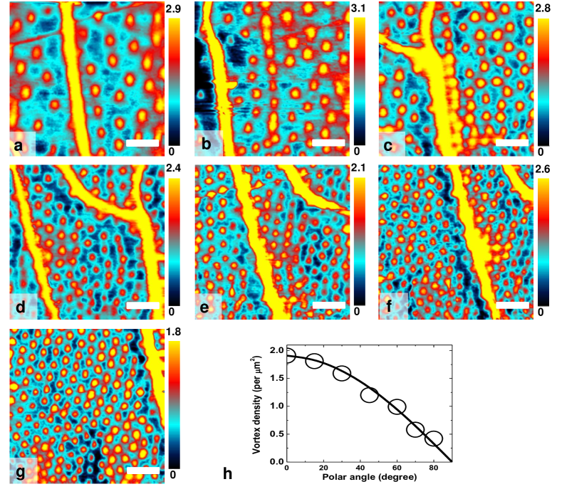
Appendix E Appendix V. Pancake vortex density when modifying the polar tilt
In the Supplementary Figure 10 a-g we show the evolution of the vortex lattice when changing the tilt of the magnetic field from nearly parallel to perpendicular to the layers, but having rapidly ramped up to close to the critical temperature after each change of the magnetic field. When the field is nearly perpendicular to the sample, the Abrikosov vortex lattice is hexagonal (Supplementary Figure 10 g). The density of pancake vortices follows expectations from the surface projection of the magnetic field when the field is tilted (Supplementary Figure 10 h). We observe linear structures with higher vortex density at all tilts, due to a long pinning center (Supplementary Figure a-g). It is useful to discuss the apparent vortex size. For instance, we observe in Supplementary Figure 10 d that pancake vortices lying close to the Josephson vortex on the left side of the image appear larger than those elsewhere. These vortices are attracted towards the pinning center, so that the corresponding dynamic depinning threshold is reduced and they feel more the oscillatory motion of the MFM tip than their neighbors.
Appendix F Appendix VI. Vortex size from MFM images and its temperature dependence
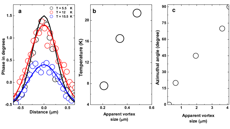
In the Supplementary Figure 11 we discuss the shape of vortices versus temperature. As we show in Supplementary Figure 11a, the usual shape of pancake vortices has a bell-like form which can be approximated by a Gaussian. When increasing temperature, the shape of the curve is modified. The contrast, as given by the change in phase in degrees, decreases and the curve flattens. We can define an apparent size of the pancake vortex and follow it as a function of temperature (as shown in Fig. 2 of the publication) and, for a fixed temperature, as a function of the in-plane direction of the magnetic field (Supplementary Figure 9). This value increases with temperature, as shown in Supplementary Figure 11b. Vortices become more blurred due to the combined action of the dithering magnetic field of due to the scanning MFM tip and the thermal excitation. When turning the magnetic field, the combined action of the Lorentz force and the dithering magnetic field of the MFM tip (Supplementary Figure 9) add together to produce blurred vortices (Supplementary Figure 11b).
Appendix G Appendix VII. Features in the surface that induce strong pinning
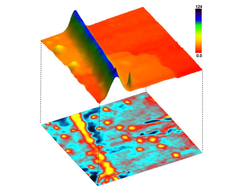
In the Supplementary Figure 12 we show a topography image made using the AFM mode together with one of the MFM images of the Figure 4 of the publication. The surface has clearly a very large wrinkle, of an approximate height of 100 nm. This features serves as a strong pinning center of vortices and allows that vortices remain there when modifying the in-plane direction of the magnetic field. This makes it possible to make the vortex manipulation experiment discussed in the Figure 4 of the publication.
References
- (1) Koshelev, A. E. Crossing lattices, vortex chains, and angular dependence of melting line in layered superconductors. Phys. Rev. Lett. 83, 187–190 (1999). URL http://link.aps.org/doi/10.1103/PhysRevLett.83.187.
- (2) Grigorenko, A., Bending, S., Tamegai, T., Ooi, S. & Henini, M. A one-dimensional chain state of vortex matter. Nature 414, 728 EP – (2001). URL https://doi.org/10.1038/414728a.
- (3) Curran, P. J. et al. Tuning the structure of the josephson vortex lattice in bi2sr2cacu2o8+d single crystals with pancake vortices. Scientific Reports 8, 10914 (2018). URL https://doi.org/10.1038/s41598-018-28681-7.
- (4) Buzdin, A. & Baladié, I. Attraction between pancake vortices in the crossing lattices of layered superconductors. Phys. Rev. Lett. 88, 147002 (2002). URL http://link.aps.org/doi/10.1103/PhysRevLett.88.147002.
- (5) Buzdin, A. & Simonov, A. Magnetic flux penetration into layered superconductors. Sov. Phys. JETP 71, 1165 (1990). URL http://www.jetp.ac.ru/cgi-bin/e/index/r/98/6/p2074?a=list.
- (6) Buzdin, A. & Simonov, A. Magnetization of anisotropic superconductors in the tilted magnetic field. Physica C: Superconductivity 175, 143 – 155 (1991). URL http://www.sciencedirect.com/science/article/pii/092145349190245T.
- (7) Grishin, A., Martynovich, A. & Yampol’skiy, S. Sov. Phys. JETP 70, 1089 (1990).
- (8) Grishin, A., Martynovich, A. & Yampol’skiy, S. The structure and elastic moduli of flux-line lattices in anisotropic superconductors. Sov. Phys. JETP 74, 355 (1992). URL http://www.jetp.ac.ru/cgi-bin/e/index/e/74/2/p345?a=list.
- (9) Hess, H. F., Murray, C. A. & Waszczak, J. V. Scanning-tunneling-microscopy study of distortion and instability of inclined flux-line-lattice structures in the anisotropic superconductor 2H-. Phys. Rev. Lett. 69, 2138–2141 (1992). URL https://link.aps.org/doi/10.1103/PhysRevLett.69.2138.
- (10) Gammel, P. L., Bishop, D. J., Rice, J. P. & Ginsberg, D. M. Images of the vortex chain state in untwinned crystals. Phys. Rev. Lett. 68, 3343–3346 (1992). URL https://link.aps.org/doi/10.1103/PhysRevLett.68.3343.
- (11) Kogan, V. G., Ledvij, M. & Bulaevskii, L. N. Vortex near the surface of an anisotropic superconductor: Implication for decoration. Phys. Rev. B 46, 8425–8428 (1992). URL https://link.aps.org/doi/10.1103/PhysRevB.46.8425.
- (12) Kogan, V. G. & Kirtley, J. R. Determining the vortex tilt relative to a superconductor surface. Phys. Rev. B 96, 174516 (2017). URL https://link.aps.org/doi/10.1103/PhysRevB.96.174516.
- (13) Tokunaga, M., Tamegai, T., Fasano, Y. & de la Cruz, F. Direct observations of the vortex chain state in by bitter decoration. Phys. Rev. B 67, 134501 (2003). URL http://link.aps.org/doi/10.1103/PhysRevB.67.134501.
- (14) Koshelev, A. E. Vortex-chain phases in layered superconductors. Phys. Rev. B 71, 174507 (2005). URL http://link.aps.org/doi/10.1103/PhysRevB.71.174507.
- (15) Matsuda, T. et al. Oscillating rows of vortices in superconductors. Science 294, 2136–2138 (2001). URL http://science.sciencemag.org/content/294/5549/2136. eprint http://science.sciencemag.org/content/294/5549/2136.full.pdf.
- (16) Vlasko-Vlasov, V. K., Koshelev, A., Welp, U., Crabtree, G. W. & Kadowaki, K. Decoration of josephson vortices by pancake vortices in . Phys. Rev. B 66, 014523 (2002). URL http://link.aps.org/doi/10.1103/PhysRevB.66.014523.
- (17) Grigorenko, A. N. et al. Visualization of interacting crossing vortex lattices in the presence of quenched disorder. Phys. Rev. Lett. 89, 217003 (2002). URL http://link.aps.org/doi/10.1103/PhysRevLett.89.217003.
- (18) Kirtley, J. R. Fundamental studies of superconductors using scanning magnetic imaging. Reports on Progress in Physics 73, 126501 (2010). URL http://stacks.iop.org/0034-4885/73/i=12/a=126501.
- (19) Suderow, H., Guillamón, I., Rodrigo, J. G. & Vieira, S. Imaging superconducting vortex cores and lattices with a scanning tunneling microscope. Superconductor Science and Technology 27, 063001 (2014). URL http://stacks.iop.org/0953-2048/27/i=6/a=063001.
- (20) Bulaevskii, L. N., Ledvij, M. & Kogan, V. G. Vortices in layered superconductors with josephson coupling. Phys. Rev. B 46, 366–380 (1992). URL https://link.aps.org/doi/10.1103/PhysRevB.46.366.
- (21) Bending, S. J. & Dodgson, M. J. W. Vortex chains in anisotropic superconductors. Journal of Physics: Condensed Matter 17, R955 (2005). URL http://stacks.iop.org/0953-8984/17/i=35/a=R01.
- (22) Segev, Y. et al. Suppression of geometrical barrier in Bi2Sr2CaCu2O8+δ crystals by josephson vortex stacks. Phys. Rev. B 83, 104520 (2011). URL http://link.aps.org/doi/10.1103/PhysRevB.83.104520.
- (23) Avraham, N. et al. Inverse melting of a vortex lattice. Nature 411, 451 EP – (2001). URL http://dx.doi.org/10.1038/35078021.
- (24) Straver, E. W. J., Hoffman, J. E., Auslaender, O. M., Rugar, D. & Moler, K. A. Controlled manipulation of individual vortices in a superconductor. Applied Physics Letters 93, – (2008). URL http://scitation.aip.org/content/aip/journal/apl/93/17/10.1063/1.3000963.
- (25) Auslaender, O. M. et al. Mechanics of individual isolated vortices in a cuprate superconductor. Nature Physics 5, 35 EP – (2008). URL https://doi.org/10.1038/nphys1127.
- (26) Le Doussal, P. Novel phases of vortices in superconductors. International Journal of Modern Physics B 24, 3855–3914 (2010). URL https://doi.org/10.1142/S0217979210056384.
- (27) Brandt, E. H., Mikitik, G. P. & Zeldov, E. Nanomechanics of an individual vortex in an anisotropic type-II superconductor. Phys. Rev. B 80, 054513 (2009). URL https://link.aps.org/doi/10.1103/PhysRevB.80.054513.
- (28) Embon, L. et al. Probing dynamics and pinning of single vortices in superconductors at nanometer scales. Scientific Reports 5, 7598 (2015). URL http://dx.doi.org/10.1038/srep07598.
- (29) Libál, A., Csíki, B. M., Reichhardt, C. J. O. & Reichhardt, C. Colloidal lattice shearing and rupturing with a driven line of particles. Phys. Rev. E 87, 022308 (2013). URL https://link.aps.org/doi/10.1103/PhysRevE.87.022308.
- (30) Kremen, A. et al. Mechanical control of individual superconducting vortices. Nano Letters 16, 1626–1630 (2016).
- (31) Schwarz, A., Liebmann, M., Pi, U. H. & Wiesendanger, R. Real space visualization of thermal fluctuations in a triangular flux-line lattice. New Journal of Physics 12, 033022 (2010). URL http://stacks.iop.org/1367-2630/12/i=3/a=033022.
- (32) Pérez Daroca, D., Pasquini, G., Lozano, G. S. & Bekeris, V. Dynamics of superconducting vortices driven by oscillatory forces in the plastic-flow regime. Phys. Rev. B 84, 012508 (2011). URL https://link.aps.org/doi/10.1103/PhysRevB.84.012508.
- (33) Koshelev, A. E. Josephson vortices and solitons inside pancake vortex lattice in layered superconductors. Phys. Rev. B 68, 094520 (2003). URL http://link.aps.org/doi/10.1103/PhysRevB.68.094520.
- (34) Kalisky, B. et al. Flux-flow resistivity anisotropy in the instability regime of the plane of epitaxial superconducting thin films. Phys. Rev. Lett. 97, 067003 (2006). URL https://link.aps.org/doi/10.1103/PhysRevLett.97.067003.
- (35) Blatter, G., Feigel’man, M. V., Geshkenbein, V. B., Larkin, A. I. & Vinokur, V. M. Vortices in high-temperature superconductors. Rev. Mod. Phys. 66, 1125–1388 (1994). URL https://link.aps.org/doi/10.1103/RevModPhys.66.1125.
- (36) Nelson, D. R. Vortex entanglement in high- superconductors. Phys. Rev. Lett. 60, 1973–1976 (1988). URL https://link.aps.org/doi/10.1103/PhysRevLett.60.1973.
- (37) Olson Reichhardt, C. J. & Hastings, M. B. Do vortices entangle? Phys. Rev. Lett. 92, 157002 (2004). URL https://link.aps.org/doi/10.1103/PhysRevLett.92.157002.
- (38) Schönenberger, A., Geshkenbein, V. & Blatter, G. Vortex entanglement and broken symmetry. Phys. Rev. Lett. 75, 1380–1383 (1995). URL https://link.aps.org/doi/10.1103/PhysRevLett.75.1380.
- (39) Marchetti, M. C. & Nelson, D. R. Hydrodynamics of flux liquids. Phys. Rev. B 42, 9938–9943 (1990). URL https://link.aps.org/doi/10.1103/PhysRevB.42.9938.
- (40) Sudbø, A. & Brandt, E. H. Flux-line cutting in superconductors. Phys. Rev. Lett. 67, 3176–3179 (1991). URL https://link.aps.org/doi/10.1103/PhysRevLett.67.3176.
- (41) Moore, M. A. & Wilkin, N. K. Energy cost associated with vortex crossing in superconductors. Phys. Rev. B 50, 10294–10301 (1994). URL https://link.aps.org/doi/10.1103/PhysRevB.50.10294.
- (42) López, D. et al. Pinned vortex liquid above the critical point of the first-order melting transition: A consequence of pointlike disorder. Phys. Rev. Lett. 80, 1070–1073 (1998). URL https://link.aps.org/doi/10.1103/PhysRevLett.80.1070.
- (43) Luan, L. et al. Magnetic force microscopy study of interlayer kinks in individual vortices in the underdoped cuprate superconductor . Phys. Rev. B 79, 214530 (2009). URL https://link.aps.org/doi/10.1103/PhysRevB.79.214530.
- (44) Sudbø, A. & Brandt, E. H. Nonlocal elastic properties of flux-line lattices in anisotropic superconductors in an arbitrarily oriented field. Phys. Rev. B 43, 10482–10488 (1991). URL https://link.aps.org/doi/10.1103/PhysRevB.43.10482.
- (45) Mirković, J., Savel’ev, S. E., Sugahara, E. & Kadowaki, K. Stepwise behavior of vortex-lattice melting transition in tilted magnetic fields in single crystals of . Phys. Rev. Lett. 86, 886–889 (2001). URL https://link.aps.org/doi/10.1103/PhysRevLett.86.886.
- (46) Mirković, J., Savel’ev, S. E., Sugahara, E. & Kadowaki, K. Anisotropy of vortex-liquid and vortex-solid phases in single crystals of violation of the scaling law. Phys. Rev. B 66, 132505 (2002). URL https://link.aps.org/doi/10.1103/PhysRevB.66.132505.
- (47) Galvis, J. A. et al. Three axis vector magnet set-up for cryogenic scanning probe microscopy. Review of Scientific Instruments 86, – (2015). URL http://scitation.aip.org/content/aip/journal/rsi/86/1/10.1063/1.4905531.
- (48) Horcas, I. et al. Wsxm: A software for scanning probe microscopy and a tool for nanotechnology. Review of Scientific Instruments 78, 013705 (2007). URL https://doi.org/10.1063/1.2432410. eprint https://doi.org/10.1063/1.2432410.
- (49) Koshelev, A. E. & Dodgson, M. J. W. Josephson vortex lattice in layered superconductors. Journal of Experimental and Theoretical Physics 117, 449–479 (2013). URL https://doi.org/10.1134/S1063776113110125.
- (50) Campbell, L. J., Doria, M. M. & Kogan, V. G. Vortex lattice structures in uniaxial superconductors. Phys. Rev. B 38, 2439–2443 (1988). URL https://link.aps.org/doi/10.1103/PhysRevB.38.2439.