The WIYN One Degree Imager in 2018: An Extended 30-Detector Focal Plane
Abstract
We report on the upgraded One Degree Imager (ODI) at the WIYN 3.5 meter telescope at the Kitt Peak Observatory after the focal plane was expanded by an additional seventeen detectors in spring 2015. The now thirty Orthogonal Transfer Array CCD detectors provide a total field of view of 40’ x 48’ on the sky. The newly added detectors underwent a design revision to mitigate reduced charge transfer efficiency under low light conditions. We discuss the performance of the focal plane and challenges in the photometric calibration of the wide field of view, helped by the addition of telescope baffles. In a parallel project, we upgraded the instrument’s three filter arm mechanisms, where a degrading worm-gear mechanism was replaced by a chain drive that is operating faster and with high reliability. Three more filters, a u’ band and two narrow band filters were added to the instrument’s complement, with two additional narrow band filters currently in procurement (including an H filter). We review the lessons learned during nearly three years of operating the instrument in the observatory environment and discuss infrastructure upgrades that were driven by ODI’s needs.
keywords:
Ground based instrumentation, wide field imaging, CCD, Orthogonal Transfer Array, Observatory Operations, WIYN Observatory1 Introduction
The One Degree Imager (ODI) has been the major instrument development project from 2002 to 2015 at the WIYN 3.5 meter telescope (Kitt Peak, Arizona), and its design and progress has been documented in various SPIE conference contributions [1, 2, 3, 4, 5, 6, 7, 8, 9]. The instrument is designed for a one degree square field of view with 64 Orthogonal Transfer Array (OTA) CCD sensors. OTA detectors[10, 11] were developed to move charge in both dimension on the detector during a science integration, allowing to actively compensate for image motion caused by telescope tracking errors or even atmospheric turbulence by applying corrections within an isokinetic patch size of about 4 arc minutes on sky; this latter concept was dubbed ”rubber focal plane” by Tonry et al. (2002) [12]. ODI was designed to deliver atmospheric limited image quality even under the best possible observing conditions.
A first incarnation of ODI was deployed in the summer of 2012 with a partially populated focal plane with 13 out of 64 detectors installed in a central 3 3 array, and four detectors placed to asses the image quality over the field of view. This incarnation of ODI was called pODI and was described in detail at the SPIE Astronomical Telescopes + Instrumentation conference in 2014[8]. pODI demonstrated that the instrument indeed delivered better than 0.4” images over the entire field of view in the g’, r’, i’, and z’ passbands.
In 2015, ODI was upgraded and redeployed at WIYN with an enlarged 5x6 detector array by adding 17 new detectors, providing a contiguous field of view of on sky; this incarnation of ODI is generally referred to as ”5x6 ODI”, or simply ODI, as no additional development of the focal plane is planned at this point. In this paper we report on the status of the instrument and the upgrade process.
2 Upgrade of the Instrument
ODI is designed to use Orthogonal Transfer Array (OTA) CCD detectors that have the unique capability to move charge on both imaging dimensions during an integration in order to compensate for unwanted image motion. This concept has been demonstrated in pODI. The detectors in pODI (production Lot 6) had problems with (i) amplifier glow and (ii) charge transfer efficiency under low light level conditions (”fat zero” problem). The amplifier glow is mitigated by throttling the output drain voltage of the detectors during integration. The fat zero problem was traced to a structure between the imaging area and the serial output register.
A 12 wafer demonstration run (Lot 7) showed that the low light level transfer inefficiency issue was resolved by a modification[8], and subsequently all wafers of that lot were processed into packaged detectors at Imaging Technology Laboratory (ITL, Tucson, AZ). The 48 detector dies on the 12 wafers (there are 4 OTA dies on each wafer) yielded a total of 16 operational Lot 7 OTA detectors designated for the ODI focal plane. After processing these wafers, the processing equipment for ODI OTA detectors was retired at ITL.
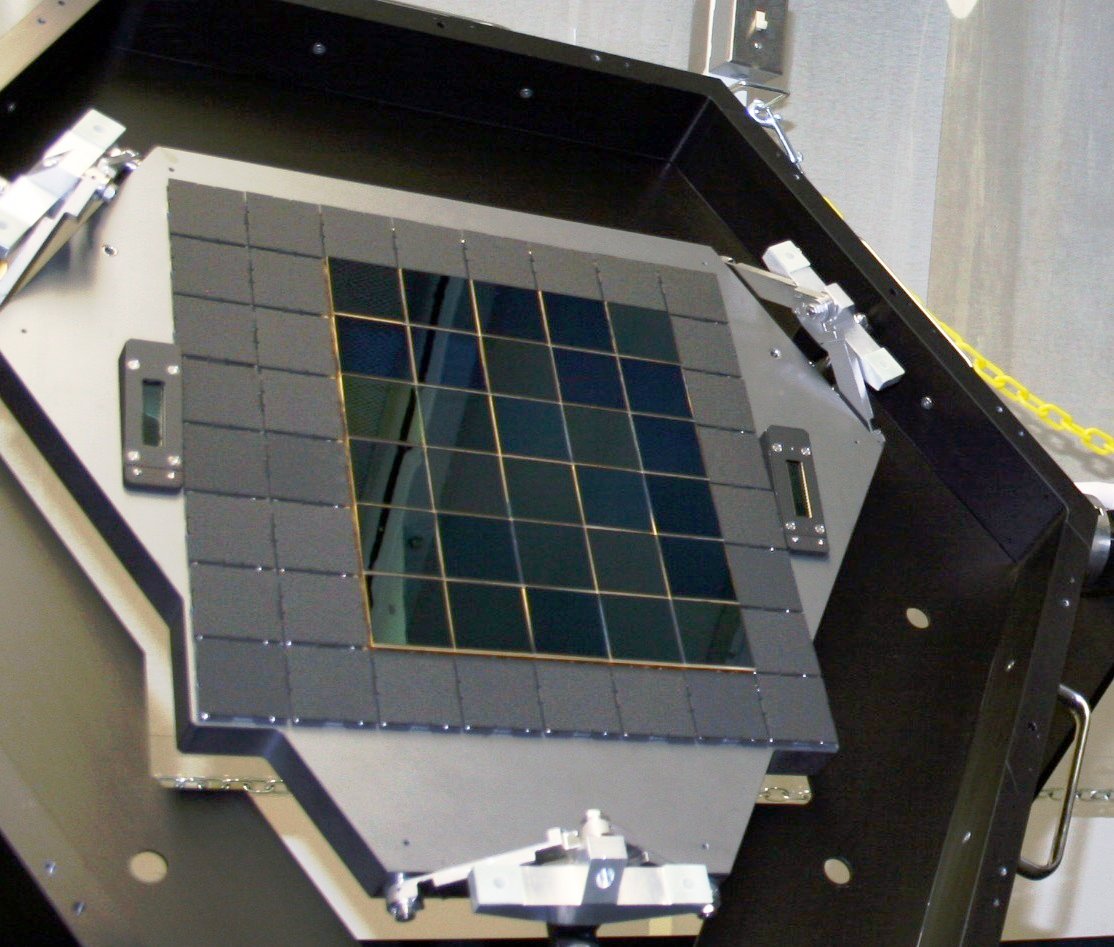
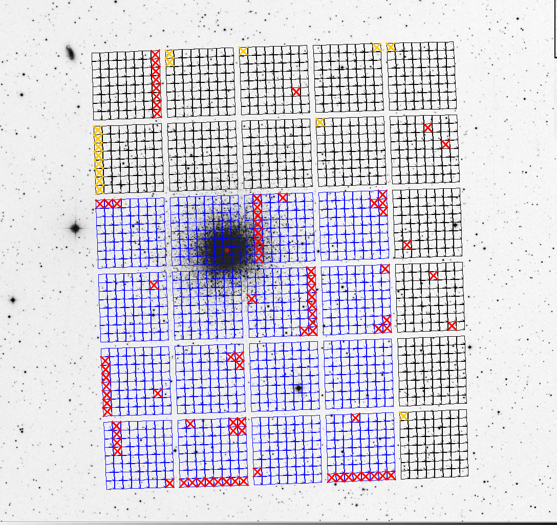
The instrument was taken out of commission for upgrading from November 2014 to May 2015. The focal plane was immediately removed from the instrument and sent to Imaging Technology Laboratory to add the 16 new detectors; an additional Lot 6 device was identified and added to the focal plane as well. The 14 Lot 6 and 16 Lot 7 detectors were mounted on the focal plane to result in a contiguous central 4x4 area of Lot 7 detectors, with the remaining Lot 6 detectors filling up the surrounding area to produce a 5 by 6 detector array (See Figure 1).
While the focal plane was repopulated with detectors, the cryostat and the instrument hardware were refurbished. We found in particular:
-
•
Some epoxy-sealed vacuum feed throughs had developed leaks. We attribute those to the thermal cycling caused by the nearby CCD controllers. The daytime idle position of the instrument was changed to prevent the formation of heat pockets near the vacuum seals, and to allow a better convective cooling flow in the CCD controller chassis.
-
•
Inside the dewar we have identified areas of outgassing residue, which were cleaned.
-
•
The optical surfaces of ODI’s corrector optics needed cleaning, including the inside of the cryostat’s dewar window.
-
•
The lubricant in a ring bearing for the atmospheric dispersion corrector (ADC) prism had separated, and the liquid oil component started to flow over one of the prisms. The optics were cleaned with no detrimental effect to the surface and its anti-reflection coating. Since the ADC bearings operate only at a very slow speed, the lubricant was entirely removed from the ring bearings to avoid the risk of future leaks.
-
•
At the time of the dewar refurbishment, the molecular sieve material in the dewar (Zeolite 5-A) saturated (presumably with water), leading to an unmanageably short vacuum hold time of a few days, and it was hence replaced with fresh 5-A material. In the past, the Zeolite 5-A had been replaced on an annual basis due to its saturation. Since replacing the Zeolite in the dewar is an expensive and labour intensive operation, we started to investigate hydrophobic Zeolite ZSM-5 as a replacement candidate. Since ZSM-5 does not permanently bind water as 5-A does, it can be regenerated by vacuum pumping at room temperature alone, without the need for high temperature backing.
In January 2017 the ODI molecular sieve material was replaced with Zeolite ZSM-5. After over a year in operation, the ZSM-5 material still performs well and shows no signs of degradation. We note that the ODI dewar is warmed up and vacuum-pumped on a regular basis (every few months), which regenerates the ZSM-5’s ability to adsorb gas.
2.1 Focal Plane Performance
As expected, the Lot 7 OTA detectors performed similarly to the Lot 6 detectors, but without displaying the low light level charge transfer efficiency problem. Since the 5x6 ODI focal plane utilizes both Lot 6 and Lot 7 detectors, observations that depend on the full field of view still require a minimum background level of the order of 100 electrons, which sets a lower limit on the useful exposure time. If the smaller field of view of the continuous Lot 7 sub-array is sufficient for the scientific goals of an observation, those restrictions do not apply. The amplifier glow in the ODI OTA detectors remains unchanged, and, as in pODI, it is mitigated by throttling the output drain (OD) voltage while idling or integrating light, and only turning it fully on during the readout of a detector. Detectors that are used for guiding during an exposure have their OD turned fully on. This contaminates large parts of that detector with amplifier glow, making it unusable for science for that exposure.
Changing the OD of the OTA detectors during integration and idling versus reading out leads to a change in their power dissipation. We estimated the difference between the OD throttled and fully on to be about 0.5W per detector. Reading the detectors while OD is fully on will hence dissipate an additional 15 Watts into the focal plane for the read time of about 6 seconds. This causes temperature variations in the focal plane of the order of several tenths of to a full degree Kelvin, in particular during high cadence use cases. While the total cooling power of the ODI focal plane would be sufficient to cool a focal plane that was fully populated with 64 OTA detectors, the accuracy of the temperature control might not meet the specifications with a full compliment of OTA detectors.
The Stargrasp CCD controller[13] used in ODI can control one or two detectors per board. For pODI, a maximum of one detector was connected per controller board, and the cross-talk behavior for two connected detectors was not yet demonstrated in pODI. In the 5x6 ODI focal plane, 2/3 of the detectors share a controller board, whereas 1/3 of the detectors are controlled by a single Stargrasp board each. No evidence of cross-talk between the two channels of a Stargrasp board was found.
The detectors in the pODI instrument were placed to sparsely sample the entire 1x1 degree field of view of ODI, and the delivered image quality of pODI was found to be better than 0.4” on sky over the entire field of view in the ODI g’,r’,i’, and z’ band filters. The same performance was confirmed for the 5x6 ODI focal plane, i.e., the alignment was reproduced when the focal plane was removed and reinstalled into the dewar for the detector upgrade.
Further details about the instrument performance are described in the ODI User’s Manual111http://www.wiyn.org/ODI.
2.2 Tuning the acquisition software
The ODI data acquisition software is described in detail in previous SPIE contributions[4, 7]. In short, the 5x6 ODI focal plane is read out by 20 Stargrasp CCD controllers which interface to a network switch via individual 1GB ethernet over fiber connections. The switch itself bundles the data connection into a 10GB network backbone used by the ODI computers (three units with 24 cores, 32GB RAM each). The data stream from the 30 CCDS is collected by a single server / Java virtual machine that is managed by a JBOSS 5 application server. From there, data are saved to a storage device.
The data rate has more than doubled (from 13 detectors to now 30) to about 1 Gigabyte that downloads from the detectors in about 6 seconds. The scalability of the data acquisition system was tested before the upgrade by creating a virtual focal plane configuration to simulate the enlarged focal plane. This test revealed some bottlenecks: the interval between sustained bias readouts increased from about 25 seconds to over 40 seconds. Several bottlenecks in the data acquisition code were identified and mitigated during the upgrade project and commissioning phase:
-
1.
For pODI, all data were saved directly to an NFS-mounted storage devices (Oracle ZFS appliance) and the delay in writing FITS files to disk was the major factor slowing the data handling process. As a mitigation we equipped the acquisition server with a Raid 5 configured local storage array, utilizing only disks with a 6G interface; new images are now first stored on the local hard drives. The image data are then slowly transferred by a background process to the storage appliance, which serves both as a mid-term storage and to stage data for transfer into the ODI data archive.
-
2.
Simultaneously receiving the data streams from 30 detectors via TCP/IP posed no major challenge for the 10GB network backbone. However, when writing the data to disk we realized a significant improvement in the write speed by limiting the number of data streams that are written in parallel to disk. As a mitigation, the FITS file writing routine was changed into a Java Callable that would be submitted to a multi-threaded Executor, and we determined that ten storage threads delivered a good performance. The write performance was further improved by rewriting the nom.tam.fits package to allow writing into BufferedOutputfile.
-
3.
As part of the data storage process, a thumbnail image is generated for each detector to help the observer to judge image quality in real time. For pODI, the thumbnail generation was delegated to a command line utility that was called after the images were written to disk, reading back (and decoding) the FITS file again. Also, the thumbnail generation process was unnecessarily serialized in the data acquisition process, i.e., telescope observations would be blocked until thumbnail images were generated. For 5x6 ODI we have moved the thumbnail generation into the Java virtual machine, where the data are already in memory, hence saving I/O and CPU time for FITS decoding. Furthermore, the generation of the thumbnails was delegated to lower priority background threads, making the thumbnail generation an asynchronous process.
As indicated by prior testing, the existing IT infrastructure was capable of handling the larger focal plane after some investments into faster local storage and by serializing the data storage processes. After each readout, about 6 seconds are spent to flush the detector to remove residual charge, and the readout overhead is now limited by the detector and telescope performance.
2.3 Advanced OTA modes
Over the time of the ODI project we have demonstrated that OTA detectors can successfully compensate for tip / tilt image motion at an approximate 20Hz rate by moving charge on the detector; this ability was the original motivation to utilize OTA detectors in ODI. However, the amplifier glow in ODI’s OTAs prohibits the use of a detector for simultaneous guide star acquisition and science integration; localized atmospheric image motion compensation within an isokinetic patch (about 4 arcminutes on sky, or a quarter section of a single OTA detector) is hence not practical. Even if the amplifier glow were to be addressed successfully, there are practical limitations to implementing a rubber focal plane as envisioned in Tonry et al. (2002)[12]. The density of bright guide stars is insufficient in some optical passbands, in particular outside the galactic plane. It is not sufficiently established how one would proceed with the astrometric calibration of such a rubber focal plane, and the data processing effort would be significant for a modest improvement in delivered image quality. Neither the PanSTARRS survey nor the ODI instrument have advanced the rubber mode into turn-key operations.
The on-chip image motion compensation for ODI can still be useful to correct for telescope tracking errors or light wind shake by sensing the average motion of several guide stars, e.g., at the corners of the field of view; averaging their signal would ignore localized atmospheric turbulence. We call this the ”coherent guide mode”[8]. This observing mode is implemented in the ODI software and theoretically usable by observers on demand, but at this time there is no support in the data processing pipeline. Also, ideally one would use three to four bright guide stars in the corners of the field of view; since the use of a detector for guide star acquisition requires the output drain to be turned on during the exposure, amplifier glow will render those detectors unsuitable for science use, reducing the usable science field of view. To date, the coherent guide mode has not gained traction beyond the technical demonstration.
3 Filter change mechanism upgrade and performance
ODI has a filter change mechanism that can hold up to nine filters, where each filter is about in size. Each filter is inserted and removed out of the beam by a semaphore-like filter arm that was originally driven by a worm gear[5]. Due to the proximity to optical surfaces, the worm gear contact was operating without lubrication (steel on bronze contact). During integration testing of pODI in 2012 it was realized that this drive would not be viable for long-term operations, as the stainless steel worm gear would slowly shave off the bronze gear on the filter arm. However, due to time and resource constraints, pODI was deployed as it was with the understanding that this issue would have to be addressed eventually. In the meantime, the bronze gear was replaced on an annual basis due to wear and tear, but even with fresh gears operation was unreliable because of increased friction, and occasionally bronze shavings caused short circuits in the filter arm position sensors.
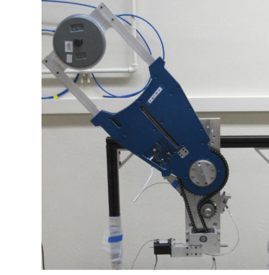
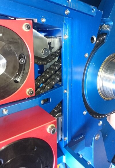
In 2014 we started a project to redesign the filter drive, where instead of a worm gear the filter arm would be driven directly by a chain drive. The original custom-made gear box of the filter drive was replaced by a commercial, encapsulated lubricated worm gear. A single chain-driven filter arm prototype was designed and built at the University of Wisconsin-Madison (Figure 2, left), and its operation was successfully demonstrated by over in/out 6000 actuations under several spatial orientations. After testing, the worm gear box was taken apart and inspected for signs of excessive wear - none could be identified.
Upon successful testing, a full complement of nine filter drives (three units that serve three filter arms each) was built at the NOAO instrument shop, and the upgraded filter drive was installed into the ODI instrument during the summer of 2015 (see Figure 2, right). The new drive has worked without problems ever since.
4 Stray light and mitigation by additional baffles
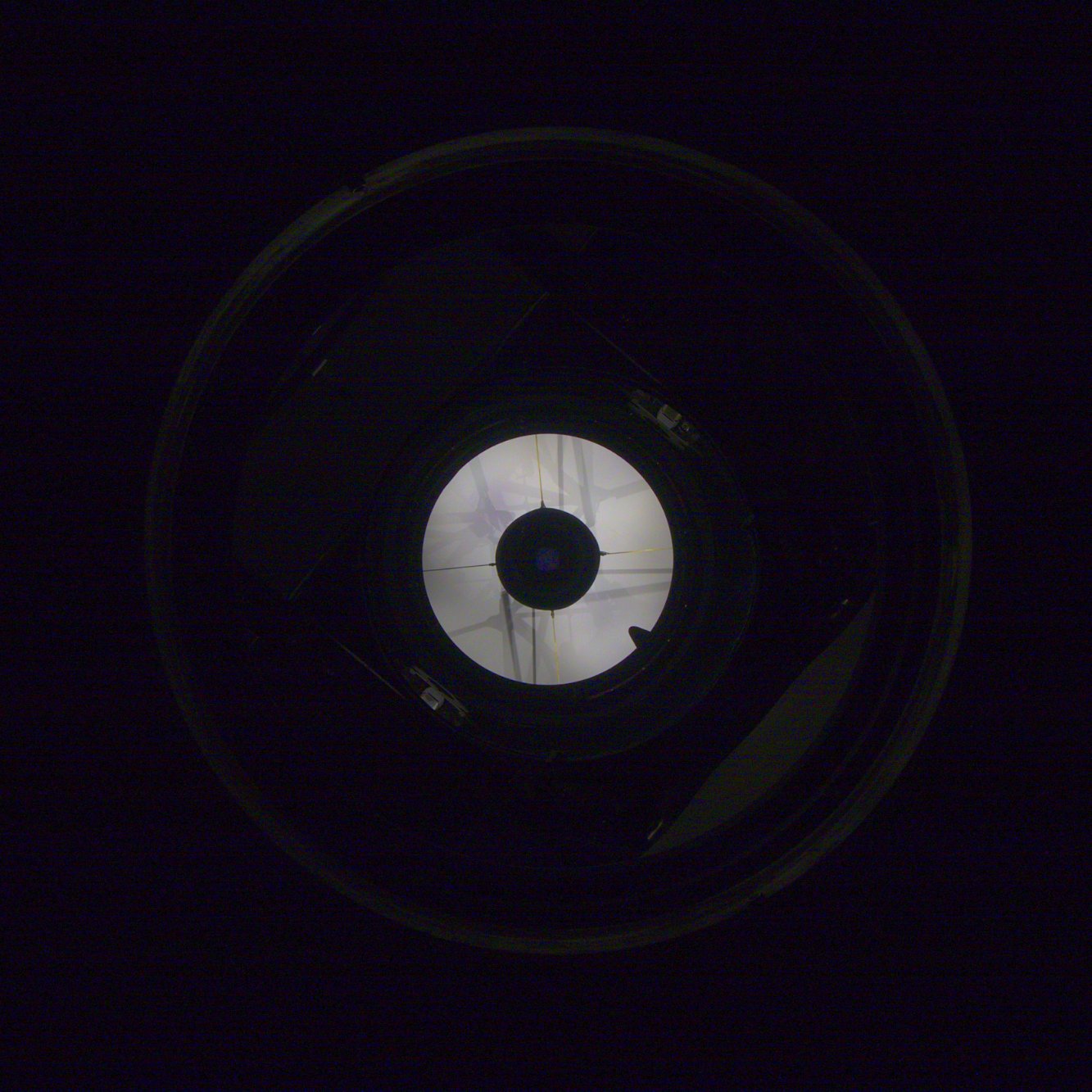
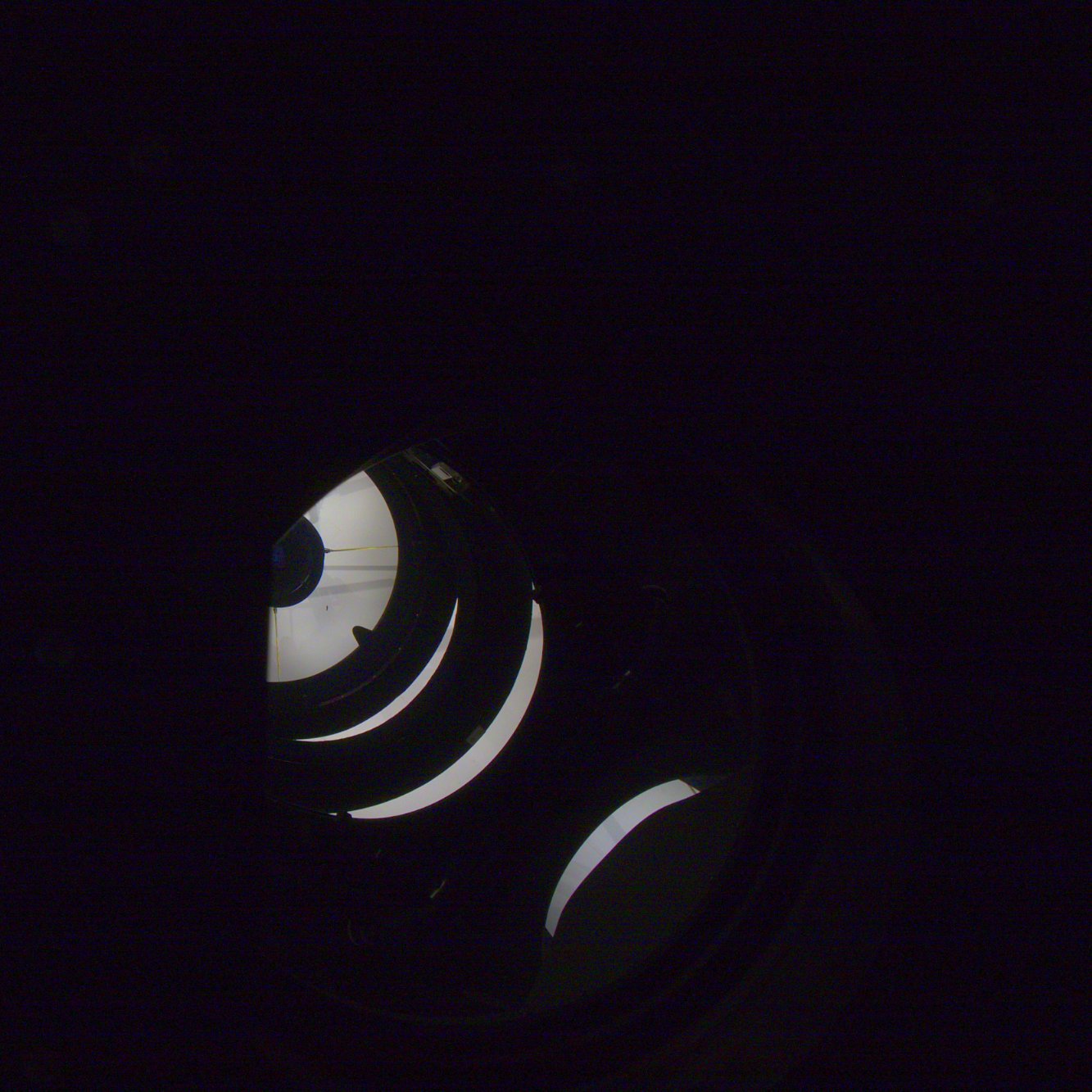
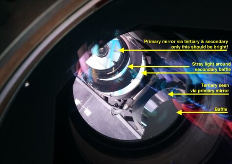
In advance of pODI’s original deployment, a detailed stray light analysis executed by Photon Engineering (Tucson, AZ) indicated that a significant contribution of stray light was to be expected on the ODI focal plane. The two major contributors are (i) off-axis rays reflecting off the tertiary mirror, then the primary mirror, finally entering the instrument and (ii) off-axis rays reflecting directly off the tertiary mirror, entering the instrument. The first stray light mode had already been addressed by installing an additional baffle at the entrance aperture of pODI. The latter stray light path, however, had not been mitigated yet by the time of the 5x6 ODI upgrade. The origin of the stray light is clearly visible in Figure 3, where we show the view through the instrument (with the dewar removed) at the center and upper left corner of the field of view.
For the initial pODI deployment with a smaller focal plane the stray light did not significantly affect operations since the affected area was barely covered by detectors; the extended focal plane of 5x6 ODI however was strongly affected by the second stray light path, where the stray light contribution to the background is of order of 30%. For night time observations the stray light manifests in additional background structure that can be subtracted; for the acquisition of flat field calibration images the stray light is detrimental.
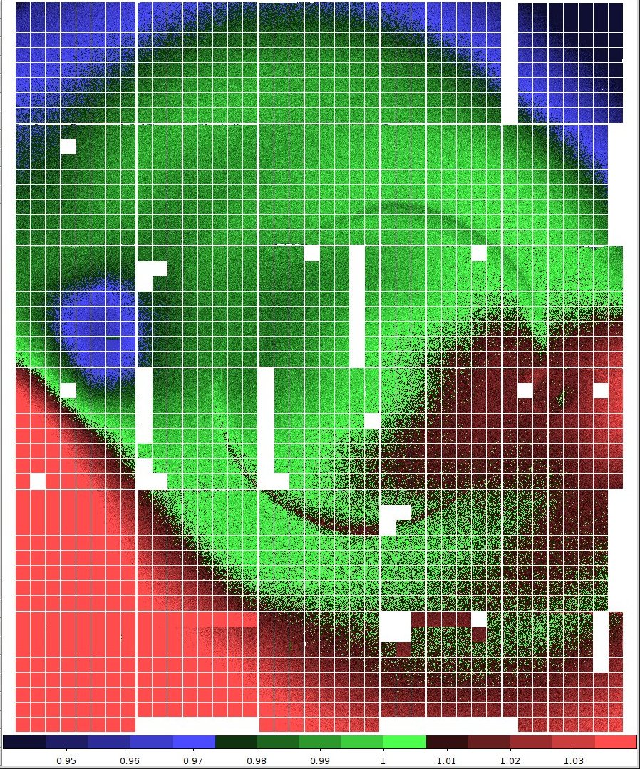
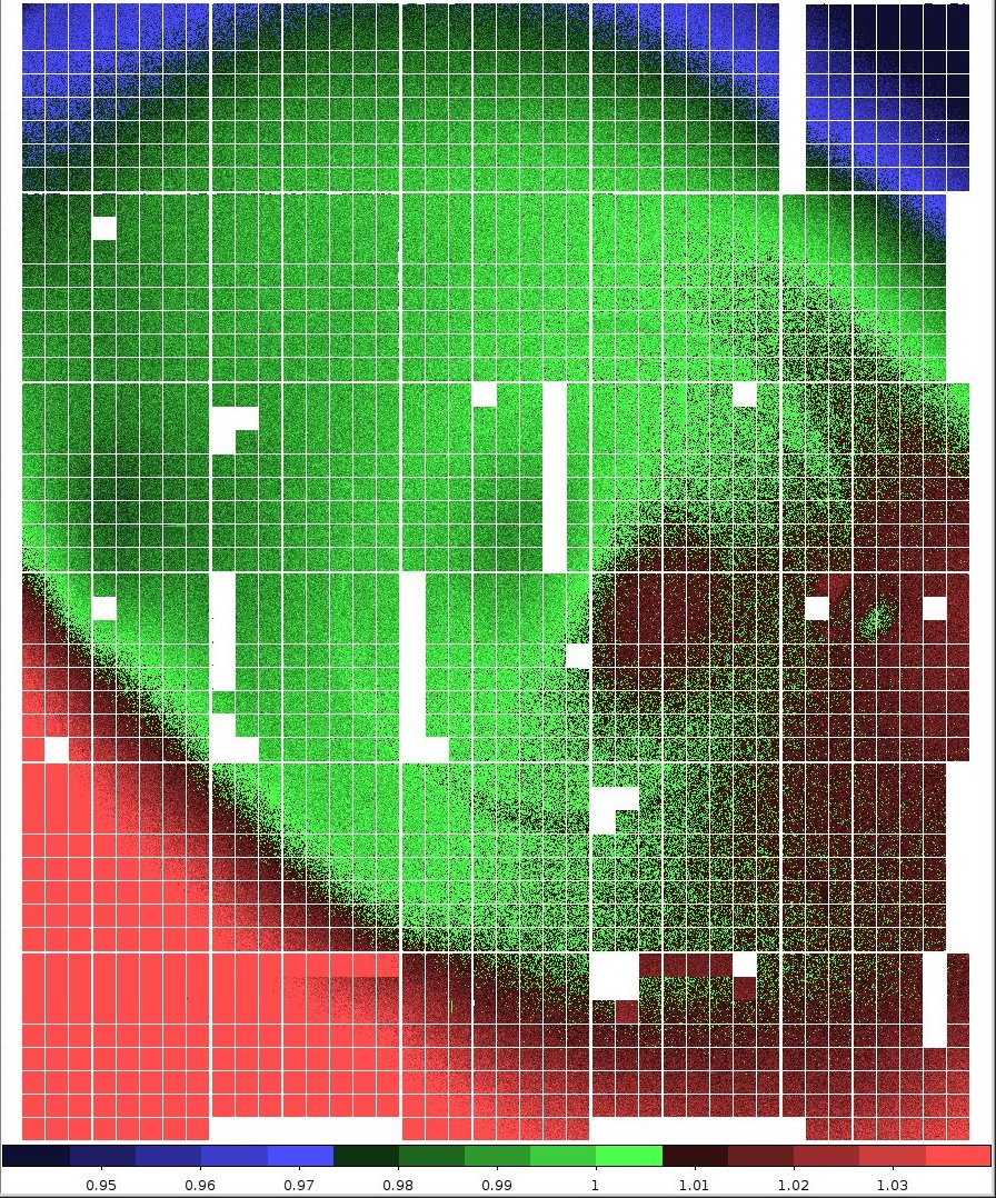
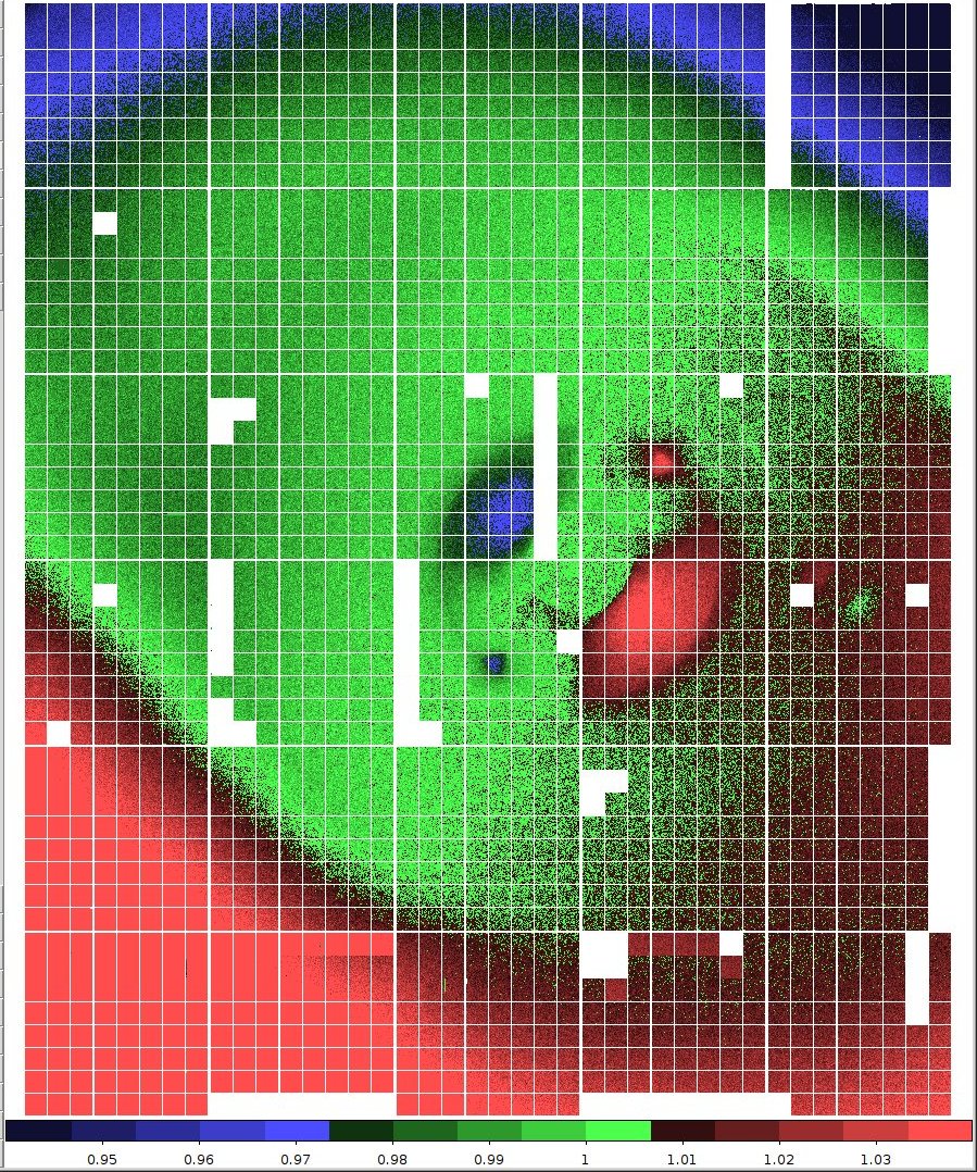
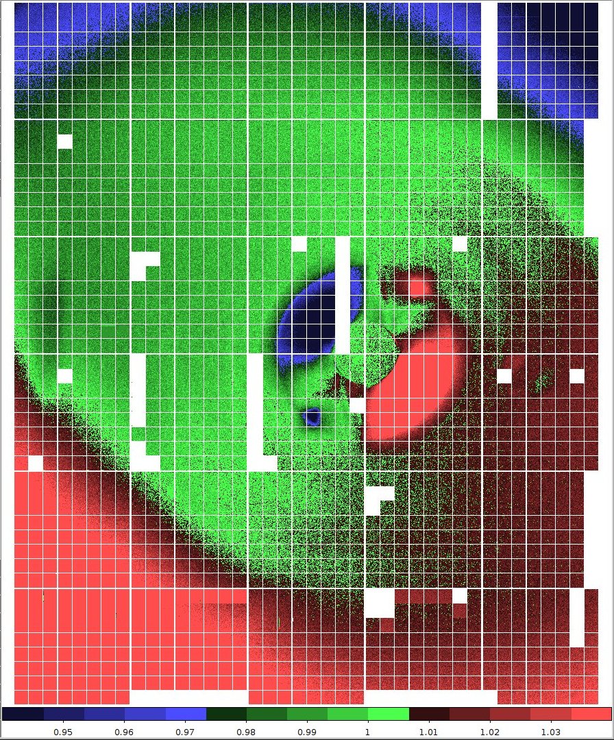
| odi u’ | odi g’ | odi r’ | od i’ | odi z’ |
| ratio of flat fields, no baffle | ||||
 |
 |
 |
 |
 |
 |
 |
 |
 |
 |
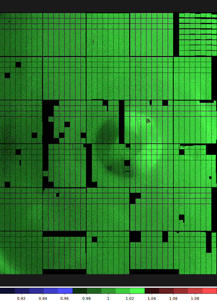
| ratio of flat fields, with baffle | ||||
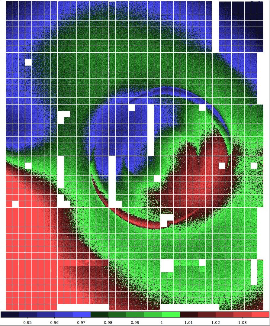
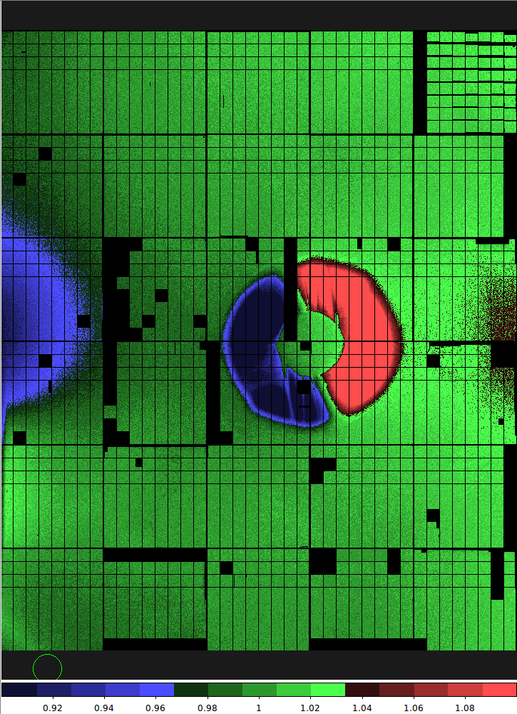
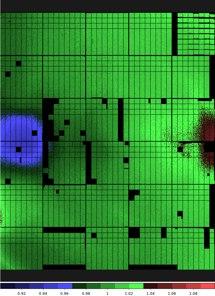
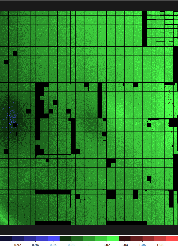
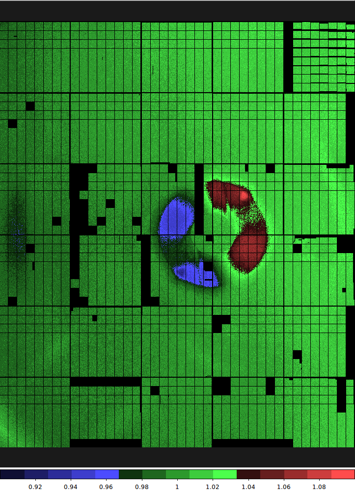
The stray light can be readily identified by comparing flat fields that are taken at different instrument rotations. We demonstrate this in Figure 4, where for a set of the g’r’i’z’ filters we show the ratio of dome flats that were taken with a nominal instrument rotation of plus and minus 90 degrees. In case of a flat illumination, one would expect a constant ratio of unity in those images. The flat field ratios however show a strong sign of (i) central pupil ghosts (see next section) and (ii) stray light in the lower left corner.
The stray light was mitigated by installing two additional baffles at the telescope according to Photon Engineering’s recommendation: one larger ring baffle around the tertiary mirror, and one slim ring around the secondary baffle. These baffles sufficiently block the stray light paths that can be seen in Figure 3. The new baffles increase the central obscuration of the telescope, causing a 2.3% loss in collected light. For this reason, the baffles were designed to allow for quick removal when using narrow field instruments that are not adversely affected by the stray light. While not studied, we expect that the Hydra fiber fed spectrograph located on the opposite Nasmyth port at the WIYN telescope will benefit from the baffles as well.
5 Pupil ghost suppression using a two bladed shutter
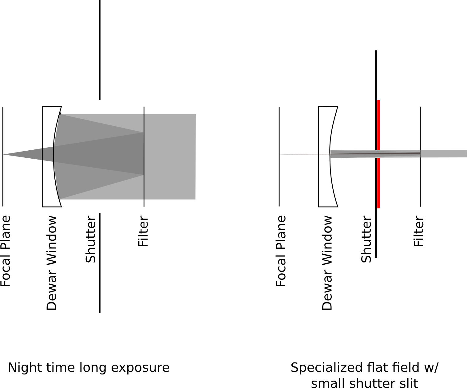
Reflections of the optical surfaces within ODI produce internal ghosting that contaminates flat field calibration and science exposures. The major contributing light path is a reflection of ODI’s concave dewar window, that is then back reflected at a flat filter to form an image of the telescope pupil on the focal plane (Figure 5). Thanks to anti-reflection coatings on the optics, each reflection is suppressed to a 1%-2% level, depending on the actual wavelength of the light, but the residual light is still capable of producing a significant ghosting component. Due to the wavelength-dependent performance of the anti-reflection coating, the pupil ghost is more pronounced at shorter wavelengths. Also, since the pupil ghost forms by reflection of a band pass filter, and the ODI filters are arranged in three layers, the size and hence concentration of the pupil ghost will change with the in-beam filter.
The pupil ghost is undesirable for several reasons: In night-sky observations it will produce an extra background component, albeit one that can be mitigated by subtracting out a model. More severely, the pupil ghost also produces an extra light component in a calibrating flat field, and if not corrected, would lead to a false sensitivity calibration of the affected areas.
The first approach to removing the pupil ghost from calibration images was to model the ghost image and to then subtract a scaled model from flat field images. This method was overall successful, but was prone to adding noise and leaving sharp residual errors. It remains desirable to avoid the pupil ghost formation in the first place.
The pupil ghost was found to be greatly suppressed by the ODI shutter222ODI uses a Bonn Shutter, http://www.bonn-shutter.de when the exposure time was very short (less than 0.1 seconds), and the shutter’s blades would obstruct most of the optical path in front of the dewar window; only a narrow slit then moves over the focal plane. This suppression mechanism is illustrated by Figure 5, left. Despite the shutter forming only a narrow slit, the direct illumination of the focal plane is identical to a flat field where the shutter completely opens.
This ghost-suppressing behavior of the shutter has been exploited already by using very short exposure times of order of 50ms for sky flat fields, obsoleting the need to remove a ghost model from flat fields. But this method is limited to cases where enough light is available for flat fielding; narrow band filters cannot be easily calibrated this way.
We have circumvented the limitation to very short calibration exposure times by drastically lowering the travel speed of the shutter blades during flat field exposures. The travel time of the shutter blades across the focal plane is increased to approximately 27 seconds from the factory default of 0.75 seconds. Now a narrow slot slowly crosses the field of view, allowing effective exposure times of several seconds.
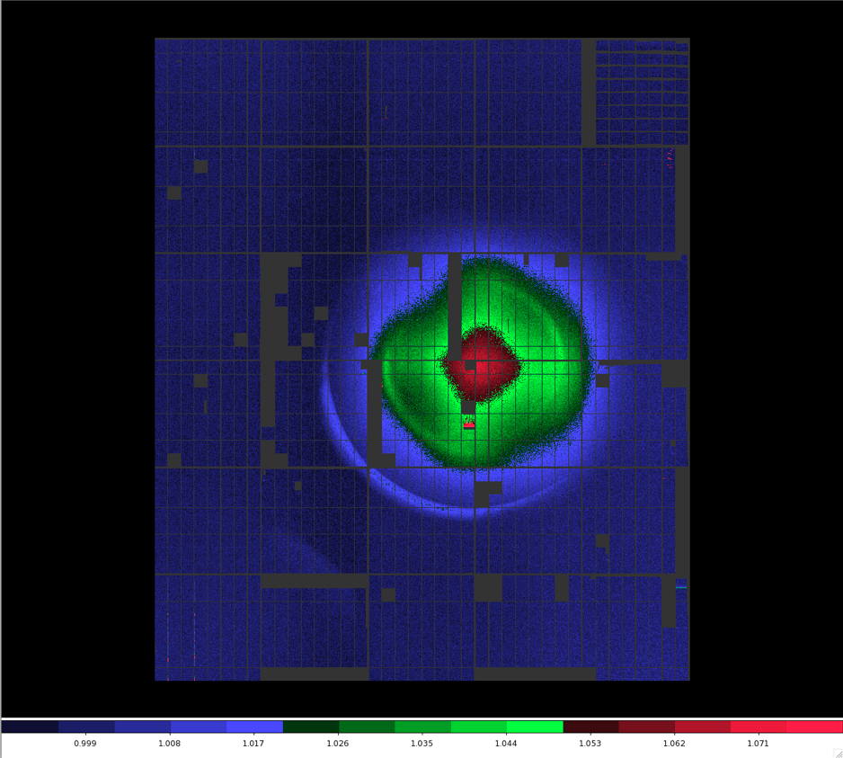
A good demonstration of the pupil ghost suppression by the shutter is to divide a flat field where the shutter is operated conventionally by a flat field where the shutter operated in the slow narrow-slit mode. Only the extra pupil ghost component remains visible in the image (Figure 5).
All dome flat fields are now acquired using the slow shutter mode, which has eliminated the need to model and subtract the pupil ghost and other more complex instrument-internal reflections from flat field calibration images.
6 Condensation
A major operational limitation of ODI is the susceptibility of the dewar window to condensation. As the condensation itself will evaporate quickly under dryer conditions, we have found that, inevitably, a significant thin film of residue was left behind, following a condensation event, that could only be removed by cleaning the dewar window (specifically, drag wiping the surface with alcohol). The effect of the residue is detrimental for any scientific use of ODI, since it causes significant scattering and halos around objects, where up to 50% of the light would be lost to scattering.
While the surface of the dewar window is constantly fed dry air to prevent condensation, we have identified several scenarios in which the condensation on the window is insufficiently controlled:
-
1.
The ambient humidity is above 70%. The ODI instrument was not designed as an airtight, or slightly over pressurized instrument, and humid, ambient air can mix into the instrument cavity, the space between dewar window and front lens, where the filter arms, shutter, and atmospheric dispersion compensator are located. It was in fact intended that ambient air was actively drawn through the instrument cavity in order to improve thermal equalization.
When the shutter remains closed, the injected dry air is confined to the small space between the dewar window and the shutter. Once the shutter is opened, the humid air of the instrument cavity mixes in, and condensation can form on the cold dewar window. Condensation can appear within a minute after the shutter (located directly in front of the dewar window) is opened.
As immediate mitigation against condensation, operations of ODI were limited to ambient humidity below 70%RH for much of 2017, pending further improvement of the dry air system (described below); the forced flow of ambient air through the instrument cavity was inhibited by keeping the shutter closed above the 70% RH limit.
-
2.
Failure of the dry air supply: The dry air for ODI is generated by a dehumidifier. At several instances the dry air supply has failed. The failures are mostly due to a problem in the supplying air compressor (contactor failure or power outages), but also due to a failure of the dehumidifier, or due to an interruption in the dry air supply line.
In order to protect against failures in the dry air supply system, a redundant air compressor and a larger dry air reservoir tank were installed at the telescope site. The volume and pressure of dry air was increased by a factor of 5 to approximately 5 cfm. Other improvements include the addition of filters that ensure that the dry air is clean down to a particulate size of 0.1 microns. Additionally, a gaseous nitrogen tank was added to the dry air system with a pressure sensitive valve that opens in the event of a reduction in the dry air flow rate. Due to the large volume of air required to prevent condensation, the nitrogen handover requires prompt closure of the shutter until the regular air supply is restored. The humidity and flow of the dry air are actively monitored with an exception alarm system.
Long term, a redundant method of condensation prevention is desirable for ODI, e.g., a dewar window heater (as, e.g., implemented for the MMT Megacam[14]) that would provide of the order of 60 W power. Heating strips that can be glued to the perimeter of the dewar window are readily available, and the existing dewar window mount allows for the addition of heaters with a modest machining effort.
7 New filters for ODI
The past two years have seen the addition of new full-frame filters for ODI. In addition to the aforementioned g’, r’, i’, and z’ broadband filters, we have procured a u’ filter, which has seen regular use for the past few semesters, as well as a narrow band H filter which is scheduled to be installed in the summer of 2018. We have also procured (or are in the process of procuring) four additional full-frame narrow band filters (422, 659, 695, and 746 nm) which satisfy the needs of various research projects currently underway using ODI.
8 Summary
With the upgrade of the focal plane and the filter drives in 2015, the ODI instrument has reached a stable state and is a scientifically useful instrument for the WIYN community[15, 16, 17, 18, 19, 20, 21, 22, 23, 24, 25, 26, 27, 28, 29, 30]. ODI is typically scheduled for 30 to 35 nights per semester during dark and grey time. Observers operate the instrument during their allocated time either locally on site, or via remote observing. The diverse science observing program includes solar system asteroid follow up observations, the search for planets via microlensing and occultation, the study of stellar populations in the Milky Way star clusters, the evolution of dwarf galaxies in the Local Group, the search for counterparts of radio-detected galaxies, and the hunt for high-redshift galaxies via identifying emission lines in narrow band filter images.
Condensation residue on the dewar window has been addressed by updating the dry air supply system, and a redundant mitigation strategy by installing a heater has been identified.
The choice to use OTA detectors in ODI has significantly complicated the design, construction, and operation of the focal plane, including downstream data calibration. However, no benefits are derived from the use of OTA detectors. A change to conventional CCD detectors, such as STA1600 10kx10k devices would be the next logical step in the evolution of ODI.
References
- [1] G. H. Jacoby, J. L. Tonry, B. E. Burke, et al., “WIYN One Degree Imager (ODI),” in Survey and Other Telescope Technologies and Discoveries, J. A. Tyson and S. Wolff, Eds., Society of Photo-Optical Instrumentation Engineers (SPIE) Conference Series 4836, 217–227 (2002).
- [2] D. R. Harbeck, G. H. Jacoby, G. Muller, et al., “The WIYN One Degree Imager: an update,” in Society of Photo-Optical Instrumentation Engineers (SPIE) Conference Series, Society of Photo-Optical Instrumentation Engineers (SPIE) Conference Series 7014 (2008).
- [3] G. H. Jacoby, C. Harmer, D. Harbeck, et al., “The WIYN One Degree Imager optical design,” in Society of Photo-Optical Instrumentation Engineers (SPIE) Conference Series, Society of Photo-Optical Instrumentation Engineers (SPIE) Conference Series 7014 (2008).
- [4] A. K. Yeatts, D. Harbeck, J. Cavin, et al., “The WIYN ODI instrument software architecture,” in Society of Photo-Optical Instrumentation Engineers (SPIE) Conference Series, Society of Photo-Optical Instrumentation Engineers (SPIE) Conference Series 7019 (2008).
- [5] G. P. Muller, D. Harbeck, G. H. Jacoby, et al., “Mechanical design of the WIYN One Degree Imager (ODI),” in Society of Photo-Optical Instrumentation Engineers (SPIE) Conference Series, Society of Photo-Optical Instrumentation Engineers (SPIE) Conference Series 7014 (2008).
- [6] D. R. Harbeck, P. Martin, J. Cavin, et al., “The WIYN one degree imager: project update 2010,” in Society of Photo-Optical Instrumentation Engineers (SPIE) Conference Series, Society of Photo-Optical Instrumentation Engineers (SPIE) Conference Series 7735 (2010).
- [7] A. K. Yeatts, J. Ivens, and D. Harbeck, “The WIYN ODI instrument software configuration and scripting,” in Society of Photo-Optical Instrumentation Engineers (SPIE) Conference Series, Society of Photo-Optical Instrumentation Engineers (SPIE) Conference Series 7740 (2010).
- [8] D. R. Harbeck, T. Boroson, M. Lesser, et al., “The WIYN one degree imager 2014: performance of the partially populated focal plane and instrument upgrade path,” in Ground-based and Airborne Instrumentation for Astronomy V, Society of Photo-Optical Instrumentation Engineers (SPIE) Conference Series 9147, 91470P (2014).
- [9] A. Gopu, S. Hayashi, M. D. Young, et al., “ODI - Portal, Pipeline, and Archive (ODI-PPA): a web-based astronomical compute archive, visualization, and analysis service,” in Software and Cyberinfrastructure for Astronomy III, Society of Photo-Optical Instrumentation Engineers (SPIE) Conference Series 9152, 91520E (2014).
- [10] B. E. Burke, J. Tonry, M. Cooper, et al., “The orthogonal-transfer array: a new CCD architecture for astronomy,” in Optical and Infrared Detectors for Astronomy, J. D. Garnett and J. W. Beletic, Eds., Society of Photo-Optical Instrumentation Engineers (SPIE) Conference Series 5499, 185–192 (2004).
- [11] M. Lesser, D. Ouellette, T. Boroson, et al., “Characterization of orthogonal transfer array CCDs for the WIYN one degree imager,” in Society of Photo-Optical Instrumentation Engineers (SPIE) Conference Series, Society of Photo-Optical Instrumentation Engineers (SPIE) Conference Series 8298 (2012).
- [12] J. L. Tonry, G. A. Luppino, N. Kaiser, et al., “Rubber Focal Plane for Sky Surveys,” in Survey and Other Telescope Technologies and Discoveries, J. A. Tyson and S. Wolff, Eds., Society of Photo-Optical Instrumentation Engineers (SPIE) Conference Series 4836, 206–216 (2002).
- [13] P. Onaka, J. L. Tonry, S. Isani, et al., “The Pan-STARRS Gigapixel Camera #1 and STARGRASP controller results and performance,” in Ground-based and Airborne Instrumentation for Astronomy II, Proc. SPIE 7014, 70140D (2008).
- [14] B. McLeod, J. Geary, M. Conroy, et al., “Megacam: A Wide-Field CCD Imager for the MMT and Magellan,” PASP 127, 366 (2015).
- [15] W. Janesh, K. L. Rhode, J. J. Salzer, et al., “Searching for Optical Counterparts to Ultra-compact High Velocity Clouds: Possible Detection of a Counterpart to AGC 198606,” ApJ 811, 35 (2015).
- [16] E. A. K. Adams, J. M. Cannon, K. L. Rhode, et al., “AGC 226067: A possible interacting low-mass system,” A&A 580, A134 (2015).
- [17] E. A. K. Adams, Y. Faerman, W. F. Janesh, et al., “AGC198606: A gas-bearing dark matter minihalo?,” A&A 573, L3 (2015).
- [18] J. M. Cannon, C. P. Martinkus, L. Leisman, et al., “The Alfalfa “Almost Darks” Campaign: Pilot VLA HI Observations of Five High Mass-To-Light Ratio Systems,” AJ 149, 72 (2015).
- [19] B. L. Davis, D. Kennefick, J. Kennefick, et al., “A Fundamental Plane of Spiral Structure in Disk Galaxies,” ApJ 802, L13 (2015).
- [20] S. Janowiecki, L. Leisman, G. Józsa, et al., “(Almost) Dark HI Sources in the ALFALFA Survey: The Intriguing Case of HI1232+20,” ApJ 801, 96 (2015).
- [21] S. Janowiecki, The Evolutionary Status Of High And Extremely Low Surface Brightness Dwarf Galaxies. PhD thesis, Indiana University (2015).
- [22] W. Janesh, K. L. Rhode, J. J. Salzer, et al., “Detection of an Optical Counterpart to the ALFALFA Ultra-compact High- velocity Cloud AGC 249525,” ApJ 837, L16 (2017).
- [23] D. Jewitt, J. Luu, J. Rajagopal, et al., “Interstellar Interloper 1I/2017 U1: Observations from the NOT and WIYN Telescopes,” ApJ 850, L36 (2017).
- [24] L. Leisman, M. P. Haynes, S. Janowiecki, et al., “(Almost) Dark Galaxies in the ALFALFA Survey: Isolated H I-bearing Ultra-diffuse Galaxies,” ApJ 842, 133 (2017).
- [25] K. L. Rhode, D. Crnojević, D. J. Sand, et al., “Structural and Photometric Properties of the Andromeda Satellite Dwarf Galaxy Lacerta I from Deep Imaging with WIYN PODI,” ApJ 836, 137 (2017).
- [26] C. Wittmann, T. Lisker, L. Ambachew Tilahun, et al., “A population of faint low surface brightness galaxies in the Perseus cluster core,” MNRAS 470, 1512–1525 (2017).
- [27] C.-H. Lee, “SDSSJ11560207: A 0.54+0.19 M⊙ Double-lined M-Dwarf Eclipsing Binary System,” AJ 155, 86 (2018).
- [28] C.-H. Lee, “A Closer Look at CVSO30b: Transiting Exoplanet or Circumstellar Dust Clump?,” Research Notes of the American Astronomical Society 1, 41 (2017).
- [29] C.-H. Lee and P.-S. Chiang, “Evidence that the Planetary Candidate CVSO30c is a Background Star from Optical, Seeing-limited Data,” ApJ 852, L24 (2018).
- [30] M. K. Gorsuch and R. Kotulla, “The Search for Transients and Variables in the LSST Pathfinder Survey,” in American Astronomical Society Meeting Abstracts, (2018).