Elastic capsules at liquid-liquid interfaces
Abstract
We investigate the deformation of elastic microcapsules adsorbed at liquid-liquid interfaces. An initially spherical elastic capsule at a liquid-liquid interface undergoes circumferential stretching due to the liquid-liquid surface tension and becomes lens- or discus-shaped, depending on its bending rigidity. The resulting elastic capsule deformation is qualitatively similar, but distinct from the deformation of a liquid droplet into a liquid lens at a liquid-liquid interface. We discuss the deformed shapes of droplets and capsules adsorbed at liquid-liquid interfaces for a whole range of different surface elasticities: from droplets (only surface tension) deforming into liquid lenses, droplets with a Hookean membrane (finite stretching modulus, zero bending modulus) deforming into elastic lenses, to microcapsules (finite stretching and bending modulus) deforming into rounded elastic lenses. We calculate capsule shapes at liquid-liquid interfaces numerically using shape equations from nonlinear elastic shell theory. Finally, we present theoretical results for the contact angle (or the capsule height) and the maximal capsule curvature at the three phase contact line. These results can be used to infer information about the elastic moduli from optical measurements. During capsule deformation into a lens-like shape, surface energy of the liquid-liquid interface is converted into elastic energy of the capsule shell giving rise to an overall adsorption energy gain by deformation. Soft hollow capsules exhibit a pronounced increase of the adsorption energy as compared to filled soft particles and, thus, are attractive candidates as foam and emulsion stabilizers.
I Introduction
Microcapsules, “hollow microparticles composed of a solid shell surrounding a core-forming space available to permanently or temporarily entrapped substances” Vert et al. (2012), can be produced artificially and serve as container and delivery systems in many applications, or as a model for biologically relevant elastic containers, such as cells, virus capsules and red blood cells Dinsmore et al. (2002); Donath et al. (1998); De Cock et al. (2010); Orive et al. (2004); Cook et al. (2012); Mondal (2008); Martins et al. (2014); Aïssa et al. (2012); White et al. (2001); Gharsallaoui et al. (2007); Buenemann and Lenz (2008). There are various methods to produce artificial microcapsules Yow and Routh (2006); De Cock et al. (2010) resulting in solid shells comprised of, for example, colloidal particles in colloidosomes Thompson et al. (2015); Dinsmore et al. (2002), quasi two-dimensional polymerized networks Rehage et al. (2002), polymer multilayers Donath et al. (1998); De Cock et al. (2010), and even bacterial films can form elastic capsules Vaccari et al. (2015). Also polyelectrolyte self-assembly in a single microfluidic production step has recently been demonstrated Xie et al. (2017). The core-forming space can be made from pure liquids, polymer matrices (gel-like), or solid cores Gharsallaoui et al. (2007). All these different techniques regarding the solid shell and the core-forming space give rise to tunable elastic properties and deformation behavior.
The exact composition of the solid shell and the core-forming space depends on the specific application, where requirements might be of chemical, biological or mechanical nature. Drugs are the main application of microcapsules nowadays Martins et al. (2014). In medicine, microcapsules enable targeted release of incorporated drugs or cells under certain conditions De Cock et al. (2010); Orive et al. (2004). Moreover, microcapsules are used for food Cook et al. (2012), textiles Mondal (2008), cosmetics Martins et al. (2014), self-healing materials Aïssa et al. (2012); White et al. (2001); Hu et al. (2009) and powders Gharsallaoui et al. (2007).
For many applications, in particular if rupture and release are involved, a characterization of the mechanical properties of the capsule shell, i.e., its elastic moduli, is necessary Vinogradova et al. (2006); Neubauer et al. (2014). Elasticity protects microcapsules from breakage or rupture by converting externally applied forces into deformation energy. This enables microcapsules to resist high external loads, pass through thin capillaries, and take diverse shapes.
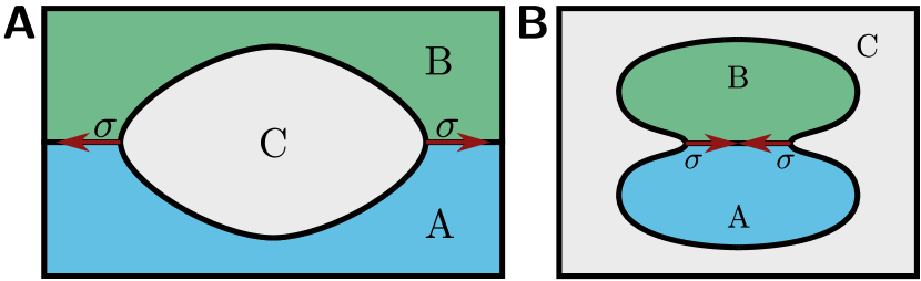
In this paper, we investigate elastic capsules at an interface between two liquid phases A and B, see Fig. 1. If the capsule adsorbs to an external liquid-liquid interface, this interface exerts a tensile line stress on the capsule as shown in Fig. 1(A). If two liquid phases A and B coexist inside the capsule, for example, after a phase separation process, the liquid-liquid interfaces exerts a contractile line tension, see Fig. 1(B). Similar systems with contractile line tensions are liquid droplets in contact with a membrane Kusumaatmaja and Lipowsky (2011), two-component vesicles after phase separation Jülicher and Lipowsky (1996), or cells during mitosis Zumdieck et al. (2007), where the tension is exerted by the contractile actin ring. We will mainly focus on capsules adsorbed to liquid interfaces exerting tensile stresses in this paper, but the corresponding shapes for contractile stresses can be obtained using the same theoretical approaches provided in this paper.
There have been various studies concerning hard particles at liquid-liquid interfaces Park et al. (2011); Park and Lee (2012) that can be extended to deformable particles resulting in an additional degree of tunability. Recently, the spreading of filled soft particles made from crosslinked gels (microgel particles) at liquid-liquid interfaces has been investigated experimentally Richtering (2012), by molecular dynamics simulations Mehrabian et al. (2016); Geisel et al. (2015), and analytically Style et al. (2015). When it comes to collective phenomena, experiments with microgel particles enclosing solid silica cores have revealed complex packing phenomena at the interface Rauh et al. (2017). Interfaces with hard particles enclosing soft shells also exhibit special elasticity with constitutive relations that change upon hard core contact Knoche and Kierfeld (2015).
Soft particles at liquid-liquid interfaces are efficient emulsifiers because they can stretch during adsorption Style et al. (2015). Adsorption to the liquid-liquid interface takes place if the liquid-liquid surface tension is sufficiently high, such that there is a net energy gain from a reduction of liquid-liquid interface area. Under these conditions, soft particles are stretched at the liquid-liquid interface and assume an energetically optimal lens-like shape Style et al. (2015); Mehrabian et al. (2016); Geisel et al. (2015), which further increases the occupied interface area at the cost of increased elastic energy. The lower this cost, i.e., the softer the particle, the greater the interface area that gets occupied, and the more the reduction in the total energy of the liquid–liquid interface by adsorbed particles.
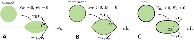
Therefore, hollow elastic capsules with a thin elastic shell, which are much softer than filled particles, are very attractive candidates to improve emulsification further. We will characterize their deformation behavior in detail in this paper and show that elastic capsules at a liquid-liquid interface take discus- or lens-like shapes due to surface tension in the interface plane, which leads to an expansion of the capsule circumference against stretching forces and bending moments in the shell, see Fig. 2. The shape of elastic capsules resembles the well-known lens-like shapes of a liquid droplet partially wetting a liquid-liquid interface as shown in Fig. 2(A). Varying the surface tension versus Young’s and bending modulus of the capsule we will systematically study the crossover from surface tension dominated droplet-like elasticity (liquid lens in Fig. 2(A)) to Hookean membrane elasticity for finite Young’s modulus but zero bending modulus (elastic lens in Fig. 2(B)) to shell elasticity with finite Young’s and bending modulus (rounded elastic lens in Fig. 2(C)).
Apart from modifying the adsorption behavior, capsule deformation by interfacial circumferential tension constitutes an independent hydrostatic method of probing the elastic properties of microcapsules. Understanding the deformation under known external loads allows for elastometry, i.e, the determination of the elastic properties of the capsule’s shell, which in turn can be used to infer information about the physics and chemistry of the shell as, for example, its state of crosslinking.
We will show that the overall shape of the deformed capsule – the height or contact angle of its lens-like shape – allows us to infer information about the Young’s modulus of the capsule shell, whereas the meridional curvature at the “tips” of the rounded lens, i.e., across interfacial plane where the tensile tension acts allows us to infer information about the bending modulus of the shell (if the surface tension of the liquid-liquid interface that is exerting the tensile stress is known). Other static non-contact elastometry methods following the same philosophy are the study of deformations of pendant capsules under volume changes to obtain elastic moduli as investigated in Refs. 32; 33; 34, the study of the edge curvature of buckled shapes to obtain the bending modulus Knoche and Kierfeld (2011), or the study of shapes of osmotically buckled capsules to infer the osmotic pressure Knoche and Kierfeld (2014a). Non-contact techniques requiring motion in the surrounding fluid are shape analysis in shear flow Chang and Olbricht (1993); de Loubens et al. (2016), in extensional flow de Loubens et al. (2014), and spinning drop rheometry Pieper et al. (1998).
The paper is structured as follows: first, we discuss relevant capillary lengths scales and introduce our elastic model for the deformation of a microcapsule of fixed volume using shape equations. The external stretching force that the liquid-liquid interface exerts on the capsule is taken into account via a Neumann triangle construction for the force equilibrium at the contact line between capsule and liquid-liquid interface. Then, we discuss numerical solutions for the resulting shapes in three elasticity regimes: the well-known droplet limit, where only surface tension acts and the capsule becomes equivalent to a droplet partially wetting the liquid-liquid interface, the membrane regime corresponding to a shell of vanishing thickness but with finite Young’s modulus, and the shell regime, where we also account for bending moments and transverse shear stress due to the shell’s finite thickness. We then discuss how to extract Young’s and bending modulus from characteristics of deformed capsule shapes based on analytical results. Finally, we use our results on capsule deformation to calculate the enhancement of the adsorption energy for hollow capsules for decreasing shell thickness.
II Methods
In the following, we introduce our model of a microcapsule as a Hookean shell. We start with the elastic model parameters, which also give rise to different capillary length scales controlling the deformation by the liquid-liquid surface tension and the relevance of gravitational effects. We introduce the geometric description for axisymmetric shells, the elastic energy, constitutive relations, and finally the shape equations, which can be used to obtain shape profiles by numerical integration. The shape equation approach has also been used in Refs. 35; 32; 36; 41; 42; 34. Therefore, we defer details to Appendix A. The deformation by a localized circumferential stretching force due to the liquid-liquid surface tension is the novel aspect in the present problem, which is taken into account by employing appropriate matching conditions at the three phase contact line with the liquid-liquid interface.
II.1 Elastic parameters and capillary length scales
The capsule is enclosed by an elastic shell of thickness whose resting shape is a sphere with radius . In the limit of a thin shell, , made from an isotropic and homogeneous elastic material with Young’s modulus , we can use an effectively two-dimensional description with a two-dimensional Young’s modulus and a bending modulus given by Libai and Simmonds (1998)
| (1) |
where is the two-dimensional Poisson ratio. Choosing as unit of length and as unit of tension, the dimensionless bending modulus is given by
| (2) |
where is the Föppl-von-Kármán number, and the last equality again assumes (cp. eq. (1)) a thin shell made from an isotropic and homogeneous elastic material. Note that we use the same units throughout the paper, i.e., we measure tensions in units of the Young’s modulus and lengths in units of the resting shape’s radius . Using these natural units we transform quantities to their dimensionless counterparts .
By fixing the Poisson ratio (corresponding to a linearly incompressible bulk material) the capsule’s elastic response to external forces is solely determined by the dimensionless bending modulus . Typical values for microcapsules range within assuming , and Hegemann et al. (2018). If (corresponding to for ) we expect to obtain (at least qualitatively) the crossover to the limit of a filled soft particle that has been considered in Refs. 27; 28; 29.
Based on Young’s modulus we can estimate the typical deformation. The capsule will be stretched by the surface tension of the liquid-liquid interface, which acts along the circumference of the capsule. A deformation by at the liquid-liquid interface causes strains and costs an elastic stretching energy but gains an interfacial energy . The resulting strain is of order , i.e., independent of capsule size but limited by shell thickness for hollow capsules. The behavior is different for a filled soft particle, where we expect , i.e., small filled particles deform stronger than large filled particles. For filled soft particles, this allows to define an elastocapillary length such that deformations by the surface tension become large for small particles Style et al. (2015); Vella (2015). For hollow capsules with a soft shell, on the other hand, deformations become large if the shell thickness is sufficiently small compared to the elastocapillary length: (or ). We can generally state that hollow capsules deform more significantly than filled soft particles of the same size.
Although the size of the capsule is not relevant for deformation by the liquid-liquid interface, it will play a role for deformation by gravitational forces. The typical gravitational energy gain upon deformation by is , where is the density difference between the liquids inside and outside the capsule. Gravitational energy competes with the elastic deformation energy resulting in strains , i.e., deformation by gravitation is relevant for capsules larger than a gravitational elastocapillary length .
Moreover, capsule size is also relevant for the deformation of the liquid-liquid interface by the gravitational force on the capsule, i.e., the shape of the meniscus. The balance of the gravitational energy and the interfacial energy shows that the meniscus is curved on the scale of the capillary length . Only capsules larger than give rise to a relevant curvature of the liquid-liquid interface Vella (2015).
We will focus on soft hollow capsules with , for which gravitational effects both for the meniscus and capsule deformation are negligible, i.e., , and strains of the capsule do not become large but are non-negligible, i.e., or . For artificial microcapsules this is a generic situation, as the following estimates show: For microcapsules with with a typical soft capsule shell material with and a shell thickness (corresponding to ), with a liquid-liquid interfacial tension (e.g. oil-water) of , and with , we find a capillary length and a gravitational elastocapillary length , which are much larger than , and an elastocapillary length , which is of the order of the thickness .
II.2 Parametrization
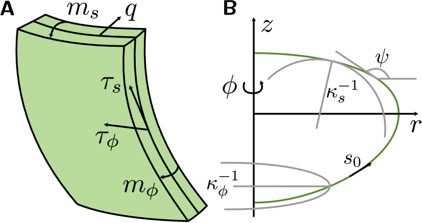
We consider the axisymmetric elastic shell as a surface of revolution around the -axis (see Fig. 7 in the Appendix for details). The shell contour (its generatrix) is given in cylindrical coordinates , where is the arc length of the undeformed shape and is the distance from the -axis. The total arc length of the contour is , i.e., . The arc length element of the deformed shape derives as , and the unit tangent vector ( being the angle between and the -axis) gives the orientation of a capsule patch relative to the axis of symmetry. The undeformed reference shape shall be given by a sphere with rest radius , i.e., , which generates (by revolution around the -axis) a sphere with radius whose lower apex (intersection with the symmetry axis) is located at and .
II.3 Elastic energy
Stretching deformations with respect to the undeformed spherical shape can be expressed in terms of the stretches and , and bending deformations in terms of the principal curvatures and , which derive from the second fundamental form of a surface of revolution Do Carmo (1994). The deformation energy is formulated best in terms of the (stretching) strains employing a small strain approximation and bending strains , where we expanded up to linear order in deviations from the undeformed reference shape with and . 111 Systematic derivations starting from thin three-dimensional elastic materials Ciarlet (2006); Efrati et al. (2009) show that factors should be contained in the definition of bending strains. As a result, a spherical shell that is uniformly stretched from radius to radius has and but vanishing , which is reasonable because it has obviously not developed bending moments but only stretching tensions. For strictly two-dimensional materials with bending energy functionals such as the Helfrich energy, the curvature cannot be changed by stretching the material. We consider hyperelastic materials, whose elastic energy can be expressed in terms of a local energy density, and use a Hookean surface energy density Libai and Simmonds (1998)
| (3) | ||||
with the linear approximation . The three terms in the energy density correspond to the three contributions from stretching, from bending, and from an effective interfacial tension between the fluids outside and inside the capsule. We consider capsules smaller than the gravitational elastocapillary length , such we can neglect gravitational body forces in the energy. We explicitly state the undeformed surface element to highlight the fact that this energy functional operates on the undeformed surface which is important for computing stresses from it.
The energy (3) explicitly contains a contribution from an isotropic effective surface tension between the outer liquids and the capsule. Such a contribution arises either as the sum of surface tensions of the liquid outside with the outer capsule surface and the liquid inside with the inner capsule surface or, if the capsule shell is porous such that there is still contact between the liquids outside and inside the capsule, with additional contributions from the surface tension between outside and inside liquids. In general, the liquid phases A in the lower half-space and B in the upper half-space will have different surface tensions and with the capsule. We will distinguish between the simpler symmetric case (which is also depicted in Fig. 2) and the general asymmetric case with . We will mainly focus on the symmetric case throughout the paper, where the AB-interface acts along the equator of the capsule.
The dimensionless surface tension (with in the symmetric case) is another important control parameter of the capsule, which governs the crossover from a liquid droplet to an elastic Hooke membrane or shell: For the capsule behaves as a liquid droplet and assumes lens-like shapes as in Fig. 2(A). For the capsule behaves either as a Hookean membrane also assuming a lens shape as in Fig. 2(B) (for small bending moduli ) or as an elastic shell assuming a rounded lens shape as in Fig. 2(C) (for larger bending moduli ).
We assume a spherical rest shape of the capsule, i.e., the capsule is not synthesized at the liquid-liquid interface but inside one of the liquid phases A or B before it is adsorbed to the interface. As already worked out in Ref. 29, adsorption of a spherical particle to the AB-interface also depends on the surface tension of the AB-interface: If the particle stays in liquid B, if the particle stays in liquid A. For sufficiently large , the particle will always adsorb to the interface.
We note that the energy functional (3) (with ) also correctly describes the low-strain behavior of more sophisticated energy functionals, e.g., of the Mooney-Rivlin type Libai and Simmonds (1998); Barthès-Biesel et al. (2002). In this regard, our model as well as the constitutive relations given below are a small strain limit. The Hookean small strain description is often sufficient and the most simple though non-trivial choice. For larger strains, Mooney-Rivlin, Skalak or other elastic energies are more appropriate. In general, we expect large strains to occur for stretching tensions () and . Tensile stresses are realistic for typical experimental situations. In Appendix A.1, we find that, for , meridional strains remain small, whereas circumferential stretching factors can become locally large, where the liquid-liquid tension acts (reaching values for , see Fig. 8 in the Appendix). We do not expect, however, that any of our results will qualitatively change if nonlinear elastic laws beyond Hookean elasticity are used in this regime. This is also what has been found for deflated pending capsule shapes in Ref. 34.
II.4 Constitutive relations
Variation of the elastic energy with respect to the strains gives the tensions ; variation with respect to the curvatures gives the bending moments . This gives the corresponding constitutive relations of the capsule material for a Hookean elastic material,
| (4) | ||||
which are nonlinear since the Cauchy stresses are defined with respect to the deformed arc length, but the surface energy density measures lengths in terms of the undeformed arc length. Note that the surface tension gives a constant and isotropic contribution to the tensions and .
II.5 Shape equations
The equilibrium shape of an infinitesimal thin shell is described by local stress equilibrium in tangential and normal direction; elastic shells of finite thickness additionally require torque (bending moment) balance (see Appendix A.1). In combination with the constitutive laws (4) and three differential equations following from cylindrical parametrization the stress and moment equilibrium lead to a closed system of six shape equations for axisymmetric Hookean shells,
| (5) | ||||
where the quantity is the transverse shear stress, is the total internal normal pressure, and is the shear pressure. Since we consider a closed microcapsule encapsulating an incompressible liquid phase, will have a hydrostatic contribution, , that has to be fixed by the volume constraint (see Appendix A.1). Throughout the paper we consider closed microcapsules containing an incompressible liquid phase. Therefore, all deformations are at fixed volume, which is given by for an elastic capsule with spherical rest shape of radius . External forces from the surface tension of the AB-interface enter via the additional normal and shear pressures and and will be discussed in the following section in detail. We consider capsules smaller than the gravitational elastocapillary length , such that we can neglect a gravitational contribution to the pressure in the last shape equation, see also section II.7 below.
The first three equations in (5) are geometric relations. The fourth and sixth equations in (5) describe the tangential and normal force equilibrium, respectively. The fifth equation is the equilibrium of bending moments. Equivalently, the fourth and fifth shape equations in (5) can be obtained by a variational approach, where we minimize the total free energy
| (6) |
with respect to the independent functions and (we repeat this calculation from Ref. 35 in Appendix A.1.1 for completeness of the presentation) and where is the potential energy for the external forces from the surface tension (see following section). The sixth shape equation in (5) is equivalent to an additional algebraic relation (see also eq. (38) in Appendix A.2), which is obtained in this variational calculation. The shape equations (5) are closed by eliminating and by using the two constitutive relations for stresses and strains from eq. (4), using the geometric relation , and eliminating and by using the two constitutive relations for bending moments and bending strains from eq. (4). This procedure is explained in detail in Ref. 35.
The shape equations in the form (5) are still independent of the elastic material law and only contain stress and moment equilibrium and geometrical relations but no information on the elastic material law, i.e., the constitutive relation. The constitutive relation is needed to close the shape equations. We use the nonlinear Hookean elasticity (4) but also other constitutive relations can be implemented. In Ref. 34 it has been explicitly shown how to use a Mooney-Rivlin relation to close the shape equations (5).
Because the six shape equations (5) are of first order, six boundary conditions are needed. Boundary conditions at the apices ( and ) are because the capsule is closed, because there are no kinks, and because there are no point loads at the apices which could cause a transverse shear stress . The boundary conditions to the remaining quantities , , and are a priori unknown, and we have to solve the shape equations (5) by a shooting method as explained in the Appendix A.3 to fulfill boundary conditions at both apices.
II.6 Matching conditions at the liquid-liquid interface
The aim of this paper is to study the deformation behavior of microcapsules during adsorption at a planar liquid-liquid interface, which can be found, for example, between two horizontally layered immiscible liquids A and B. We assume the AB-interface to be in the horizontal plane at and define the corresponding arc length by . Gravity can lead to a lowering of the adsorbed capsule, which will deform the AB-interface Vella (2015). We focus on capsules smaller than the capillary length such that this effect can be neglected. We will only briefly discuss gravity effects in more detail in the next section II.7. Neglecting gravity we have a purely horizontal stretching force from the interfacial tension from the AB-interface. We will refer to as the interface load because is responsible for stretching the capsule.
Adsorption of an object that forms a circular cross-section with the horizontal interface changes the interfacial surface energy by . From this energy we derive the force density from the interface load by variation with respect to shape changes,
| (7) |
which acts normal to the contact line of the capsule at () in horizontal direction. The force density (7) can be formally incorporated into the shape equations (5) as additional normal and shear pressure contributions and (see eq. (31) in Appendix A.1), which cannot be integrated over directly as they are singular. Instead, we can also solve (5) piecewise for and (corresponding to and ), and derive matching conditions at the three phase contact line at or to account for the force density (7).
Because the shape equations (5) are first order, the number of matching conditions has to equal the number of shape equations (5) if the interface position along the capsule is known. In the symmetric case , upper and lower part of the capsule are related by reflection symmetry. Then, the AB-interface is located at the known arc length , such that matching conditions are required. In the general asymmetric case the AB-interface, also has to be determined, such that matching conditions are required.
We first discuss the symmetric case. For a Hookean shell, we have the full set of shape equations (5). The shell becomes an elastic membrane in the limit of vanishing , i.e., vanishing bending modulus , which implies vanishing bending moments and vanishing transverse shear stress , such that only shape equations are left. A liquid droplet cannot support elastic stresses, such that , there is no reference shape, such that , and also tangential stresses can be eliminated from (5), leading to equations equivalent to the well-known Laplace-Young shape equations, see eqs. (46) in the Appendix.
In the symmetric case, we need matching conditions to fit piecewise solutions for the upper and lower half uniquely together. First, we have to impose continuity for the variables and , which ensures a closed capsule shape. In addition, we impose at the interface resulting in three matching conditions.
The remaining matching conditions are derived in the Appendix A.2 from variation of the total free energy (6). We find two matching conditions (40) and (41) corresponding to the balance of interfacial forces in - and -direction at the three phase contact line, i.e., a Neumann triangle construction Neumann (1894) (see also Fig. 2). Only force balance in -direction involves the interfacial force (7) in the absence of gravity effects. In the variational calculus the force balance equation in -direction is obtained as a Weierstrass-Erdmann condition from variation with respect to . In -direction, the interfacial forces from the upper an lower part of the capsule not only balance each other at the AB-interface in the Neumann construction, but each of them is also balanced by the pressure force because both the upper and the lower part of the capsule must be force-free in -direction in equilibrium (see eq. (39) in the Appendix). Therefore, continuity of the variable is actually equivalent to the Neumann matching condition (40) in -direction. If both conditions are used, the set of matching conditions becomes over-determined. Interestingly, using both equations in an over-determined set of matching conditions makes our numerical analysis typically more stable.
For the Hookean membrane, two continuity conditions for and , the value at the AB-interface, and the Neumann triangle condition (41) in -direction, are the required matching conditions to make the problem well-posed. For the Hookean shell we also get a continuity condition for ensuring a smooth shape without kinks (which are forbidden by bending energy) and obtain an additional moment equilibrium (42) at the contact line (as a Weierstrass-Erdmann condition from variation with respect to ) resulting in the required conditions for the Hookean shell.
In the general asymmetric case, the AB-interface is located at an arc length (), which has also to be determined from variation of the total free energy. In Appendix A.2 we find an additional transversality condition (43) by equating the boundary terms in the variational calculus. This condition is equivalent to the statement, that the discontinuity of the surface energy density originates only from the discontinuity of the surface tension with the surrounding liquid , which jumps from to at the AB-interface. This, in turn, is equivalent to requiring that the elastic contributions to the meridional tension are continuous at the AB-interface (i.e., their absolute values are continuous, their directions can be discontinuous, for example, in the Hookean membrane case in an elastic lens, see Fig. 2(B)).
II.7 Gravity
Body forces, such as gravitation and buoyancy, that act upon the capsule can bend the AB-interface Vella (2015) and can deform the capsule. We already showed that gravity leads to a curved meniscus of the AB-interface if the capsule radius is larger than the capillary length and that gravity deforms the capsule if the capsule radius is larger than the gravitational elastocapillary length . Both capillary lengths are typically of the order of millimeters, such that gravity can be neglected for microcapsules. Now we want to briefly address in more detail, how our model had to be modified in order to include all gravity effects. The involved quantities are explained in Fig. 3.
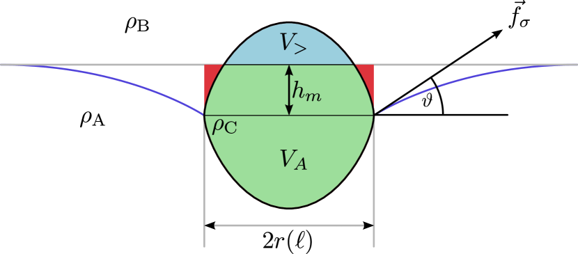
For an axisymmetric capsule the total body force containing gravitational and buoyancy force is directed in -direction. The AB-interface contacts the capsule at but if this interface bends downward we no longer have as without gravity but with a height of the meniscus (if is the position of the AB-interface at infinity, see below). One contribution to the buoyancy force is given by the weight difference of the volume (red area in Fig. 3) of the liquid A that has been displaced by liquid B vertically above the contact line and the capsule surface up to the original horizontal AB-interface at Keller (1998), where is the capsule volume above the plane (blue area in Fig. 3; if the entire capsule is below the plane). The other contribution to the buoyancy force is given by the weight difference of volumes (green area in Fig. 3) of liquid A and (blue area) of liquid B that have been displaced by the capsule interior C. Both contributions add up to
| (8) |
If and the AB-interface bends, the interface load , see eq. (7), also has a component in direction, which, integrated along the circular cross-section, exactly compensates in equilibrium,
| (9) |
This determines the angle between the interface tangent and the -axis at the three phase contact line.
If is known, the complete shape of the AB-interface follows from the Laplace equation, which can be written in the form
| (10) |
with a capillary length , which is determined by the density difference of the two liquid phases, and with the unit normal vector onto the AB-interface Finn (1986). We consider the case of equal pressures in phase A and B in eq. (10) such that the interface becomes planar at infinity; we choose the -coordinates such that the AB-interface is at at infinity.
Moreover, the shape of the capsule changes in the presence of gravity. First, gravity gives rise to a hydrostatic pressure contribution to the pressure in the last shape equation in (5), where is the density difference between the capsule interior C and the liquid phase A for (where the capsule is in contact with liquid A) and the density difference between liquid phase B and capsule interior C for (where the capsule is in contact with liquid B). Second, the matching conditions at the AB-interface have to be modified if the angle is non-zero. Then the force density acquires a non-zero -component , which enters the Neumann triangle condition in -direction, and the modified -component enters the Neumann triangle condition in -direction.
Thus, our model can be easily extended to include all gravitational effects properly if larger, millimeter-sized capsules are considered that are no longer small as compared to the capillary length or the gravitational elastocapillary length .
III Results
In the remainder of this paper, we present and discuss numerical, quantitative results from solving the shape equations for different control parameters: the dimensionless bending modulus or Föppl-von-Kármán number controlling the relevance of bending energy, the dimensionless surface tension controlling the capsule elasticity from liquid droplet to elastic capsule, and the dimensionless interface load or characterizing the strength of the deforming force from the AB-interface. We will neglect gravitational effects, i.e., consider the typical situation that microcapsules are smaller than both gravitational capillary lengths, and .

We also discuss analytical results for characteristics of the lens-like droplet or capsule shapes, where it is possible. We will show that the height or contact angle of the lens is directly related to the Young’s modulus of the capsule shell (or the surface tension of a droplet), i.e., the dimensionless parameters characterizing the tensile force exerted by the AB-interface and the dimensionless surface tension governing the crossover from a liquid droplet to an elastic Hooke membrane or shell. The maximal curvature at the “tips” of the rounded lens, allows us to infer information about the bending modulus of the shell.
Finally, we can quantify the adsorption energy gain by deformation relative to the adsorption energy gain of a hard undeformable particle, which is an important quantity for applications of capsules as surface active agents, for example, in emulsification.
In Fig. 4, we show numerically calculated evolutions of capsule shapes for varying interface loads , both for tensile () and contractile () tensions. We show these evolutions both for symmetric () and asymmetric surface tension between capsule and phases A and B and both for a Hookean membrane without bending rigidity and an elastic shell (). We clearly see the typical lens- or discus-like shapes for tensile interface loads. For contractile loads, a stable shape can only be obtained in the symmetric case, where we observe characteristic dumbbell shapes.
In the following paragraphs, we discuss aspects of the lens-like shapes under tensile interface loads quantitatively. We focus on symmetric surface tensions (shapes in the upper part of Fig. 4) and vary the dimensionless surface tension and bending modulus to cover all different surface elasticities: the well-known liquid lenses for droplets partially wetting the AB-interface (, ), elastic lenses for Hookean membranes ( finite, ), and rounded elastic lenses for microcapsules with Hookean shell elasticity ( finite, ).
III.1 Droplets and membranes: lenticular shapes
In the droplet regime (vanishing elastic moduli and ), the correct shape is found from the Laplace-Young equation, according to which the shape is assembled from spherical caps (shapes of constant mean curvature). For spherical caps the contact angle (between the tangent to the surface and the horizontal liquid-liquid interface) is related to their radius and height by
| (11) |
Dimensionless lengths denoted with a tilde are measured in units of . The dimensionless height of the spherical cap is its maximal distance from the circular base of the cap. For incompressible liquids as investigated in this paper the radius is related to the height of the spherical cap by the volume constraint (see eq. (53) in the Appendix), which gives the last equality in eq. (11). Balancing tensions at the three phase contact point, according to the Neumann triangle condition (41) for force balance in -direction, , we finally find that the height is given by
| (12) |
for the liquid lens (see also eq. (54) and its derivation in the Appendix). For increasing the dimensionless interface load , the height of the liquid lens decreases until we reach the transition to complete wetting for , where and the liquid lens becomes an (infinitely thin) wetting film.
For elastic membranes with vanishing , but finite , the presence of additional elastic stresses makes the Laplace-Young equation inapplicable. However, it is intuitively clear that adding a thin elastic membrane onto a droplet should not affect its shape drastically, such that the elastic lens should consist of approximate spherical caps as well. This is corroborated by our numerically calculated shapes in Fig. 4 (left), which appear to be similar to liquid lens shapes composed of two spherical caps. We will exploit this similarity for an analytical approximation.
A closer inspection (see Appendix C.2) reveals that strictly spherical caps with hemispherical rest shape do not allow for local force balance over the complete surface. However, we find an approximation analogous to the droplet by assuming uniform (but anisotropic) strains along the contour. Geometrically, these strains are found to be
| (13) |
Inserting these approximative strains in the constitutive relations (4) we obtain the stress as a function of . Using the Neumann condition (41) for force balance in -direction, we then find (see Appendix C.2)
| (14) |
where is given by the geometric relation (11). Similarly to (12), solving this equation for gives the reduced height and, thus, also the contact angle as a function of and .
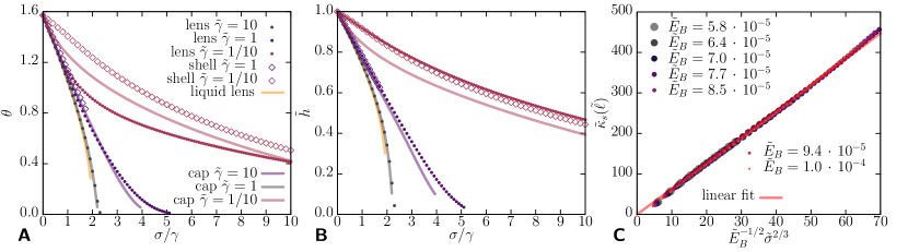
We compare our analytical results for height and opening angle to numerical solutions of the shape equations (5) in Fig. 5(A,B). The result (12) for the height of liquid lenses is in good agreement with solutions for elastic membrane lenses in the corresponding limit . Solutions of (14) for the height are in good agreement with numerical simulations within the range of the fluid and the crossover regime, i.e., for . Even for we find acceptable agreement. Note that only the dimensionless height can directly be determined for elastic shells, since the shape is rounded at the AB-interface. The solutions we obtain from (14) violate, however, the force balance condition, which explicitly demonstrates that already a simple Hookean stretching energy leads to non-trivial shapes.
III.2 Elastic shells: interface curvature
Microcapsules with elastic shells, i.e., in the presence of an additional bending rigidity, exhibit lens-like shapes with rounded kinks at the AB-interface.
For decreasing bending moduli the rounded kink at the AB-interface becomes increasingly sharp and approaches the elastic lens shape suggesting a systematic relation between the interface curvature and the bending modulus which might allow for inferring the bending modulus from the shape profile. We quantify this in Fig. 5(C) showing the curvature at the liquid-liquid interface as a function of , where we clearly find a linear relationship implying in the elastic regime . This scaling can be rationalized by an argument, which is similar to the Pogorelov theory for the rounding of the rim of a buckled elastic spherical shell be bending rigidity Pogorelov (1988); Landau and Lifschitz (1970). Details of this argument can be found in Appendix C.3. The essential idea is to consider the rounding of the sharp cusp present for an elastic lens with contact or opening angle and a complementary angle , after introduction of a finite bending rigidity. Thus, we only have to consider the deviation from the rather simple elastic lens shape on a typical length scale that is found from balancing stretching and bending contributions, from which we find the indicated scaling of the curvature . The change in the bending energy scales as whereas the interfacial contribution scales as , where is the radius of the interface cross-section. Balancing both energies leads to or , which already proves , but still depends on the angle . The scaling of is obtained from the Neumann condition (14), , and depends on whether the surface tensions (fluid regime, ) or the Young’s modulus (elastic regime, ) constitute the dominant stretching force. This results in the final result for the curvature scaling,
| (15) |
which is in full agreement with the numerical results in Fig. 5(C). Note that the dependence on the bending modulus, is universal, i.e., independent of whether we are in the fluid or elastic regime. Switching from to a finite leads to a finite and, thus, rounded edges.
Figs. 5(A) and (B) show that the analytical result (14) for the capsule height and the effective opening angle, which is obtained via the geometrical relation for spherical caps, remain a good approximation also for microcapsules with elastic shells for small dimensionless bending rigidities ( in Figs. 5(A) and (B)). This is also evident from Fig. 4, where shell and lens heights differ only slightly. Therefore, the parameters and can be inferred from measurements of capsule heights over a wide range of elastic parameters by fitting with eq. (14) for the measured capsules heights.
Our result (15) for the curvature radius at the rounded tip of an elastic shell then also suggests that the classical Neumann condition for symmetric liquid droplets, , still holds for elastic shells and lenses as long as the curvature radius at the rounded tip is small compared to the radius of the capsule, i.e., for (in the elastic regime ), if the approximative uniform stress is used as capsule-liquid surface tension , and if the effective Neumann angle is used for . Similar observations have been made for the shapes of adhered vesicles Seifert and Lipowsky (1990), which are also governed by the Young equation for liquid droplets with en effective surface tension as long as the contact curvature radius is small compared to the vesicle size. In Fig. 5(B), where (quads) and where we focus on the elastic regime and , the condition of small curvature radii is already fulfilled for and , respectively.
III.3 Adsorption energy enhancement
Soft particles at liquid-liquid interfaces are efficient emulsifiers because they stretch during adsorption Style et al. (2015). During deformation at the liquid-liquid interface a soft particle assumes a lens-like shape Mehrabian et al. (2016); Geisel et al. (2015), which increases the occupied interface area and, thus, decreases the interfacial energy, while the elastic energy increases. Typically, the elastic energy cost is smaller than the energy gain due to spreading within the interface, meaning that spreading is energetically preferable. The higher the interfacial energy gain compared to the elastic cost (integrated energy density ), the more stable the interface becomes. The sum of the above two contributions is what we refer to as the adsorption energy. In Ref. 54 the adsorption stability of nanoparticles at liquid-liquid interfaces has been investigated as a function of the particle shape, where it turns out that oblate shapes are most stable due to the high area occupation within the interface. Therefore, hollow elastic capsules with a thin elastic shell, which are much softer than filled particles, are very attractive candidates to improve emulsification further.
Using our numerical results we can quantify the increase in adsorption energy as a function of the softness of the capsule. The adsorption energy of a deformable capsule is given by the total energy gain if the capsule is moved from one of the liquid phase to the liquid-liquid interface,
| (16) |
where is the occupied circular cross-section area within the liquid-liquid interface plane and the last term is the elastic energy including stretching energy, bending energy, and the change in surface energy . Each capsule moving to the liquid-liquid interface lowers the interfacial energy by and, thus, decreases the effective surface tension of the liquid-liquid interface.
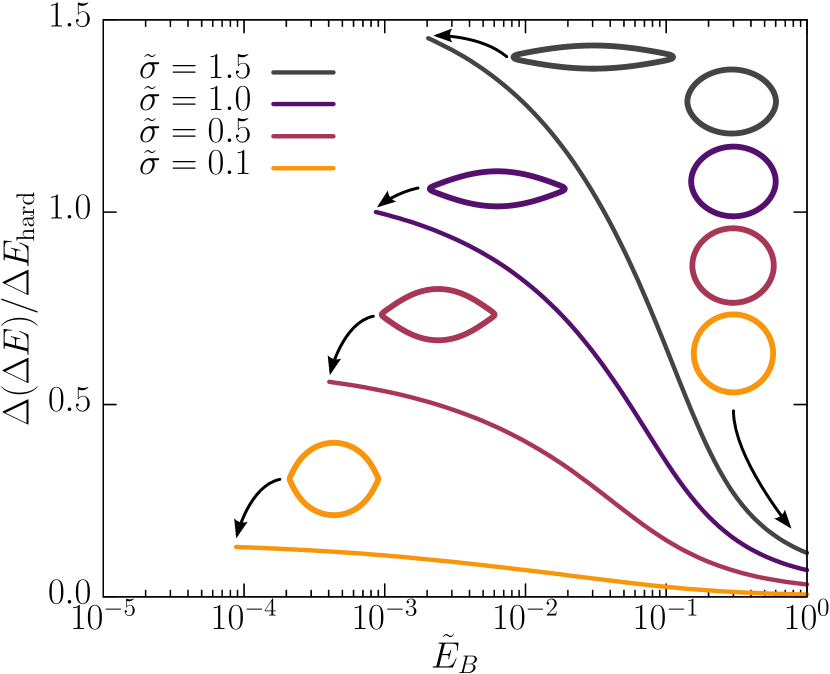
This effect is stronger for hollow soft elastic capsules as compared to hard particles and becomes more pronounced with decreasing thickness of the capsule. For hard spherical particles of equal size we have an adsorption energy . In Fig. 6 we numerically quantify the adsorption energy difference between soft and hard particles,
| (17) |
as a function of the dimensionless bending modulus , which characterizes the thickness of the capsule, see eq. (2). This allows us to quantify the relative enhancement of the adsorption energy due to capsule softness by decreasing or the capsule thickness. For (corresponding to and ) the results should become similar to the energy gain for soft filled particles as they have been considered in Refs. 27; 28; 29. Fig. 6 then clearly shows that hollow capsules are much more efficient as emulsifiers than filled soft particles (or even a filled hard particle) of equal size.
IV Discussion and conclusion
We investigated shapes of deformed microcapsules adsorbed at liquid-liquid interfaces. We mainly focused on the situation where capsules are stretched by a liquid-liquid interface outside the capsule, see Fig. 1(A) but our numerical methods (including matching conditions) are equally applicable to compressive tension, which arise, if a liquid-liquid interface is formed inside the capsule, see Fig. 1(B). We demonstrated this in Fig. 4, where we present numerical results for both cases.
Gravitational effects can be generically neglected for micrometer-sized capsules because both the capillary length and the gravitational elastocapillary length are in the millimeter range exceeding capsule size. We showed in section II.7, how our model can be extended to include all gravitational effects if larger, millimeter-sized capsules are considered in future work.
The deformability of hollow microcapsules by the liquid-liquid interfacial tension mainly depends on their thickness . For hollow capsules with a soft shell strains become large if , i.e., if shell thickness is sufficiently small compared to the elastocapillary length . For a typical soft capsule shell material with , liquid-liquid interfacial tensions are sufficient to induce considerable (but not large) strains, which can be realized by oil-water interfaces.
Shapes of deformed capsules with spherical rest shapes are lens-like if they are stretched at a liquid-liquid interface; in the presence of bending rigidity the edge of the lenticular shape is rounded. Neglecting gravitation we derived shape equations and matching conditions at the liquid-liquid interface for the numerical calculation of these shapes for extensible shells of finite thickness and constant volume, as well as for two important limiting cases, namely elastic lenses (zero bending modulus) and liquid lenses (zero Young’s and bending modulus, only surface tension). We calculated numerical solutions for each of these cases, see Fig. 4. We also derived analytical approximations for characteristics of the deformed capsule shapes in agreement with our numerical results.
Our approximative theory based on spherical cap shapes can be used to determine Young’s modulus and the pressure from a single measurement of the cap height or the contact angle , if the surface tensions and are known, see Fig. 5(A,B). Two height measurements of the same capsule at different surface tensions or at different capsule volumes could be used to determine both Young’s modulus and the capsule-liquid surface tension (assuming values for the Poisson ratio, for example, ).
This could be further extended, and our scheme for numerical calculation of shapes can, in principle, be used for elastometry, i.e., to determine elastic moduli from an experimentally acquired image by fitting numerical solutions of the shape equations to a set of contour points extracted from the image. Other elastometry methods following the same philosophy are the study of deformations of pendant capsules under volume changes to obtain elastic moduli as investigated in Refs. 32; 33; 34, the study of the edge curvature of a buckled shapes to obtain the bending modulus Knoche and Kierfeld (2011), or the study of shapes of osmotically buckled capsules to infer the osmotic pressure Knoche and Kierfeld (2014a).
For shells of finite thickness we also found an analytical result for the maximal curvature at the “tips” of the rounded lens in terms of the bending modulus, Young’s modulus and the interface load, see eq. (15) and Fig. 5(B). Also this analytical result can be used in several ways to extract information on elastic moduli from a measurement of the shell’s curvature at the interface and if the interface load from the liquid-liquid surface tension is known. If Young’s modulus of the capsule material is known (for example, from other elastometry methods Knoche et al. (2013); Nagel et al. (2017); Hegemann et al. (2018)) we can determine the bending modulus by
| (18) |
If the shell thickness is known we can determine bending modulus or Young’s modulus by
| (19) | ||||
where we used . The numerical prefactors in eqs. (18) and (19) were determined by a linear fit to the numerical results and we used relation (1) for and . Note that , which is why it makes sense to vary the interface load in order to improve the statistical significance of such a measurement. This could be achieved by, e.g., adding surfactants to one of the liquid phases or that decrease with increasing surfactant concentration. The dependence of and the surfactant concentration can be determined, e.g., in a pendant drop tensiometer. The curvature can be obtained from analyzing capsule images and fitting a circle to the capsule edge at the liquid-liquid interface. Using typical values for soft microcapsules (, corresponding to ) and a liquid-liquid interfacial tension (e.g. oil-water) of , we expect curvature radii according to (18), which can be measured optically as has been demonstrated in Ref. 55.
In conclusion, the results presented in this paper allow us, in principle, to determine the full set of elastic constants from shape profiles of elastic capsules adsorbed to liquid-liquid interfaces. To realize this setup experimentally, several problems have to be solved. One main problem will be to find a liquid-liquid interface with sufficiently high surface tension such that the condition for adsorption of the capsule to the interface is fulfilled and such that the observed strains and, thus, the capsule deformation are observable. Another problem might be leakage through the capsule membrane, while we assume a fixed volume in the present calculation. A known shrinking volume can, however, be included in the present approach by introducing a corresponding decreasing internal pressure .
Finally, we could show that hollow elastic microcapsules can be much more effective in reducing the interfacial energy than filled soft particles or even hard particles of the same size, see Fig. 6. During capsule deformation at the liquid-liquid interface into a lens-like shape the adsorption energy, which results from the balance of the occupied liquid-liquid interface area and the elastic energy of the capsules shell, increases significantly. In Fig. 6 we compare hollow capsules, filled soft particles and hard particles of equal size . The effectiveness of hollow capsules in reducing the interfacial energy can also be appreciated by comparing with particles of equal deformability: A hollow capsule with shell thickness exhibits a similar elastic deformation as a filled soft particle of size . The size of the hollow microcapsule can be made much larger, however, in order to achieve a much larger occupied liquid-liquid interface area as compared to the filled particle. This leads to much higher adsorption energies at comparable softness. We conclude that hollow microcapsules could be much more efficient in foam and emulsion stabilization than filled particles of comparable size or comparable softness.
Conflict of interest
There are no conflicts to declare.
Acknowledgements
We acknowledge financial support by the Deutsche Forschungsgemeinschaft via SPP 1726 “Microswimmers” (KI 662/7-1).
References
- Vert et al. (2012) M. Vert, K.-H. Hellwich, M. Hess, P. Hodge, P. Kubisa, M. Rinaudo, F. Schué, et al., Pure Appl. Chem. 84, 377 (2012).
- Dinsmore et al. (2002) A. Dinsmore, M. F. Hsu, M. Nikolaides, M. Marquez, A. Bausch, and D. Weitz, Science 298, 1006 (2002).
- Donath et al. (1998) E. Donath, G. B. Sukhorukov, F. Caruso, S. A. Davis, and H. Möhwald, Ang. Chem. Int. Ed. 37, 2201 (1998).
- De Cock et al. (2010) L. J. De Cock, S. De Koker, B. G. De Geest, J. Grooten, C. Vervaet, J. P. Remon, G. B. Sukhorukov, and M. N. Antipina, Angew. Chem. Int. Ed. 49, 6954 (2010).
- Orive et al. (2004) G. Orive, R. M. Hernández, A. R. Gascón, R. Calafiore, T. M. S. Chang, P. de Vos, G. Hortelano, D. Hunkeler, I. Lacík, and J. L. Pedraz, TRENDS Biotechnol. 22, 87 (2004).
- Cook et al. (2012) M. T. Cook, G. Tzortzis, D. Charalampopoulos, and V. V. Khutoryanskiy, J. Control. Release 162, 56 (2012).
- Mondal (2008) S. Mondal, Appl. Therm. Eng. 28, 1536 (2008).
- Martins et al. (2014) I. M. Martins, M. F. Barreiro, M. Coelho, and A. E. Rodrigues, Chem. Eng. J. 245, 191 (2014).
- Aïssa et al. (2012) B. Aïssa, D. Therriault, E. Haddad, and W. Jamroz, Adv. Mater. Sci. Eng. 2012, Article ID 854203 (2012).
- White et al. (2001) S. R. White, N. Sottos, P. Geubelle, J. Moore, M. Kessler, S. Sriram, E. Brown, and S. Viswanathan, Nature 409, 794 (2001).
- Gharsallaoui et al. (2007) A. Gharsallaoui, G. Roudaut, O. Chambin, A. Voilley, and R. Saurel, Food Res Int. 40, 1107 (2007).
- Buenemann and Lenz (2008) M. Buenemann and P. Lenz, Phys. Rev. E 78, 051924 (2008).
- Yow and Routh (2006) H. N. Yow and A. F. Routh, Soft Matter 2, 940 (2006).
- Thompson et al. (2015) K. L. Thompson, M. Williams, and S. P. Armes, J. Colloid Interface Sci. 447, 217 (2015).
- Rehage et al. (2002) H. Rehage, M. Husmann, and A. Walter, Rheol. Acta 41, 292 (2002).
- Vaccari et al. (2015) L. Vaccari, D. B. Allan, N. Sharifi-Mood, A. R. Singh, R. L. Leheny, and K. J. Stebe, Soft Matter 11, 6062 (2015).
- Xie et al. (2017) K. Xie, C. de Loubens, F. Dubreuil, D. Z. Gunes, M. Jaeger, and M. Léonetti, Soft Matter 13, 6208 (2017).
- Hu et al. (2009) J. Hu, H.-Q. Chen, and Z. Zhang, Mater. Chem. Phys. 118, 63 (2009).
- Vinogradova et al. (2006) O. I. Vinogradova, O. V. Lebedeva, and B.-S. Kim, Annu. Rev. Mater. Res. 36, 143 (2006).
- Neubauer et al. (2014) M. P. Neubauer, M. Poehlmann, and A. Fery, Adv. Colloid Interface Sci. 207, 65 (2014).
- Kusumaatmaja and Lipowsky (2011) H. Kusumaatmaja and R. Lipowsky, Soft Matter 7, 6914 (2011).
- Jülicher and Lipowsky (1996) F. Jülicher and R. Lipowsky, Phys. Rev. E 53, 2670 (1996).
- Zumdieck et al. (2007) A. Zumdieck, K. Kruse, H. Bringmann, A. A. Hyman, and F. Jülicher, PloS one 2, e0000696 (2007).
- Park et al. (2011) B. J. Park, T. Brugarolas, and D. Lee, Soft Matter 7, 6413 (2011).
- Park and Lee (2012) B. J. Park and D. Lee, Soft Matter 8, 7690 (2012).
- Richtering (2012) W. Richtering, Langmuir 28, 17218 (2012).
- Mehrabian et al. (2016) H. Mehrabian, J. Harting, and J. H. Snoeijer, Soft Matter 12, 1062 (2016).
- Geisel et al. (2015) K. Geisel, A. A. Rudov, I. I. Potemkin, and W. Richtering, Langmuir 31, 13145 (2015).
- Style et al. (2015) R. W. Style, L. Isa, and E. R. Dufresne, Soft Matter 11, 7412 (2015).
- Rauh et al. (2017) A. Rauh, M. Rey, L. Barbera, M. Zanini, M. Karg, and L. Isa, Soft Matter 13, 158 (2017).
- Knoche and Kierfeld (2015) S. Knoche and J. Kierfeld, Langmuir 31, 5364 (2015).
- Knoche et al. (2013) S. Knoche, D. Vella, E. Aumaitre, P. Degen, H. Rehage, P. Cicuta, and J. Kierfeld, Langmuir 29, 12463 (2013).
- Nagel et al. (2017) M. Nagel, T. A. Tervoort, and J. Vermant, Adv. Colloid Interface Sci. , 1 (2017).
- Hegemann et al. (2018) J. Hegemann, S. Knoche, S. Egger, M. Kott, S. Demand, A. Unverfehrt, H. Rehage, and J. Kierfeld, J. Colloid Interface Sci. 513, 549 (2018).
- Knoche and Kierfeld (2011) S. Knoche and J. Kierfeld, Phys. Rev. E 84, 046608 (2011).
- Knoche and Kierfeld (2014a) S. Knoche and J. Kierfeld, Soft Matter 10, 8358 (2014a).
- Chang and Olbricht (1993) K. S. Chang and W. L. Olbricht, J. Fluid Mech. 250, 609 (1993).
- de Loubens et al. (2016) C. de Loubens, J. Deschamps, F. Edwards-Levy, and M. Leonetti, J. Fluid Mech. 789, 750 (2016).
- de Loubens et al. (2014) C. de Loubens, J. Deschamps, M. Georgelin, A. Charrier, F. Edwards-Levy, and M. Leonetti, Soft Matter 10, 4561 (2014).
- Pieper et al. (1998) G. Pieper, H. Rehage, and D. Barthès-Biesel, J. Colloid Interface Sci. 202, 293 (1998).
- Boltz and Kierfeld (2015) H.-H. Boltz and J. Kierfeld, Phys. Rev. E 92, 033003 (2015).
- Boltz and Kierfeld (2016) H.-H. Boltz and J. Kierfeld, Eur. Phys. J. Special Topics 225, 2269 (2016).
- Libai and Simmonds (1998) A. Libai and J. G. Simmonds, The Nonlinear Theory of Elastic Shells (Cambridge University Press, 1998).
- Vella (2015) D. Vella, Annu. Rev. Fluid Mech. 47, 115 (2015).
- Do Carmo (1994) M. P. Do Carmo, in Differential Forms and Applications (Springer, 1994) pp. 77–98.
- Note (1) Systematic derivations starting from thin three-dimensional elastic materials Ciarlet (2006); Efrati et al. (2009) show that factors should be contained in the definition of bending strains. As a result, a spherical shell that is uniformly stretched from radius to radius has and but vanishing , which is reasonable because it has obviously not developed bending moments but only stretching tensions. For strictly two-dimensional materials with bending energy functionals such as the Helfrich energy, the curvature cannot be changed by stretching the material.
- Barthès-Biesel et al. (2002) D. Barthès-Biesel, A. Diaz, and E. Dhenin, J. Fluid Mech. 460, 211 (2002).
- Neumann (1894) F. E. Neumann, Vorlesungen über mathematische Physik: Vorlesungen über die Theorie der Capillarität, Vol. 7 (BG Teubner, 1894).
- Keller (1998) J. B. Keller, Phys. Fluids 10, 3009 (1998).
- Finn (1986) R. Finn, Equilibrium Capillary Surfaces (Springer, 1986).
- Pogorelov (1988) A. V. Pogorelov, Bendings of surfaces and stability of shells, Vol. 72 (American Mathematical Soc., 1988).
- Landau and Lifschitz (1970) L. D. Landau and E. M. Lifschitz, Theory of Elasticity (Pergamon Press, Oxford, 1970).
- Seifert and Lipowsky (1990) U. Seifert and R. Lipowsky, Phys. Rev. A 42, 4768 (1990).
- Bresme and Oettel (2007) F. Bresme and M. Oettel, J. Phys.: Condens. Matter 19, 413101 (2007).
- Jose et al. (2014) J. Jose, M. Kamp, A. van Blaaderen, and A. Imhof, Langmuir 30, 2385 (2014).
- Ciarlet (2006) P. Ciarlet, An Introduction to Differential Geometry with Applications to Elasticity, Available online (Springer Netherlands, 2006).
- Efrati et al. (2009) E. Efrati, E. Sharon, and R. Kupferman, J. Mech. Phys. Solids 57, 762 (2009).
- Princen (1963) H. M. Princen, J. Colloid Sci. 18, 178 (1963).
- Widom (1995) B. Widom, J. Phys. Chem. 99, 2803 (1995).
- Blecua et al. (2006) P. Blecua, R. Lipowsky, and J. Kierfeld, Langmuir 22, 11041 (2006).
- Knoche and Kierfeld (2014b) S. Knoche and J. Kierfeld, EPL 106, 24004 (2014b).
- Knoche and Kierfeld (2014c) S. Knoche and J. Kierfeld, Eur. Phys. J. E 37, 62 (2014c).
Appendix A Shape equation approach
In this section, we give details on the derivation of the shape equations (5) by variational energy minimization. We give a detailed derivation of the matching conditions at the liquid-liquid interface and present details on the numerical solution of the shape equations.
A.1 Shape equations
A.1.1 Variational approach
We calculate the first variation and the resulting Euler-Lagrange equations for the free energy functional (6) by variation with respect to the functions and . First we perform the variation of
| (20) |
in the absence of the interface load (we repeat this calculation from Appendix A in Ref. 35 for completeness of the presentation), in order to derive the shape equations for the upper and lower part of the capsule. In Appendix A.2 we include to derive the matching conditions at the three phase contact line joining upper and lower part of the capsule. Assuming an incompressible liquid within the capsule and an impermeable membrane leads to conservation of the capsule volume
| (21) |
where is the radius of the spherical equilibrium shape of the capsule. The volume constraint is included by adjusting the hydrostatic pressure as a Lagrange parameter.
Using the definition of the stresses and bending moments (see first equalities in eqs. (4); in the following, ) for the variation of the elastic energy density,
| (22) |
and
| (23) |
for the variation of the volume, we find the first variation of the free energy
or
| (24) | ||||
| (25) |
where we also defined
| (26) |
Partial integration in eq. (24) gives two standard Euler-Lagrange equations
| (27) |
on the interval . Using and the geometric relations and , which follow from the definition of the slope angle (see Fig. 7(B)), these Euler-Lagrange equations can be re-arranged to give
| (28) | ||||
which represents (i) stress equilibrium in tangential direction and (ii) torque (bending moment) balance Knoche and Kierfeld (2011); Libai and Simmonds (1998) that has to hold for any interface patch, see Fig. 7(A). Moreover, the definition (26) of the normal transverse shear force density can be used to derive (together with (i)) the normal stress equilibrium Knoche and Kierfeld (2011); Libai and Simmonds (1998)
| (29) |
In order to obtain a closed set of shape equations, we also use the geometric relations
| (30) | ||||
(see Fig. 7(B)). Using to relate deformed to undeformed arc length, eqs. (28), (29), and (30) are equivalent to the shape equations (5) in the main text. To convert these shape equation system into actual geometric shapes constitutive relations are needed, which we address in the following part. Additional external shear and normal pressures (see A.1.3 below) and , respectively, can be included as additional contributions on the right hand side of the tangential stress equilibrium (i) and on the right hand side of the normal stress equilibrium (iii). Instead we will include in the free energy and derive matching conditions from the variational calculus in Appendix A.2.
A.1.2 Hookean elasticity and alternative constitutive relations
The shape equations in the form (5) are still independent of the elastic material law. They only contain stress and moment equilibria and geometrical relations and no information on the constitutive relation characterizing the material. The constitutive relations are needed to close the shape equations as described in the main text. We use a nonlinear Hookean elasticity with constitutive equations (4), which derive from the Hookean elastic energy (3).
For large stretching tensions such that () and , the stretching strains are no longer small and the linear approximation breaks down. Then the essentially linear Hookean constitutive relation (4) is no longer valid and has to be replaced by more specific nonlinear hyperelastic material laws, such as Mooney-Rivlin or Skalak laws Libai and Simmonds (1998); Barthès-Biesel et al. (2002). For the Mooney-Rivlin law it has been explicitly demonstrated in Ref. 34 how this constitutive relation can be used to close the shape equations (5). Because the shape equations (5) are closed by eliminating and by using the constitutive relations for stresses and strains, nonlinear relations such as Mooney-Rivlin laws are considerably more difficult to handle and lead to a larger computational cost Hegemann et al. (2018).

In Fig. 8, we investigate in more detail whether nonlinear effects can play a role for capsules stretched with tensile stresses , which are realistic for typical experimental situations and also used for the shape evolutions in Fig. 4. We find that meridional strains remain small, whereas circumferential stresses can indeed become large locally in the vicinity of the liquid-liquid interface (reaching values for ). This will lead to a further stretching of the capsule shape if, for example, a more realistic Mooney-Rivlin elastic law is used which displays a softening for large strains Barthès-Biesel et al. (2002). We do not expect, however, that any of our results will qualitatively change if more realistic nonlinear elastic laws are used in this regime.
Another problem arises if compressive stresses or occur, which can give rise to wrinkle formation and require a different effective constitutive relation in the compressed region Knoche et al. (2013); Hegemann et al. (2018). We have checked explicity that such compressive stresses do not occur for capsules stretched at a liquid-liquid interface, i.e., . For compressive tensions , compressive stresses can indeed occur, such that wrinkles in -direction could form in the vicinity of the AB-interface. We do not include wrinkle formation in our analysis as we focus on tensile stresses throughout this paper.
A.1.3 Pressure and external forces
Assuming an incompressible liquid within the capsule and an impermeable membrane leads to conservation of the capsule volume (21). The volume constraint is satisfied by adjusting the hydrostatic pressure , which serves as a Lagrange parameter. In practice, the volume constraint is realized by including it in the shooting method, i.e., by using as shooting parameter to obtain a given volume at the end of the integration along the contour.
If is not interpreted as Lagrange parameter we have actual pressure control. Then the pressure is prescribed and determines the capsule volume . Solutions for pressurized capsules are numerically simpler to obtain and possibly exhibit more diverse shapes due to the lacking volume constraint. Another possibility, which is intermediate between pure pressure and pure volume control, is osmotic pressure control Knoche and Kierfeld (2014a). Then the osmotic pressure inside the capsule becomes a function of the capsule volume , the shape of which depends on the osmolyte concentration. We restrict ourselves here to capsules with a constant volume in which the hydrostatic pressure adapts accordingly.
External forces arises from the surface tension of the AB-interface which acts along the contact line at arc length around the capsule. This can be interpreted as a point load on the capsule contour, i.e., a localized force density (7).
The force density could be included as a pressure contribution into the shape equations (5) leading to normal and tangential pressure contributions
| (31) | ||||
The total normal pressure is then given by . We will rather include the point loads by deriving adequate matching conditions for the forces and at or from variation of the energy (6) in the following section A.2.
A.2 Matching conditions at the liquid-liquid interface
At the liquid-liquid interface at and the shape equations (5) have to be complemented by matching conditions. We argued in the main text that six matching conditions are needed for a Hookean shell, whose shape is obtained by the full set (5) of six shape equations, whereas only four matching conditions are needed for a Hookean membrane, which is described by four shape equations ( and in eqs. (5)). Moreover, we need to determine the parameter itself by energy minimization in the general asymmetric case. For the symmetric case we have by symmetry. The capsule consists of two solution branches and , for which we will use superscripts and , respectively, in the following to formulate the matching conditions.
We will derive all matching conditions from continuity conditions for intact closed shells and variation of the energy (6) with respect to the position of the three phase contact line at and .
We have three obvious matching conditions for and ,
| (32) |
from requiring a closed capsule. The two matching conditions for fix the shooting parameters and . From continuity of also the continuity of follows immediately. For a shell with bending rigidity we also have the fourth matching condition
| (33) |
because a kink in the capsule shell costs an infinite bending energy. Membranes and droplets, however, will exhibit such kinks and and can freely adjust. From continuity of and , also the continuity of the curvature follows.
All remaining matching conditions are derived based on the variational calculus introduced in Ref. 35 by minimizing the total free energy or (using eq. (21))
| (34) |
where are the Hookean energy densities (3) of the upper and lower parts of the capsule, which have identical elastic constants , , and but differ in their surface tension contributions with in the lower () and in the upper () part; the energy is the potential for the point force from eq. (7). The free energy has to be extremized with respect to the functions and as well as with respect to the location of the liquid-liquid interface. The total variations and at the variable interface position have to fulfill the continuity conditions and, for a shell, .
Extremizing with respect to the functions and leads to the same Euler-Lagrange equations (27) or (28), which hold both for the upper (+) and lower (-) parts. In variational calculus with variable functions at the boundary at , each continuity condition at the boundary entails a corresponding Weierstrass-Erdmann condition. Equating all boundary terms in the variation to zero we obtain the Weierstrass-Erdmann condition for
| (35) |
Likewise, equating all boundary terms in the variation to zero for shells, we find the Weierstrass-Erdmann condition for
| (36) |
Moreover, because of the variable interface position we also have to equate all boundary terms in the variation to zero (at constant volume), which gives an additional transversality condition
| (37) |
where the -terms are only present for shells.
As derived above in eq. (26), variation of gives the additional algebraic relation
| (38) |
for , which can replace the shape equation for in (5). This algebraic equation is equivalent to force equilibrium in -direction for any part of the capsule from the lower apex up to arc length . In equilibrium, the total force in axial -direction that is acting on the lower part of the capsule from the lower apex up to arc length vanishes because of axial symmetry and the absence of external forces such as gravity acting in -direction Boltz and Kierfeld (2015, 2016),
| (39) |
where we used eq. (31) for and to obtain the last equality. The first term is the total interfacial force in -direction integrated along the rim of length , the second part the total pressure force acting on the area of the lower capsule part in -direction. There are no additional forces in -direction from the liquid-liquid interface such that both contributions must cancel for all , also at the liquid-liquid interface at .
Equation (38) also implies that at the apices where and or , which justifies the boundary conditions . At the interface at the right hand side of eq. (38) is continuous because is continuous, such that
| (40) |
This is equivalent to , which holds because the liquid-liquid interface exerts no force in -direction. The first equality in eq. (40) describes a force equilibrium in the -direction at the contact line between capsule and liquid interfacial tensions and, thus, follows from a Neumann triangle construction (see also Fig. 2). The liquid-liquid interface is not exerting interfacial forces in the -direction and, thus, does not enter eq. (40); discontinuities in the normal shear force density and in the tangential force density have to cancel in -direction.
The second equality in eq. (40) shows that the continuity of is actually equivalent to the Neumann tension force equilibrium in -direction at the contact line because continuity of leads to continuity of the pressure force in -direction and interfacial and pressure forces are always opposite and equal according to the relation for the total force. Therefore, using both matching conditions (40) and always leads to an over-determined set of matching conditions.
Using the definitions (25) in the Weierstrass-Erdmann condition (35) from the variation at the boundary gives
| (41) |
which describes the force equilibrium in the radial direction at the contact line between capsule and liquid interfacial tensions and, thus, also follows from the Neumann triangle construction (see also Fig. 2). Discontinuities in the normal shear force density and in the tangential force density in -direction have to cancel with the tension , which also acts in -direction.
Likewise, using the definitions (25) in the Weierstrass-Erdmann condition (36) from the variation at the boundary gives
| (42) |
which holds for shells and describes the moment equilibrium at the contact line. Continuity of and (see above) also entails continuity of and and, thus, of the entire bending energy density.
Inserting the definitions (25) in the transversality condition (37) and also utilizing the continuity of (and and for shells) and the first equation from the force equilibrium in the -direction eq. (40) finally we find
| (43) |
Because the bending energy part of is continuous, it follows that the discontinuity in across the interface is exactly due to the discontinuity in , which jumps from for to for . This means, in turn, that the stretching elasticity part of is also continuous. Because is continuous (see above), also is continuous and, thus, the transversality condition (43) means that the elastic parts of the tensions and have to be continuous across the interface,
| (44) |
In our numerical treatment, we will not employ the transversality condition in the forms (43) or (44) but prefer to numerically minimize the total energy with respect to (changing the interface arc length for this minimization requires a re-meshing in the multiple shooting method that is explained in the next section).
A.3 Numerical method/precision
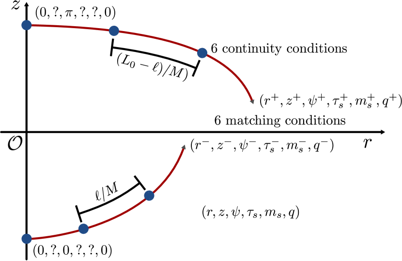
To achieve numerical stability we employ a multiple shooting method (Fig. 9), where we subdivide each solution branch in segments. At each intermediate point we gain six shooting parameters and six continuity conditions (for the general shell case). The -branch is integrated counter-clockwise over the interval starting at and ending at , the -branch is integrated clockwise over starting at and ending at . Both branches thus start at the axis of rotation and match at the interface. When the interface arc length is changed, the segmentation of the shape has to be adapted, such that the -branch is integrated over the intervals where , and the -branch is integrated over the intervals . During the minimization (34) we iteratively change the segmentation of the shape, i.e., change until the total free energy reaches its minimum.
For the multiple shooting we employ a least square minimization technique that minimizes the distances between the individual shape segments, the matching conditions at the interface, as well as the deviation from the target volume . We therefore compute the Jacobian in order to obtain descent directions, that we follow iteratively. We assume that this algorithm is converged, if the Euclidean norm of the (dimensionless) residual vector falls below . This way we obtain valid solutions of the shape equations for a given branch junction length . Now, to obtain asymmetric shapes we need to minimize (34) by changing iteratively. Therefore, we use a one-dimensional method (similar method as described above), which terminates on falling below a step length .
Appendix B Shell, membrane and droplet regime
In the following, we discuss numerical solutions of the shape equations for the general asymmetric case for three different types of interface elasticity: liquid lenses, lens-shaped capsules with a Hookean membrane (elastic lenses), and capsules with Hookean shell elasticity as shown in Fig. 4. We specify shape equations and the matching conditions for the three different regimes.
B.1 Liquid lens
The liquid lens is the simplest case discussed in this section, as it is obtained in the absence of any elastic tension, () and ( and ). For this liquid surface there is no reference shape and surface tension and incompressibility determine the droplet shape. From the local force balance condition , we obtain the Laplace-Young equation,
| (45) |
which can be recast as a set of three shape equations
| (46) | ||||
using cylindrical parametrization. This set of equations also directly derives from (5) by employing the limits given above. The resulting shapes have constant mean curvature according to the Laplace equation (45) (or according to in (46)), which only allows lens shapes that are composed of two spherical caps with the same radius .
For the numerical determination of the shape of the liquid lens we shoot from both apices with boundary conditions and . We will determine two shooting parameters and such that . Because we have three shape equations (45), there are no free shooting parameters left.
There are, however, three matching conditions at the AB-interface at : the Neumann triangle conditions (40) and (41) for force equilibrium in - and -direction, respectively, which become (, , )
| (47) | ||||
and the continuity condition . As shown in section A.2, this continuity equation is actually equivalent to the Neumann condition for force equilibrium in -direction. For the liquid lens, there is no reference shape, and the matching conditions have to be used to determine the arc lengths and of the upper and lower part. We thus have two independent matching conditions for two unknown parameters and . Numerically, we use the full over-determined set of three matching conditions because we find that this leads to faster convergence of the shooting method. We note that liquid lenses exhibit a kink at the interface, i.e., there is no continuity of at the AB-interface. We also note that, because there is no elastic energy or reference shape, is not fixed beforehand by the reference shape and does not have to be determined from energy minimization as will be the case for Hookean membranes and shells.
B.2 Elastic lens
In case of finite stretching resistance , but vanishing bending rigidity , i.e., vanishing shell thickness , we have an elastic lens with Hookean membrane elasticity with vanishing bending moments and vanishing transverse shear stress . The system (5) reduces to four coupled nonlinear differential equations
| (48) | ||||
Shapes are still similar to liquid lenses, and there is a kink at the AB-interface because there is no continuity of .
For the numerical determination of the elastic lens shape we shoot from both apices with boundary conditions and . The two shooting parameters and are determined from . Because we have four shape equations (48), there are two free shooting parameters and left, which have to be determined from matching conditions at the AB-interface at .
As for a liquid lens, there are three matching conditions: the Neumann triangle conditions (40) and (41) for force equilibrium in - and -direction, respectively, which become ()
| (49) | ||||
and the continuity condition . Again, this continuity equation is actually equivalent to the Neumann condition for force equilibrium in -direction as shown in section A.2. Two independent matching conditions can be used to determine the two shooting parameters and . Again, we use the full over-determined set of three matching conditions, which leads to faster convergence of the shooting method. Finally, the arc length position of the AB-interface is determined by total energy minimization.
In the symmetric case, where and , we find . Note that the tensions and include the liquid interface tensions and in addition to elastic contributions. In the symmetric case, the shooting parameters at the upper and lower apices are identical and thereby only one parameter is left. Symmetry with respect to the liquid-liquid interface also inherently satisfies the conditions and such that we are left with exactly one matching conditions from the Neumann condition (41) for force equilibrium in -direction.
Numerically calculated shapes of elastic lenses are shown in Fig. 4 both for tensile () and contractile () interfacial tensions.
B.3 Elastic shells
Finally, we incorporate the effect of a finite bending rigidity. Then we have the full set (5) of six shape equations. We shoot from both apices with boundary conditions , and . The two shooting parameters and are determined from . Now we have four free shooting parameters , , , and left, which have to be determined from matching conditions at the AB-interface at .
There are five matching conditions at the AB-interface: the continuity conditions and also (see eq. (33)) because kinks in the capsule shell are now suppressed by bending energy. Moreover, we also have the continuity condition (see eq. (42)) from the moment equilibrium at the AB-interface and two Neumann conditions (40) and (41) for force equilibrium in - and -direction. The two Neumann conditions can be rearranged into direct jump conditions for and at the AB-interface,
| (50) | ||||
Again, one Neumann condition is actually equivalent to the continuity condition as shown in section A.2, such that we have a set of four independent matching conditions for four shooting parameters. Numerically, we achieve faster convergence employing the over-determined set of all five matching conditions. The arc length position of the AB-interface is determined by total energy minimization.
Numerically calculated shapes for elastic shells are also shown in Fig. 4 both for tensile () and contractile () interfacial tensions.
Appendix C Analytical description of adsorbed shapes
As it is evident from eq. (46) liquid lens shapes exhibit constant curvature and, thus, can be constructed from spherical caps. In this section, we use this fact to obtain an exact analytical result for the contact angle and the height of liquid lenses. We generalize this approach to elastic lenses by taking also elastic stresses into account and obtain an approximative theory, which gives the contact angle and the height of an elastic lens by solving numerically a single algebraic equation. Finally, these theoretical results enable a determination of Young’s modulus of an elastic lens by a single measurement of the height or the contact angle. Furthermore, we give an approximative description of the rounding at the contact at finite bending rigidity, where the shapes are more discus- than lens-shaped, that is conceptually analogous to the Pogorelov approach to buckling.
C.1 Liquid lens
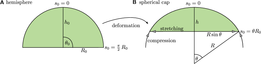
Lenticular liquid shapes have been discussed in literature both at a liquid-liquid interface Princen (1963) and on a solid substrate Widom (1995); Blecua et al. (2006), and analytical solutions for liquid lenses at liquid-liquid interfaces can be obtained analogously. We restrict ourselves here to the symmetric case . The total energy of the system is given by
| (51) |
where is the total area of the liquid lens and the occupied cross-section area within the liquid-liquid interface plane. We use the fact the liquid lens is composed of two spherical caps of equal radius (for the symmetric case) according to the Laplace equation (45), and of equal base radius . Then is the surface of the lens (two spherical caps) and the occupied cross-section area within the liquid-liquid interface plane. Here, denotes the height of the spherical caps, which is related to and via , see also Fig. 10(B) for the involved quantities. In the following, we measure lengths in units of the radius of a spherical droplet of the same volume and thereby introduce reduced quantities , , and . For a fixed volume,
| (52) |
the radius and the height are related by
| (53) |
We can now write the energy (51) as a function of the reduced height , minimize with respect to the reduced height , and find the equilibrium height
| (54) |
as a function of . We obtain the opening angle from the geometric relation
| (55) |
and, finally, the pressure from the Laplace-Young equation
| (56) |
If we use as a function of from eq. (54) in these relations we find and as a function of .
C.2 Elastic lens
For the symmetric case, we can derive an approximative analytical solution for the elastic membrane shape based on a spherical cap approximation. We investigate partially spherical solutions, because, intuitively, the difference between a liquid droplet and a liquid droplet coated with an elastic membrane should be negligible for small interface loads as also suggested by the numerically calculated shapes of elastic lenses. Force balance for an unloaded spherical cap implies a constant tension Landau and Lifschitz (1970) such that, additionally, must hold to fulfill the force balance conditions (28) (i).
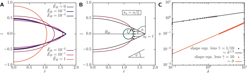
Deforming a hemisphere into a spherical cap by uniform strains leads, however, to anisotropic tensions . The spherical cap has only one free parameter, which is its reduced height , as it already has been introduced above in the context of liquid lenses. From geometrical arguments (see Fig. 10) we can calculate the uniform stretches and for the deformation into a spherical cap,
| (58) |
where is the reduced radius as given by the volume constraint (53) and is the opening angle of the spherical caps according to (55). Obviously because and , i.e., the stretches (13) are anisotropic. Inserting these stretches into the constitutive relations (4) we also obtain anisotropic stresses, . Therefore, assuming constant tensions in a spherical cap formed from a hemispherical rest shape violates the force balance conditions (28). For , i.e., small deviations from the fluid-like behavior deviations from force balance are also small, and we can use spherical caps as an approximation.
Inserting the uniform strains (13) into the constitutive relations (4) gives the stresses and as a function of the reduced spherical cap height . Then we employ the Neumann condition from eq. (49) in the symmetric case, i.e., and , the geometric relation (55) and the volume constraint (53), to obtain
| (59) |
analogously to eq. (57). Solving this equation for gives the height as a function of and . In the fluid regime ( in Figs. 5(A,B)), we have and find for small . In the elastic regime ( in Figs. 5(A,B)), we have , which gives for small . From the Laplace-Young equation (third eq. in (48)), we then find the pressure as a function of ,
| (60) |
and, thus, as a function of and .
C.3 Pogorelov approximation for finite
For the edge of the elastic lens becomes rounded as shown in Fig. 11(A). The curvature at the AB-interface is a characteristic geometric feature of these shapes, which depends on the elastic properties of the capsule and the interface load. In Fig. 5(C), we found a scaling for the curvature from numerical simulations. We can derive this scaling from an adaption of Pogorelov’s theory Pogorelov (1988) as it has been used in Ref. 61; 62. The reader is referred to Fig. 11(B) for the involved geometric quantities. We start from an elastic lens shape for vanishing bending rigidity , which is described by the contour and has a sharp edge at the AB-interface. If the bending rigidity is introduced, the shape becomes rounded at the edge, which is described by an additional displacement field such that
| (61) |
during rounding. Rounding involves two additional energies contributing to the shape: the additional bending energy associated with the bending rigidity and an additional mechanical work performed against that the surface tension because rounding displaces the three phase contact line against the surface tension .
Since the interface load acts in radial direction, it is reasonable to assume that , i.e., only radial shape perturbations occur. This allows us to write the total energy change, induced by bending and pulling against while starting at the elastic lens, as
| (62) | ||||
where describes a small arc length region over which the kink of the shape is rounded and is the radius of the circle in the interface plane, i.e., the radius of the interface cross-section. In eq. (62) we neglect the apparent hoop stretching as well as higher order and constant terms of the bending energy (for a detailed analysis, see Ref. 51). Throughout the following calculations we use approximations for small , which is the turning angle of the shape at the AB-interface and related to the opening angle of the elastic lens via . To find the corresponding characteristic arc length scale on which the shape gets bent at the interface, we non-dimensionalize eq. (62) according to
| (63) | ||||
and recast the energies in (62) as
| (64) | ||||
| (65) |
Minimizing the total energy with respect to we find the scaling relations
| (66) |
The dimensionless integrals in eq. (65) only contribute numerical prefactors; the essential result is the scaling behavior of and . Note that the above scaling relations still depend on . This dependence can be eliminated by employing the symmetric Neumann force balance condition (59), and the geometric relation . In the fluid regime , we have and find . In the elastic regime , we have for small . For small , this leads to
| (67) |
in the two regimes. The above scaling behavior of is verified numerically in Fig. 11(C), where we measured for an elastic lens dependent on for two different values of corresponding to the elastic respectively fluid regime. Inserting these scaling relations into eq. (66) gives
| (68) |
From we finally obtain the scaling laws for the shell’s curvature at the AB-interface
| (69) |
The dependence on the bending modulus, , is universal, i.e., independent of whether we are in the fluid or elastic regime. For comparison, spherical shells which buckle upon deflation have at the spherical rim of the indentation Knoche and Kierfeld (2014b, c).