Direction-Dependent Parity-Time Phase Transition and Non-Reciprocal Directional Amplification with Dynamic Gain-Loss Modulation
Abstract
We show that a dynamic gain-loss modulation in an optical structure can lead to a direction-dependent parity-time () phase transition. The phase transition can be made thresholdless in the forward direction, and yet remains with a non-zero threshold in the backward direction. As a result, non-reciprocal directional amplification can be realized.
There have been significant recent interests in the fundamental quantum physics related to parity-time () symmetry, as well as in the applications of symmetry in both optical and electromagnetic structures Bender and Boettcher (1998); Makris et al. (2008); Guo et al. (2009); Rüter et al. (2010); Lin et al. (2011); Chong et al. (2011); Bittner et al. (2012); Feng et al. (2013); Lumer et al. (2013); Feng et al. (2014); Hodaei et al. (2014); Cerjan et al. (2016). In particular, the connection between symmetry and non-reciprocity has been extensively discussed Huang et al. (2017); Yin and Zhang (2013); Zhou and Chong (2016); Ramezani et al. (2010); Peng et al. (2014); Chang et al. (2014); Nazari et al. (2014); Zhu et al. (2014); Longhi (2009). Optical structures exhibiting symmetry are typically described by scalar, time-independent dielectric functions. These structures cannot exhibit any non-reciprocity in their linear optical properties Jalas et al. (2013); Huang et al. (2017); Yin and Zhang (2013); Fan et al. (2012). In order to achieve non-reciprocal response, most existing works exploit the significant nonlinearity-enhancement provided by the -phase transition Huang et al. (2017); Zhou and Chong (2016); Ramezani et al. (2010); Peng et al. (2014); Chang et al. (2014); Nazari et al. (2014); Zhu et al. (2014). Nevertheless, it has been shown that nonlinear non-reciprocal devices are fundamentally constrained by dynamic reciprocity, which significantly limits the practical functionalities of these devices Shi et al. (2015).
In this paper we propose an alternative route to achieve non-reciprocity in -symmetric structures. We show that non-reciprocal directional amplification can arise in structures under a dynamic material gain-loss modulation. In particular, the gain-loss modulation induces a direction-dependent phase transition that is thresholdless in the forward direction Ge and Stone (2014); Feng et al. (2013); Cerjan et al. (2016), but with a non-zero threshold in the backward direction. Consequently, such a structure enables direction-dependent amplification.
Related to our work, it has been shown that the dynamic modulation of the real part of the dielectric constant can be used to construct optical isolators and circulators Yu and Fan (2009); Wang et al. (2013); Kang et al. (2011); Lira et al. (2012). The underlying dynamics in the systems in Ref. Yu and Fan, 2009; Wang et al., 2013; Kang et al., 2011; Lira et al., 2012 however is Hermitian and is qualitatively different from the non-Hermitian physics that we discuss here, which arise from the modulation of the imaginary part of the dielectric constant. Non-reciprocal directional amplification has been theoretically considered in Ref. Metelmann and Clerk, 2015; Malz et al., 2018; Kamal and Metelmann, 2017; Ruesink et al., 2016; Abdo et al., 2013; Koutserimpas and Fleury, 2018, and experimentally implemented using Josephson junctions or optomechanical interactions Abdo et al. (2013); Fang et al. (2017); Shen et al. (2016); Ruesink et al. (2016). None of these works however made use of -symmetry concepts. Our approach points to a previously unrecognized connection between -symmetry and non-reciprocal physics. From a practical point of view, unlike all existing approach to directional amplification, the proposed scheme here does not rely upon the use of resonators and is inherently broad-band. Furthermore, the gain-loss modulation is more straightforwardly integrable with standard semiconductor laser structures, and can be employed to protect laser sources from back-propagating noises.
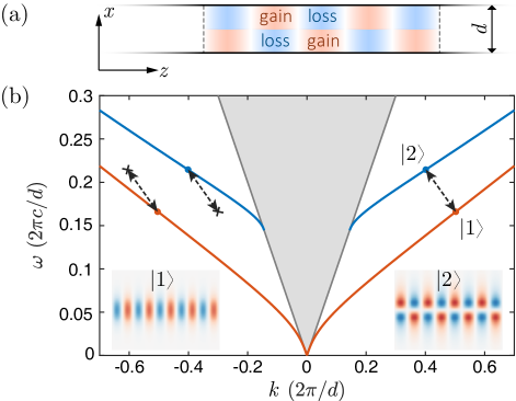
To illustrate the basic concept, we consider the dielectric waveguide structure schematically shown in Fig. 1a. The gain and loss in the waveguide is modulated as a function of space and time. Mathematically, we can represent the modulation in gain and loss by a time varying conductivity as
| (1) |
Here, is the modulation strength. is the modulation profile in the direction. is the wavevector. is the modulation frequency. is the modulation phase. We assume is an odd function of . In an laser waveguide, gain and loss modulations can be achieved by controlling the pumping levels at different positions.
The waveguide without modulation has a photonic band structure as shown in Fig. 1b, which has two bands of modes that are even or odd with respect to the center plane of the waveguide. The field profiles of these modes are shown in the inset of Fig. 1b. Here for simplicity we consider only transverse-electric modes, which have the electric field perpendicular to the -plane. In general, the modulation profile in Eq. 1 can couple modes from the two bands with opposite symmetry, with their frequencies separated by . Considering only two modes involved in the coupling, the electric field in the waveguide can be written as
| (2) |
where is the modal profile in , which are normalized so that are the intensity of the respective modes. and are the wavevector and the frequency of each mode. Defining , the equation of motion in the modulated waveguide can be derived using coupled mode theory Yu and Fan (2009):
| (3) | ||||
where is the wavevector mismatch, and is the coupling strength.
Eq. 3 is in the form of a time-periodic Schrödinger equation with taking the role of time. The Hamiltonian satisfies the symmetry defined as Moiseyev (2011); Luo et al. (2013); Joglekar et al. (2014); Chitsazi et al. (2017)
| (4) |
The definition of stems from the fact that mode is even under parity operation, while mode is odd.
As a result of the symmetry, the Floquet quasi-energies of the system must be either real or complex conjugate pairs 111Please refer to the supplementary for more information.. To obtain the Floquet eigenstates and the quasi-energies, we first solve for the evolution operator defined by :
| (5) |
where . Then, the quasi-energy of the system can be obtained by letting , where is the period of the Hamiltonian along . The obtained quasi-energies are
| (6) |
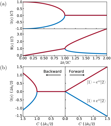
From Eq. 6, we observe that the system has a phase transition controlled by the ratio as shown in Fig. 2a. If the wavevector mismatch dominates over the coupling strength, i.e. , the system is in the exact phase. Both quasi-energies are real, and the Floquet eigenmodes do not experience gain or loss. On the other hand, for small wavevector mismatch, i.e. the system is in the broken phase where the quasi-energies of the system split into complex conjugate pairs. Thus, one of the Floquet modes will be amplified in the system.
We now consider a gain-loss modulation that provides a phase-matched coupling between two modes with different wavefectors in the forward direction as illustrated in Fig. 1b. Such a modulation introduces a direction-dependent phase transition as is shown in Fig. 2b. In the forward direction, . From Eq. 6, the quasi-energies become . Thus the quasi-energies split into complex conjugate pairs as soon as coupling strength increases from , i.e. the system exhibits a thresholdless phase transition Ge and Stone (2014); Feng et al. (2014); Cerjan et al. (2016). For the backward direction however, , and the gain-loss modulation does not provide phase-matched coupling between any pair of modes. Thus, the system exhibits a phase transition with a non-zero threshold in the backward direction.
Such a direction-dependent phase transition gives rise to the effect of non-reciprocal directional amplification in this system. To illustrate this effect, we consider the regime where , and . Under these conditions, the evolution operator can be simplified as
| (7) |
where stand for forward and backward propagations, respectively. In the forward direction, one of the Floquet eigenmode, , is amplified, while the other mode, , is attenuated. Thus, if is the input to the waveguide, then the output becomes , providing amplification to the input mode. In fact, input in the forward direction with any modal profile including , or any of their combination except , will be amplified. In contrast, the system is in the exact phase in the backward direction. The Floquet eigenmodes are and , with both quasi-energies approaching 0. Thus an input mode in the backward direction, with any modal profile, does not experience any gain or loss.
We notice that in general the system described by Eq. 3 is non-Hermitian, and the evolution operator is not unitary. Thus, in general mode propagation in the system does not preserve mode orthogonality or the total energy flux. Instead, for any , the evolution operator in Eq. 5 is sympletic satisfying . Hence, with any input mode profile, the intensity difference between modes and is always conserved. This conservation law is different from that for a system undergoing dynamic modulation in the real part of the dielectric function Yu and Fan (2009), where the sum of the total photon number flux is conserved.
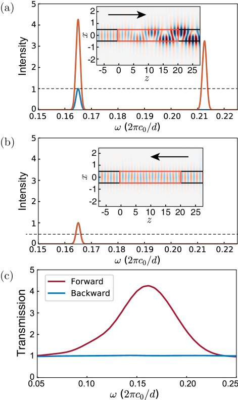
In the following, we numerically demonstrate the non-reciprocal effects predicted above using finite-difference time-domain (FDTD) simulations. We assume a waveguide with a permittivity of , and a width of . We select two modes of the waveguide as shown in Fig. 1b. Mode has a frequency of and a wavevector of , while mode has and . The frequencies and the wavevectors are normalized to and , respectively. All the lengths below are normalized to . A section of the waveguide with a length of is under gain-loss modulation. The modulation has a frequency and a wavevector , chosen to match the two modes in the forward direction. The modulation strength is 1. We input a Gaussian pulse in mode from either left or right with a normalized peak intensity of 1 as shown in Fig. 3a. In the forward direction, the input mode evolves into a linear superposition of and , as is shown in Fig. 3a. The intensity in both modes and exceed unity, indicating the presence of amplification. The intensity difference between the modes and remains unity, in agreement with the conservation law derived analytically above. In the backward direction however, the input mode passes through without amplification or attenuation as is shown in Fig. 3b, again in agreement with the analytical results derived above. The numerical simulation here thus provides a validation of the theory presented above.
The non-reciprocal directional amplification discussed here can operate over a broad bandwidth, provided that modes and are in the parallel region of the even and odd bands in Fig. 1b. Then, if a gain-loss modulation induces a phase-matched coupling between two modes with and , it also induces a phase-matched coupling between modes and Yu and Fan (2009). As a demonstration, in Fig. 3c we show the the mode-to-mode transmission spectrum for the even mode in both directions. In the forward direction, the transmission exceeds unity in a broad frequency range of -, while in the backward direction the transmission is nearly constant at . Thus, significant non-reciprocal directional gain can occur in a broad frequency range with its width comparable to its center frequency. As a result, in practical device applications, the operation bandwidth will only be limited by the gain bandwidth of the materials. The broadband characteristics here is in contrast with existing schemes on directional amplifications, which are all based on resonant interactions and hence are inherently narrow-banded.
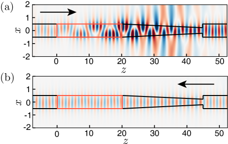
In the structure shown in Fig. 3, the direction-dependent amplification for the even mode is accompanied by the generation of amplitudes in the odd mode. To provide a single mode response with directional amplification, one can use a passive reciprocal structure to filter out the odd mode. An example is shown in Fig. 4, where we have used a tapered waveguide region as a modal filter. The tapered region has the same dielectric constant as the waveguide. It has a length of , and its width linearly changes from to . As is shown in Fig. 4a, in the forward direction, an input mode is amplified by the gain-loss modulation region. Then, since the generated mode is not guided in the narrower part of the tapered region, it leaks out of the waveguide, leaving an amplified mode at the output on the right side. In contrast, in the backward direction, input mode propagates through the tapered region and the modulated region without any amplification, as is shown in Fig. 4b. We note such a filter scheme is based on the modal profile rather than the frequency and hence can preserve the broad-band nature of the device, even in the case where the modulation frequency is small.
With directional gain available, it is straightforward to construct non-reciprocal optical isolation. One can connect the gain-loss modulation region with an absorption region, so that the wave has a net unit-transmission in one direction, while it is attenuated in the other direction. The strength of optical isolation of such a device is tunable. One can tune the contrast ratio, defined by the ratio between the transmission coefficients in the two directions, by adjusting the length of the gain-loss modulated region.
In the above demonstration, we have assumed a modulation frequency of , and a modulation strength of , which corresponds to a modulation strength in the imaginary part of permittivity of . In today’s semiconductor laser technology, the achievable modulation frequency is a few tenth of gigahertz Nakahara et al. (2015), corresponding to a smaller modulation frequency of . The gain coefficient in these lasers typically reaches well over Ma et al. (2013), corresponding to a large gain-loss modulation strength of . Using the coupled mode theory formalism as discussed above, a non-reciprocal directional gain of dB/mm can be achieved in a waveguide similar to what was shown in Fig. 1, assuming a realistic modulation frequency of 50 GHz, and a modulation strength of Note (1). We emphasize here that the method of gain-loss modulation is directly integrable with standard semiconductor laser technology. It can be fabricated as a section of a diode laser waveguide, requiring no additional materials or photonic integration.
In summary, we have shown that dynamic gain-loss modulations in a dielectric waveguide structure can give rise to a direction-dependent phase transition that is thresholdless in the forward direction but with a non-zero threshold in the backward direction. This effect can be used to achieve non-reciprocal directional gain that is broad-band, and the structure is directly integrable with standard semiconductor lasers. Our work points to a previously unexplored connection between symmetry and non-reciprocal physics. Further exploration of this connection may offer new opportunities in studying novel non-Hermitian topological physics in dynamic and non-reciprocal systems Cerjan et al. (2018); Leykam et al. (2017); Zeuner et al. (2015); Malzard et al. (2015); Esaki et al. (2011).
Acknowledgements.
This work is supported by U. S. Air Force Office of Scientific Research (FA9550-16-1-0010, FA9550-17-1-0002).References
- Bender and Boettcher (1998) C. M. Bender and S. Boettcher, Physical Review Letters 80, 5243 (1998).
- Makris et al. (2008) K. G. Makris, R. El-Ganainy, D. N. Christodoulides, and Z. H. Musslimani, Physical Review Letters 100, 103904 (2008).
- Guo et al. (2009) A. Guo, G. J. Salamo, D. Duchesne, R. Morandotti, M. Volatier-Ravat, V. Aimez, G. A. Siviloglou, and D. N. Christodoulides, Physical Review Letters 103, 093902 (2009).
- Rüter et al. (2010) C. E. Rüter, K. G. Makris, R. El-Ganainy, D. N. Christodoulides, M. Segev, and D. Kip, Nature Physics 6, 192 (2010).
- Lin et al. (2011) Z. Lin, H. Ramezani, T. Eichelkraut, T. Kottos, H. Cao, and D. N. Christodoulides, Physical Review Letters 106, 213901 (2011).
- Chong et al. (2011) Y. D. Chong, L. Ge, and A. D. Stone, Physical Review Letters 106, 093902 (2011).
- Bittner et al. (2012) S. Bittner, B. Dietz, U. Günther, H. L. Harney, M. Miski-Oglu, A. Richter, and F. Schäfer, Physical Review Letters 108, 024101 (2012).
- Feng et al. (2013) L. Feng, Y.-L. Xu, W. S. Fegadolli, M.-H. Lu, J. E. B. Oliveira, V. R. Almeida, Y.-F. Chen, and A. Scherer, Nature Materials 12, 108 (2013).
- Lumer et al. (2013) Y. Lumer, Y. Plotnik, M. C. Rechtsman, and M. Segev, Physical Review Letters 111, 263901 (2013).
- Feng et al. (2014) L. Feng, Z. J. Wong, R.-M. Ma, Y. Wang, and X. Zhang, Science 346, 972 (2014).
- Hodaei et al. (2014) H. Hodaei, M.-A. Miri, M. Heinrich, D. N. Christodoulides, and M. Khajavikhan, Science 346, 975 (2014).
- Cerjan et al. (2016) A. Cerjan, A. Raman, and S. Fan, Physical Review Letters 116, 203902 (2016).
- Huang et al. (2017) Y. Huang, Y. Shen, C. Min, S. Fan, and G. Veronis, Nanophotonics 6, 977 (2017).
- Yin and Zhang (2013) X. Yin and X. Zhang, Nature Materials 12, 175 (2013).
- Zhou and Chong (2016) X. Zhou and Y. D. Chong, Optics Express 24, 6916 (2016).
- Ramezani et al. (2010) H. Ramezani, T. Kottos, R. El-Ganainy, and D. N. Christodoulides, Physical Review A 82, 043803 (2010).
- Peng et al. (2014) B. Peng, S. K. Özdemir, F. Lei, F. Monifi, M. Gianfreda, G. L. Long, S. Fan, F. Nori, C. M. Bender, and L. Yang, Nature Physics 10, 394 (2014).
- Chang et al. (2014) L. Chang, X. Jiang, S. Hua, C. Yang, J. Wen, L. Jiang, G. Li, G. Wang, and M. Xiao, Nature Photonics 8, 524 (2014).
- Nazari et al. (2014) F. Nazari, N. Bender, H. Ramezani, M. Moravvej-Farshi, D. N. Christodoulides, and T. Kottos, Optics Express 22, 9574 (2014).
- Zhu et al. (2014) X. Zhu, H. Ramezani, C. Shi, J. Zhu, and X. Zhang, Physical Review X 4, 031042 (2014).
- Longhi (2009) S. Longhi, Physical Review Letters 103, 123601 (2009).
- Jalas et al. (2013) D. Jalas, A. Petrov, M. Eich, W. Freude, S. Fan, Z. Yu, R. Baets, M. Popović, A. Melloni, J. D. Joannopoulos, M. Vanwolleghem, C. R. Doerr, and H. Renner, Nature Photonics 7, 579 (2013).
- Fan et al. (2012) S. Fan, R. Baets, A. Petrov, Z. Yu, J. D. Joannopoulos, W. Freude, A. Melloni, M. Popovic, M. Vanwolleghem, D. Jalas, M. Eich, M. Krause, H. Renner, E. Brinkmeyer, and C. R. Doerr, Science 335, 38 (2012).
- Shi et al. (2015) Y. Shi, Z. Yu, and S. Fan, Nature Photonics 9, 388 (2015).
- Ge and Stone (2014) L. Ge and A. D. Stone, Physical Review X 4, 031011 (2014).
- Yu and Fan (2009) Z. Yu and S. Fan, Nature Photonics 3, 91 (2009).
- Wang et al. (2013) D.-W. Wang, H.-T. Zhou, M.-J. Guo, J.-X. Zhang, J. Evers, and S.-Y. Zhu, Physical Review Letters 110, 093901 (2013).
- Kang et al. (2011) M. S. Kang, A. Butsch, and P. S. J. Russell, Nature Photonics 5, 549 (2011).
- Lira et al. (2012) H. Lira, Z. Yu, S. Fan, and M. Lipson, Physical Review Letters 109, 033901 (2012).
- Metelmann and Clerk (2015) A. Metelmann and A. A. Clerk, Physical Review X 5, 021025 (2015).
- Malz et al. (2018) D. Malz, L. D. Tóth, N. R. Bernier, A. K. Feofanov, T. J. Kippenberg, and A. Nunnenkamp, Physical Review Letters 120, 023601 (2018).
- Kamal and Metelmann (2017) A. Kamal and A. Metelmann, Physical Review Applied 7, 034031 (2017).
- Ruesink et al. (2016) F. Ruesink, M.-A. Miri, A. Alù, and E. Verhagen, Nature Communications 7, 13662 (2016).
- Abdo et al. (2013) B. Abdo, K. Sliwa, L. Frunzio, and M. Devoret, Physical Review X 3, 031001 (2013).
- Koutserimpas and Fleury (2018) T. T. Koutserimpas and R. Fleury, Physical Review Letters 120, 087401 (2018).
- Fang et al. (2017) K. Fang, J. Luo, A. Metelmann, M. H. Matheny, F. Marquardt, A. A. Clerk, and O. Painter, Nature Physics 13, 465 (2017).
- Shen et al. (2016) Z. Shen, Y. L. Zhang, Y. Chen, C. L. Zou, Y. F. Xiao, X. B. Zou, F. W. Sun, G. C. Guo, and C. H. Dong, Nature Photonics 10, 657 (2016).
- Moiseyev (2011) N. Moiseyev, Physical Review A 83, 052125 (2011).
- Luo et al. (2013) X. Luo, J. Huang, H. Zhong, X. Qin, Q. Xie, Y. S. Kivshar, and C. Lee, Physical Review Letters 110, 243902 (2013).
- Joglekar et al. (2014) Y. N. Joglekar, R. Marathe, P. Durganandini, and R. K. Pathak, Physical Review A 90, 040101 (2014).
- Chitsazi et al. (2017) M. Chitsazi, H. Li, F. M. Ellis, and T. Kottos, Physical Review Letters 119, 093901 (2017).
- Note (1) Please refer to the supplementary for more information.
- Nakahara et al. (2015) K. Nakahara, Y. Wakayama, T. Kitatani, T. Taniguchi, T. Fukamachi, Y. Sakuma, and S. Tanaka, IEEE Photonics Technology Letters 27, 534 (2015).
- Ma et al. (2013) M.-l. Ma, J. Wu, Y.-q. Ning, F. Zhou, M. Yang, X. Zhang, J. Zhang, and G.-y. Shang, Optics Express 21, 10335 (2013).
- Cerjan et al. (2018) A. Cerjan, M. Xiao, L. Yuan, and S. Fan, Physical Review B 97, 075128 (2018).
- Leykam et al. (2017) D. Leykam, K. Y. Bliokh, C. Huang, Y. D. Chong, and F. Nori, Physical Review Letters 118, 040401 (2017).
- Zeuner et al. (2015) J. M. Zeuner, M. C. Rechtsman, Y. Plotnik, Y. Lumer, S. Nolte, M. S. Rudner, M. Segev, and A. Szameit, Physical Review Letters 115, 040402 (2015).
- Malzard et al. (2015) S. Malzard, C. Poli, and H. Schomerus, Physical Review Letters 115, 200402 (2015).
- Esaki et al. (2011) K. Esaki, M. Sato, K. Hasebe, and M. Kohmoto, Physical Review B 84, 205128 (2011).