Effect of -site substitution and the pressure on stability of Fe12: A first-principles study
Abstract
We theoretically study the structural stability of Fe12 with the ThMn12 structure (: rare-earth element, La, Pr, Nd, Sm, Gd, Dy, Ho, Er, Tm, Lu, Y, or Sc, or group-IV element, Zr or Hf) based on density functional theory. The formation energy has a strong correlation with the atomic radius of . The formation energy relative to simple substances decreases as the atomic radius decreases, except for Sc and Hf, while that relative to Fe17 and bcc Fe has a minimum for Dy. The present results are consistent with recent experimental reports in which the partial substitution of Zr at sites stabilizes Fe12-type compounds with Nd or Sm. Our results also suggest that the partial substitution of Y, Dy, Ho, Er, or Tm for Nd or Sm is a possible way to enhance the stability of the ThMn12 structure. Under hydrostatic pressure, the formation enthalpy decreases up to 6 GPa and then starts to increase at higher pressures.
I Introduction
The saturation magnetization and magnetocrystalline anisotropy are key quantities that define the performance of a magnet compound. A high content of iron is considered preferable for the former, while rare-earth elements are used as a source of the latter in many cases. From this viewpoint, Fe12-type compounds (: a rare-earth element) with the ThMn12 structure have been studied as promising magnet compounds for a long time. Buschow (1991); Hirayama et al. (2015a); Miyake and Akai (2018) Fe12 contains a higher atomic percentage of Fe (92 at%) than other magnet compounds, e.g., Nd2Fe14B (82 at%) and Fe17 (89 at%). A quantitative prediction was presented by theoretical work on NdFe12N Miyake et al. (2014) and then confirmed by the experimental realization of NdFe12N by epitaxial growth. Hirayama et al. (2015b) Here, N is introduced to enhance the magnetic properties, Yang et al. (1991a, b) and the effects of other typical elements have also been theoretically studied to improve the magnetic properties. Harashima et al. (2015); Fukazawa et al. (2017)
One issue is that Fe12 is considered to be thermodynamically unstable, Coehoorn (1990) and partial substitution for Fe atoms is essential for the stabilization of a bulk system with the ThMn12 structure. In the absence of stabilizing elements, Fe17 phases are typically generated instead of Fe12. Margarian et al. (1994); Suzuki (2017) Ti is a typical stabilizing element. SmFe11Ti Ohashi et al. (1988a, b) and NdFe11TiN Yang et al. (1991a, b) were synthesized around 1990. A disadvantage of the introduction of stabilizing elements is the significant reduction in the saturation magnetization. As a matter of fact, both SmFe11Ti and NdFe11TiN have an inferior magnetization compared to that of Nd2Fe14B (e.g., summarized in Table 1 of Ref. Hirosawa et al., 2017).
In order to overcome the reduction in the magnetization, a search for another stabilizing element has been conducted. Stabilization by substituting Fe with several elements (V, Cr, Mn, Mo, W, Al, and Si) have been reported so far, Felner (1980); Yang et al. (1981); Mooij and Buschow (1988); Ohashi et al. (1988a); Müller (1988); Wang et al. (1988) but the reduction in the magnetization is still large. It is theoretically suggested that Co can stabilize the ThMn12 structure and retain a large magnetic moment. Harashima et al. (2016) Though a high magnetization in Sm(Fe,Co)12 films has been experimentally reported recently, Hirayama et al. (2017) thermodynamic stabilization by doping with Co has yet to be confirmed.
Recently, (Nd,Zr)(Fe,Co)11.5Ti0.5Nα and (Sm,Zr)(Fe,Co)11.5Ti0.5 were synthesized by the strip casting method, Suzuki et al. (2014); Sakuma et al. (2016); Kuno et al. (2016); Suzuki et al. (2016) which is more practical in industrial applications than the epitaxial growth. Although these compounds contain a smaller amount of Ti than previously synthesized Fe12-type compounds without Zr, the ThMn12 structure is realized. This suggests that the partial occupation of Zr at the sites contributes to the stabilization of the ThMn12 structure. Therefore, the substitution of (not Fe sites) is another possible route for stabilizing Fe12-type compounds.
In the present work, we theoretically examine a series of elements— La, Pr, Sm, Gd, Dy, Ho, Er, Tm, Lu, Y, Sc, Zr, and Hf—as possible stabilizing elements that occupy the rare-earth sites in Fe12. We calculate the formation energy of Fe12 relative to (i) simple substances and (ii) Fe17 and bcc Fe based on density functional theory and analyze the dependence. The obtained results are discussed in connection with experiments on the partial substitution of Zr for Nd or Sm. We then study the effect of the hydrostatic pressure in terms of the stability of Fe12. This paper is organized as follows. The computational methods are described in Sec. II. The calculated formation energy of Fe12 and the effect of the hydrostatic pressure are presented in Sec. III. The paper is concluded in Sec. IV.
II Calculation methods
We perform first-principles calculations by using QMAS (the Quantum MAterials Simulator), Qm (2) which is based on density functional theory Hohenberg and Kohn (1964); Kohn and Sham (1965) and the projector augmented-wave method. Blöchl (1994); Kresse and Joubert (1999) We use the Perdew–Burke–Ernzerhof (PBE) formula Perdew et al. (1996) in the generalized gradient approximation (GGA) for the exchange-correlation energy functional. We sample 8 8 8 points, and the cutoff energy for the plane wave basis is set to 40.0 Ry. The 4 electrons of Pr, Nd, Sm, Gd, Dy, Ho, Er, and Tm atoms are treated as spin-polarized open-core states, and those of the Lu atom are treated as core states. The number of occupied 4 states is fixed to 2 (Pr), 3 (Nd), 5 (Sm), 7 (Gd), 9 (Dy), 10 (Ho), 11 (Er), 12 (Tm), and 14 (Lu). The electron configuration is determined by Hund’s first rule. For light rare-earth elements (from Pr to Gd), all 4 electrons are assumed to be in minority spin states. For heavy rare-earth elements (from Dy to Tm), the minority spin states of the 4 orbitals are fully occupied by seven electrons, and the other electrons are in majority spin states. Note that the local spin moment at is antiparallel to the total spin moment. Spin-orbit coupling is not included in the self-consistent calculation. The reliability of the open-core treatment has been discussed, e.g., in Ref. Tatetsu et al., 2018, and we also check the reliability by calculating the formation energy with GGA , as shown in Appendix A.
We study Fe12 with the ThMn12 structure for La, Pr, Nd, Sm, Gd, Dy, Ho, Er, Tm, Lu, Y, and Sc—rare-earth elements—and Zr and Hf—group-IV elements. The preferential sites for the group-IV elements are discussed in Appendix B. As reference systems, Fe17 with the Th2Zn17 structure, Fe17 with the Th2Ni17 structure, and the simple substances of and Fe are studied. For Fe, the bcc structure is assumed; for La, Pr, Nd, and Sm, the dhcp structure is assumed; and for Gd, Dy, Ho, Er, Tm, Lu, Y, Sc, Zr, and Hf, the hcp structure is assumed. The structures of Fe12, Fe17, and the simple substances are computationally optimized. The calculation well-reproduces the experimental lattice constants for existing crystals, e.g., Sm2Fe17. Coey and Sun (1990); Koyama and Fujii (2000); Hirayama et al. (2016) The calculated lattice constants and the inner coordinates of Fe12 and Fe17 are shown in Sec. SA of the Supplemental Material. sup From the obtained structures of the simple substances, we deduce the atomic radii ( and ) of the elements: half of the shortest bond lengths is used as the atomic radii. These values are tabulated in Sec. SB of the Supplemental Material. sup
III Results and Discussion
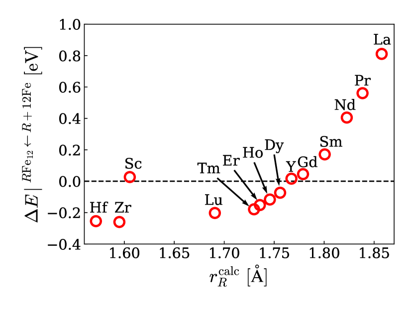
We first discuss the values of the energy for forming Fe12 from the simple substances and Fe. Let us denote the formation energy of a substance via the chemical reaction by . Figure 1 shows the values of as a function of . This energy is calculated by
| (1) |
where denotes the total energy of the system in brackets per formula unit. There is a trend toward a decrease in the formation energy as the calculated atomic radii () decreases. When is small, however, this trend does not hold. The value for Sc is exceptionally high. The value for Hf is slightly higher than that for Zr, although Hf has a smaller than Zr. Although we do not explicitly show other factors, e.g., the valency, than the atomic size, they may affect the results.
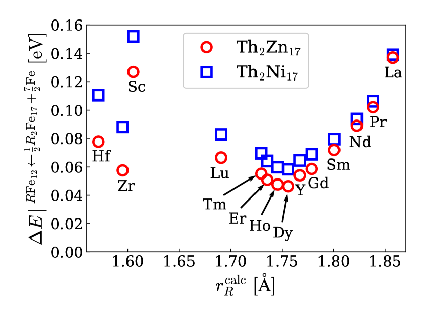
Considering the experimental indication that the Fe17 phase is a competing phase, we also calculate the formation energy of Fe12 relative to and bcc Fe, defined by
| (2) |
We consider two cases for Fe17: one with the (rhombohedral) Th2Zn17 structure and the other with the (hexagonal) Th2Ni17 structure. The energy difference between the two structures is discussed in Sec. SC of the Supplemental Material. sup Figure 2 shows the values of for the two cases. The qualitative behavior is insensitive to the choice of structures. As decreases to 1.75 Å, decreases. It has a minimum for Dy and increases as decreases further, which is in sharp contrast with the behavior of . The formation energy is positive even for Dy. This indicates that one cannot make the Fe12 phase more stable than Fe17, and partial substitution for Fe is necessary for stabilizing the ThMn12 structure. However, an appropriate choice of possibly reduces the necessary amount of stabilizing elements that partially substitute for Fe in synthesizing a material with the ThMn12 structure.
As mentioned in Sec. I, (Nd,Zr)(Fe,Co)11.5Ti0.5Nα and (Sm,Zr)(Fe,Co)11.5Ti0.5 have been synthesized. Suzuki et al. (2014); Sakuma et al. (2016); Kuno et al. (2016); Suzuki et al. (2016) These experiments suggest that the partial substitution of Zr for Nd and Sm enhances the stability of Nd(Fe,Co,Ti)12N and Sm(Fe,Co,Ti)12, respectively. The question is if there is a better element than Zr that contributes to the stabilization of the ThMn12 structure. Figure 2 shows that the formation energy (Eq. (2)) is lower for Y, Dy, Ho, Er, and Tm than for Zr. We can expect that the partial substitution of these elements for Nd or Sm enhances the stability of the ThMn12 structure more than Zr.
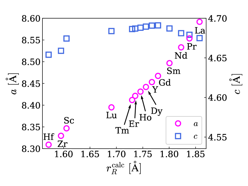
The above results imply that the size of is essential in the stability of Fe12. Figure 3 shows the lattice constants and . The axis shortens as decreases, while the axis is insensitive to . This trend is consistent with the experimental observation that in (Nd,Zr)(Fe,Co)11.5Ti0.5Nα decreases with increasing Zr concentration, whereas is insensitive to the Zr concentration. Sakuma et al. (2016); Suzuki et al. (2016)
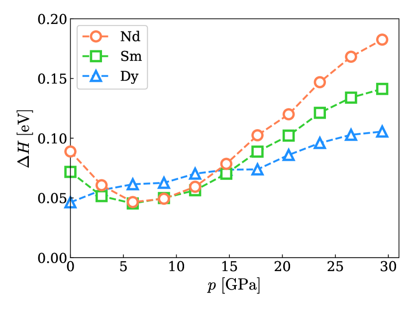
These results motivate us to consider a possibility that applied pressure stabilizes Fe12. To discuss the stability under hydrostatic pressure, we estimate the formation enthalpy defined as follows:
| (3) |
where denotes the enthalpy of the system in brackets under pressure . At 0, is equivalent to . We perform computational optimization of the structure of Fe12, Fe17 with the rhombohedral Th2Zn17 structure, and bcc Fe under hydrostatic pressure. The applied pressure shrinks NdFe12 anisotropically (see Sec. SE of the Supplemental Material sup ). Its axis is shortened more than the axis. The tendency of to be more susceptible than was seen also in their dependence on the atomic radius of , as seen in Fig. 3. The axis becomes similar to that of DyFe12 at 4 GPa, and it becomes similar to that of ZrFe12 at 10 GPa. The formation enthalpy as a function of the pressure for Nd and Sm is shown in Fig. 4. As the pressure increases, the values of decrease up to 6 GPa and then start to increase when the pressure increases further. Although applying a pressure cannot lead to a negative enthalpy, it is expected that amount of stabilizing elements for Fe, such as Ti, can be reduced by synthesis under a hydrostatic pressure of 6 GPa. Admittedly, the pressure is too high to be applied in an industrial production process, the pressure is experimentally applicable and it may offer useful information in a viewpoint of stabilization by controlling the lattice. We confirmed that further reduction cannot be obtained in the case of Dy as shown in Fig. 4.
The qualitative difference in the pressure dependencies shown in Fig. 4 can be explained as follows. Because we are considering a temperature of zero, the enthalpy under a finite pressure is written as
| (4) | ||||
| (5) |
where is the volume of the system under the pressure and is a coefficient that is related to the bulk modulus, , by . In the first order of , the increase in the enthalpy is proportional to the volume at zero pressure. It follows from the second-order term of that a phase is more easily stabilized by pressure when it is softer. This can be expressed in a more general form by noting that the higher-order terms are written as . This is a general expression of “softness” because it refers to the volume change under a given pressure .
At a pressure of zero, the gradient of in Eq. (3) is determined by a difference in the volume at a pressure of zero, .
| (6) |
denotes the volume of the system in brackets per formula unit at 0. The values of are Å3 for Nd, Å3 for Sm, and Å3 for Dy, respectively. This is consistent with the behavior of at a low pressure shown in Fig. 4.
In the second-order approximation, in Eq. (3) can be written as
| (7) | ||||
| (8) |
where
| (9) | ||||
| (10) |
denotes the coefficient of the system.
Within the second-order approximation, the minimum of always exists at when and hold, or more intuitively, when Fe12 is smaller and harder than Fe17 at a temperature of zero. The values estimated from our first-principles calculations are Å3/GPa and Å3 for Nd. These values enable us to predict the existence of the dip from the information at a pressure of zero. Note that, however, Eq. (8) well-describes the behavior of the curves in Fig. 4 only for small pressures. The valid range does not cover the argument of the minimum , . The higher-order terms omitted in Eq. (7) take effect under high pressure and change the minimum of from 24 GPa to 6 GPa.
IV Conclusion
We have performed first-principles calculations of Fe12, where La, Pr, Nd, Sm, Gd, Dy, Ho, Er, Tm, Lu, Y, Sc, Zr, and Hf are considered. The formation energy relative to simple substances becomes lower as the atomic radius of becomes smaller, except for Sc and Hf. The stability of Fe12 relative to the Fe17 phase was also discussed. We found that ZrFe12 has a lower formation energy than NdFe12 and SmFe12. This is consistent with the experimental results for the synthesis of (Nd,Zr)(Fe,Co)11.5Ti0.5Nα and (Sm,Zr)(Fe,Co)11.5Ti0.5. We also found that Y, Dy, Ho, Er, and Tm are possible candidates for enhancing the stability of Nd- or Sm- based Fe12-type compounds. The effect of hydrostatic pressure was also discussed in terms of the stability of the NdFe12, SmFe12, and DyFe12 phases. In the cases for NdFe12 and SmFe12, a hydrostatic pressure of 6 GPa was found to contribute to the stability of the phases, although the formation enthalpy is still positive.
Acknowledgements.
The authors would like to thank Kiyoyuki Terakura, Shoji Ishibashi, Satoshi Hirosawa and Hisazumi Akai for fruitful discussions. This work was supported by the Elements Strategy Initiative Project under the auspices of MEXT, by the “Materials research by Information Integration” Initiative (MI2I) project of the Support Program for Starting Up Innovation Hub from the Japan Science and Technology Agency (JST), and also by MEXT as a social and scientific priority issue (Creation of new functional Devices and high-performance Materials to Support next-generation Industries; CDMSI) to be tackled by using a post-K computer. Computations were partly carried out using the facilities of the Supercomputer Center, the Institute for Solid State Physics, the University of Tokyo, and the supercomputer of ACCMS, Kyoto University and the K computer provided by the RIKEN Advanced Institute for Computational Science (Project IDs:hp150014, hp160227, hp170100, and hp170269).Appendix A Comparison between GGA open-core and GGA
| Eq. (1) | Eq. (2) | |
|---|---|---|
| GGA open-core | 0.405 | 0.084 |
| GGA | 0.395 | 0.105 |
In this appendix, we discuss the reliability of the open-core treatment for 4 electrons by comparison with the calculation with the GGA method. We calculate the total energy of NdFe12 and rhombohedral Nd2Fe17 with the GGA method. The crystal structures are optimized within the scheme. We use 5 eV as a value of for the Nd 4 orbitals. Table 1 presents the formation energies calculated with Eqs. (1) and (2). The formation energy calculated with the GGA open-core treatment agrees with the value calculated with the GGA .
Appendix B Substitution of group-IV elements (Zr, Ti, and Hf)
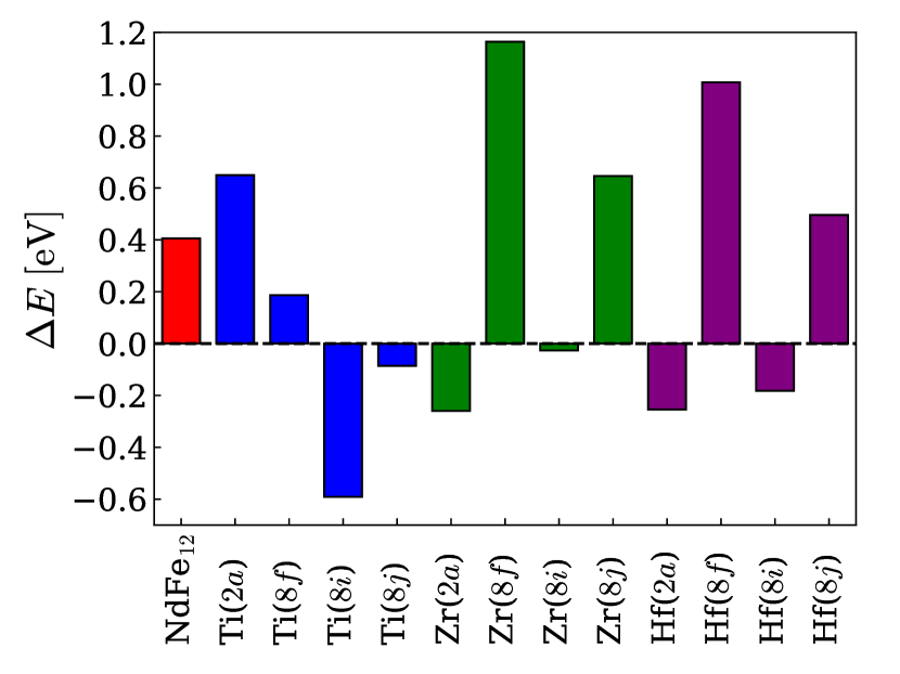
In order to investigate the site preference of group-IV elements Ti, Zr, and Hf for the substitution in NdFe12, we calculate Fe12 ( substitution) and NdFe (8, 8, and 8 substitution) with structure optimization. Then, we calculate their formation energies from the simple Fe, Nd, and phases. In the case of substitution, we consider the formation energy of Fe12 plus the simple Nd phase from the simple Fe, Nd, and phases:
| (11) |
In the other cases, we consider the formation energy of NdFe plus the simple Fe phase from the simple Fe, Nd, and phases:
| (12) |
Therefore, we nominally use the common reference system (Nd++12Fe) to the cases.
The results are shown in Fig. 5. Ti(8), Zr(2), and Hf(2) are the preferential sites for substitution. As for Hf, the 8 site is as stable as the 2 site. The values of for the substituted systems are much smaller than that for NdFe12. Therefore, those elements can work positively for the stabilization of the ThMn12 phase.
We also evaluate the magnetic moments and magnetizations of the systems considered. Figure 6 shows the magnetic moment [/f.u.] and magnetization [T], where is the vacuum permeability. The magnetization is estimated from the calculated magnetic moment , volume , and Bohr magneton by . The values denoted by the open symbols include the value of 3.273 as the contribution from the Nd 4 electrons [: Lande g-factor; : total angular momentum of the Nd 4 electrons]. The values denoted by the filled symbols do not include this contribution.
The magnetic moment (circle) for Fe12 [denoted by ] in the figure is much less than that for NdFe12. Though it mainly originates from the lack of a Nd 4 moment, the differences are larger than of Nd, which can be seen from the difference between the red open circle and the red filled circle. The magnetizations are also reduced by substitution, as seen from the magnetic moment, but the amounts of reduction in the magnetizations are close to the contribution from the Nd 4 moment. This is because substitution shrinks the volume, and this shrinkage cancels some of the reduction. Eventually, the reduction in the magnetization falls close to the Nd 4 moment.
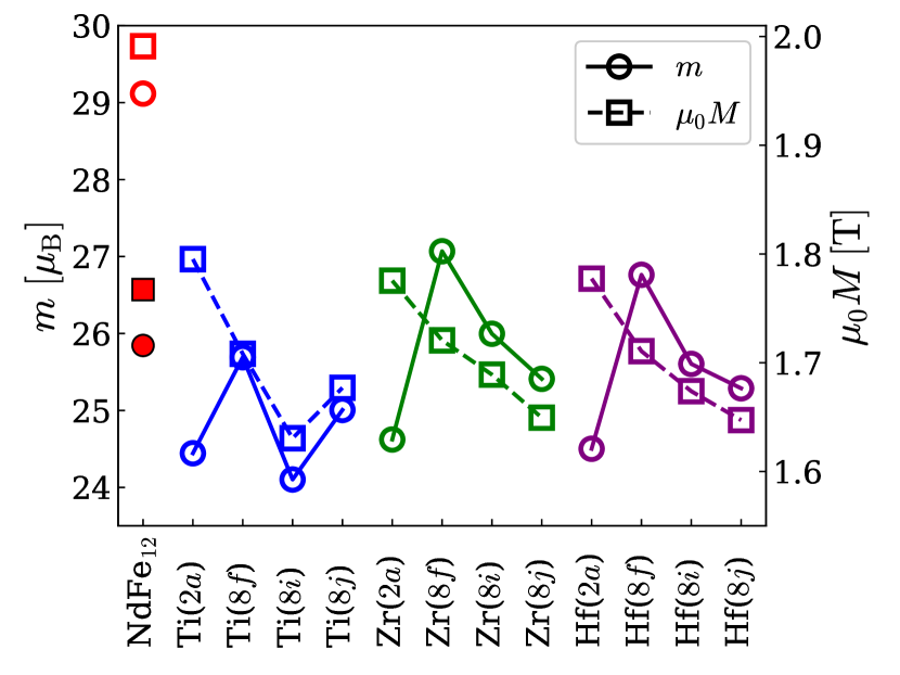
For the substitution of Ti for the Fe sites (8, 8, and 8), the magnetic moment is drastically reduced, which can be explained by Friedel’s concept of a virtual bound state. Friedel (1958); Verhoef et al. (1988); Miyake et al. (2014) As for NdFe11Zr and NdFe11Hf, the reduction in is moderate. However, the reduction in terms of the magnetization, , is significantly large owing to the volume expansion caused by the introduction of Zr and Hf.
References
- Buschow (1991) K. H. J. Buschow, J. Magn. Magn. Mater. 100, 79 (1991).
- Hirayama et al. (2015a) Y. Hirayama, T. Miyake, and K. Hono, JOM 67, 1344 (2015a).
- Miyake and Akai (2018) T. Miyake and H. Akai, J. Phys. Soc. Jpn. 87, 041009 (2018).
- Miyake et al. (2014) T. Miyake, K. Terakura, Y. Harashima, H. Kino, and S. Ishibashi, J. Phys. Soc. Jpn. 83, 043702 (2014).
- Hirayama et al. (2015b) Y. Hirayama, Y. K. Takahashi, S. Hirosawa, and K. Hono, Scr. Mater. 95, 70 (2015b).
- Yang et al. (1991a) Y. C. Yang, X. D. Zhang, L. S. Kong, Q. Pan, and S. L. Ge, Solid State Commun. 78, 317 (1991a).
- Yang et al. (1991b) Y. C. Yang, X. D. Zhang, S. L. Ge, Q. Pan, L. S. Kong, H. Li, J. L. Yang, B. S. Zhang, Y. F. Ding, and C. T. Ye, J. Appl. Phys. 70, 6001 (1991b).
- Harashima et al. (2015) Y. Harashima, K. Terakura, H. Kino, S. Ishibashi, and T. Miyake, Phys. Rev. B 92, 184426 (2015).
- Fukazawa et al. (2017) T. Fukazawa, H. Akai, Y. Harashima, and T. Miyake, J. Appl. Phys. 122, 053901 (2017).
- Coehoorn (1990) R. Coehoorn, Phys. Rev. B 41, 11790 (1990).
- Margarian et al. (1994) A. Margarian, J. B. Dunlop, R. K. Day, and W. Kalceff, J. Appl. Phys. 76, 6153 (1994).
- Suzuki (2017) H. Suzuki, AIP Adv. 7, 056208 (2017).
- Ohashi et al. (1988a) K. Ohashi, Y. Tawara, R. Osugi, J. Sakurai, and Y. Komura, J. Less-Common Met. 139, L1 (1988a).
- Ohashi et al. (1988b) K. Ohashi, Y. Tawara, R. Osugi, and M. Shimao, J. Appl. Phys. 64, 5714 (1988b).
- Hirosawa et al. (2017) S. Hirosawa, M. Nishino, and S. Miyashita, Adv. Nat. Sci.: Nanosci. Nanotechnol. 8, 013002 (2017).
- Felner (1980) I. Felner, J. Less-Common Met. 72, 241 (1980).
- Yang et al. (1981) Y. C. Yang, B. Kebe, W. J. James, J. Deportes, and W. Yelon, J. Appl. Phys. 52, 2077 (1981).
- Mooij and Buschow (1988) D. B. D. Mooij and K. H. J. Buschow, J. Less-Common Met. 136, 207 (1988).
- Müller (1988) A. Müller, J. Appl. Phys. 64, 249 (1988).
- Wang et al. (1988) X. Z. Wang, B. Chevalier, T. Berlureau, J. Etourneau, J. M. D. Coey, and J. M. Cadogan, J. Less-Common Met. 138, 235 (1988).
- Harashima et al. (2016) Y. Harashima, K. Terakura, H. Kino, S. Ishibashi, and T. Miyake, J. Appl. Phys. 120, 203904 (2016).
- Hirayama et al. (2017) Y. Hirayama, Y. K. Takahashi, S. Hirosawa, and K. Hono, Scr. Mater. 138, 62 (2017).
- Suzuki et al. (2014) S. Suzuki, T. Kuno, K. Urushibata, K. Kobayashi, N. Sakuma, K. Washio, H. Kishimoto, A. Kato, and A. Manabe, AIP Adv. 4, 117131 (2014).
- Sakuma et al. (2016) N. Sakuma, S. Suzuki, T. Kuno, K. Urushibata, K. Kobayashi, M. Yano, A. Kato, and A. Manabe, AIP Adv. 6, 056023 (2016).
- Kuno et al. (2016) T. Kuno, S. Suzuki, K. Urushibata, K. Kobayashi, N. Sakuma, M. Yano, A. Kato, and A. Manabe, AIP Adv. 6, 025221 (2016).
- Suzuki et al. (2016) S. Suzuki, T. Kuno, K. Urushibata, K. Kobayashi, N. Sakuma, K. Washio, M. Yano, A. Kato, and A. Manabe, J. Magn. Magn. Mater. 401, 259 (2016).
- Qm (2) http://qmas.jp/.
- Hohenberg and Kohn (1964) P. Hohenberg and W. Kohn, Phys. Rev. 136, B864 (1964).
- Kohn and Sham (1965) W. Kohn and L. J. Sham, Phys. Rev. 140, A1133 (1965).
- Blöchl (1994) P. E. Blöchl, Phys. Rev. B 50, 17953 (1994).
- Kresse and Joubert (1999) G. Kresse and D. Joubert, Phys. Rev. B 59, 1758 (1999).
- Perdew et al. (1996) J. P. Perdew, K. Burke, and M. Ernzerhof, Phys. Rev. Lett. 77, 3865 (1996).
- Tatetsu et al. (2018) Y. Tatetsu, Y. Harashima, T. Miyake, and Y. Gohda, Phys. Rev. Materials 2, 074410 (2018).
- Coey and Sun (1990) J. M. D. Coey and H. Sun, J. Magn. Magn. Mater. 87, L251 (1990).
- Koyama and Fujii (2000) K. Koyama and H. Fujii, Phys. Rev. B 61, 9475 (2000).
- Hirayama et al. (2016) Y. Hirayama, A. K. Panda, T. Ohkubo, and K. Hono, Scr. Mater. 120, 27 (2016).
- (37) See Supplemental Material for (SA) the lattice constants of Fe12 and Fe17, (SB) the calculated atomic radii of and Fe, (SC) the difference in the total energies of rhombohedral and hexagonal Fe17, (SD) the bond lengths in Fe12, and (SE) the lattice distortion in NdFe12 and Nd2Fe17 induced by hydrostatic pressure.
- Friedel (1958) J. Friedel, Il Nuovo Cimento (1955-1965) 7, 287 (1958).
- Verhoef et al. (1988) R. Verhoef, F. R. de Boer, Z. Zhi-dong, and K. H. J. Buschow, J. Magn. Magn. Mater. 75, 319 (1988).