Triple line destabilization – Tuning film thickness through meniscus curvature
Abstract
For partially wetting fluids, previous results suggest that the thickness and the dewetting velocity of gravity driven films are uniquely determined by the triple line dynamics. In contrast, when flushing aqueous liquids through polymer tubes, our measurements show that the dewetting velocity and thickness can be selected. The control parameter is pressure, i.e. the macroscopic curvature of the meniscus. Our results demonstrate directly the major role played by the macroscopic geometry in the stability of a dynamic meniscus as predicted by Eggers (Phys. Rev. Lett. 93, 094502 (2004)).
pacs:
I Introduction
When a solid substrate is immersed in a liquid bath, capillary forces distort the liquid/air interface close to the solid and a static meniscus is established. The characteristic length which emerges from the competition between capillary and hydrostatic pressures is the capillary length where is liquid surface tension, the density and the acceleration of gravity. For a wetting liquid, pulling the substrate out of the bath entrains a film. As a result of the competition between capillary forces and viscous dissipation, film thickness varies as as predicted by Landau, Levich and Derjaguin (LLD) [1, 2]. The control parameter is the capillary number which compares viscous dissipation to capillary pressure gradients, where is the liquid viscosity and the pull-out velocity. This law has been verified experimentally for capillary numbers [3].
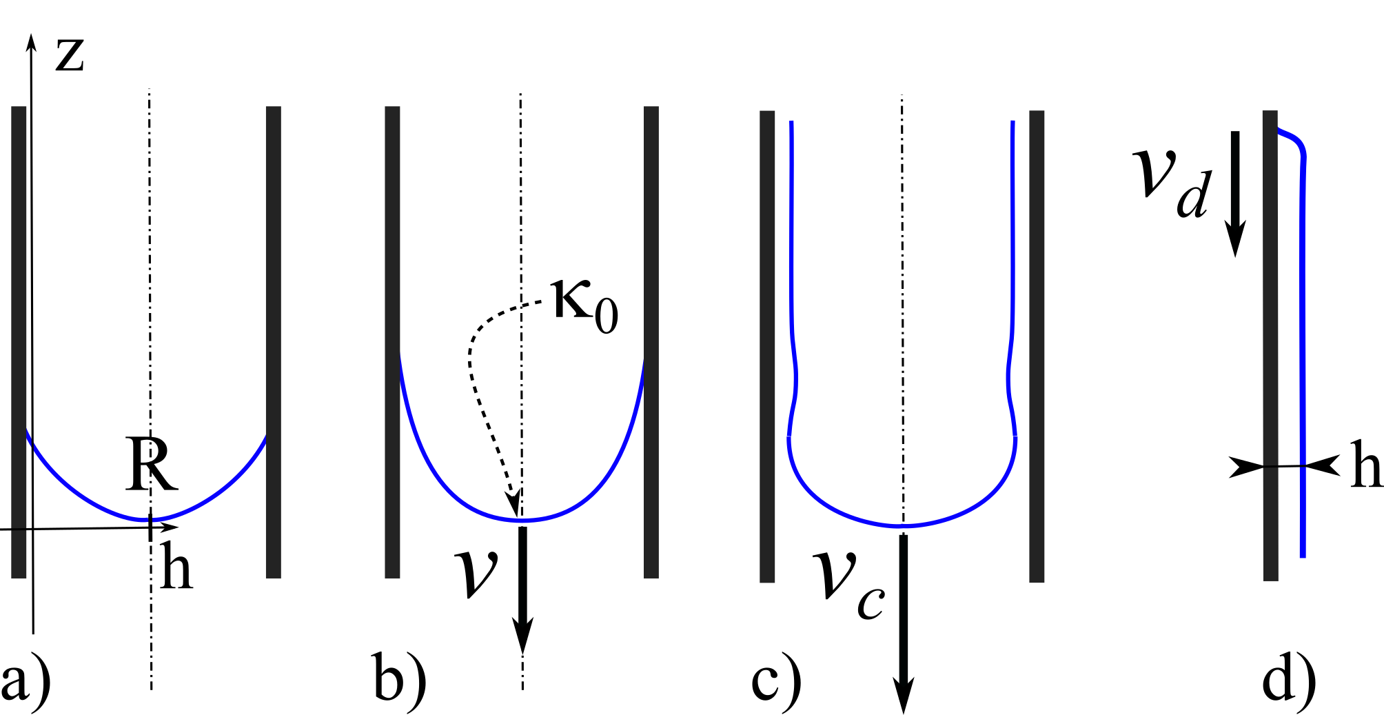
For partially wetting liquids, with non zero static contact angle (Fig. 1 a), the dynamics is noticeably more complex. When the substrate is pulled out of the liquid bath, hydrodynamic dissipation appears in the triple line region. At the macroscopic scale, the dynamic meniscus adopts an elongated shape and its contact angle decreases with velocity (Fig. 1 b) [4, 5, 6]. Above a critical velocity , a dynamic meniscus with a steady state triple line is no longer stable and a liquid film is entrained (Fig. 1 c). This destabilization of the dynamic meniscus, also called dynamic wetting transition, occurs at a critical capillary number which depends on the equilibrium contact angle and is typically of the order of to [7, 8, 9]. The concept of an intrinsic maximum dewetting velocity for the triple line has often been invoked to explain the transition from dynamic meniscus to film [10, 7]. However, a more recent theoretical investigation of triple line dynamics based on lubrication theory proposed a different picture: beyond a critical velocity, the dynamic meniscus profile can no longer be matched to the static meniscus curvature [11, 12]. The critical velocity depends not only on the triple line dynamics but also on the macroscopic geometry. This prediction has to date not been validated experimentally.
Despite these complexities, film thicknesses for partially wetting liquids are expected to follow a very simple relation. Dewetting with velocity feeds the film at the top contact line (Fig. 1 d), and the flux must match gravity driven drainage, with flux , resulting in a steady state, homogeneous film with thickness
| (1) |
a result first predicted by Derjaguin [2]. However, Hocking [13] and Snoeijer [8] have shown that within the lubrication approximation, given the triple line constitutive relation [14, 15, 16, 4], there is only one permitted value of triple line velocity (or capillary number ). As a result, for a partially wetting fluid, when a film forms, its thickness is unique and independent of the pull-out velocity . This simple but somewhat non-intuitive theoretical prediction has been confirmed numerically [17] and experimentally by dip-coating silicone oils on fluorinated flat plates [18, 19] (with viscosities in the Pa.s-1 range and Ca). However, the details of the forced wetting transition and how the dynamic triple line evolves into the film deposition regime remain unclear [8].
Here, we investigate film thickness selection for dewetting liquids with much lower viscosities, namely aqueous solutions on hydrophobic surfaces. To easily exceed the cm/s threshold velocity required for dynamic wetting, we drive aqueous bridges inside vertical polymeric tubes by application of pressure in a cylindrical geometry. To better understand the detailed morphology of the deposited films and how it evolves with time, we have developed an original experimental method. The resulting snapshots of deposited films reveal uniform thicknesses, but in contrast to previous results, we find that we can select the thickness of the steady state films. We show that the film thickness and the triple line dynamics are still strongly interconnected, but that they can both be selected through the macroscopic curvature of the meniscus at the dynamic wetting transition. Thus, this thickness selection mechanism directly evidences the coupling between macroscopic meniscus geometry and meniscus stability advocated by Eggers [12]. Conversely, it also points to more complex mechanisms for adjusting triple line dynamics to different film thicknesses at high capillary numbers.
II Experiments


Fast dewetting experiments were performed in vertical tubes with 1.5 meter length and 6.4 mm inner diameter. The tube material was plasticized polyvinylchloride (Tygon, Saint-Gobain). A 2 mL bridge of liquid was introduced at the top of the tube. Subsequently, pressurized nitrogen was allowed at the top so that the liquid bridge, which was initially at rest, reached a stationary velocity within a transient time negligible compared to the total measurement duration. For low velocity experiments, a similar setup, smaller in size, was also used. This allowed to index match the outside of the tube in a containing cell with parallel faces for better optical observations. Steady state velocities ranged between and 1 m.s-1 for overpressures of the order of tens of Pa.
We used solutions of glycerol in water with mass fractions ranging from 0 to 75 wt%. Viscosity increased from 0.94 to 30 mPa.s and surface tension decreased from 70.3 to 59.0 mN.m-1 with glycerol addition. With these combinations of surface tensions and viscosities, the capillary length was nearly constant, varying from 2.66 mm to 2.25 mm, close to the tube radius =3.2 mm, while the characteristic velocities of the liquids, defined as , ranged from 2 to 75 m.s-1.
Quantitative absorption imaging provided snapshots of film thickness profiles over a 40 cm field of view along the tube. To that end, mol.L-1 New Coccine, a red dye, was added to the liquids. This dye was selected so that viscosity, surface tension, and interfacial tension were not affected, and no adsorption nor absorption of the dye was detected after prolonged contact with the tubes. A white LED screen provided backlight illumination and green-filtered images (10 nm bandwidth, 508 nm central wavelength for maximum absorption) were collected with a camera. Absorbance was calibrated against precision rectangular cells with 10 to 800 m thickness. Images were captured at frame rates between 5 and 1000 Hz. Intensity from the vertical middle section was converted into film thickness by the Beer-Lambert law where is the transmitted light intensity, is the intensity transmitted through a non absorbing water film, L.mol-1cm-1 is the measured extinction coefficient and is the dye concentration. This method provided instantaneous profiles of film thickness with a 5 m accuracy. It improves over most tube experiments reported in the literature, where homogeneous and constant film thicknesses are assumed and evaluated as averages based on mass conservation [20, 21]. A few experiments were carried out at a lower dye concentration so that an image of the full meniscus shape could be recorded to evaluate the variation of its curvature.
III Results
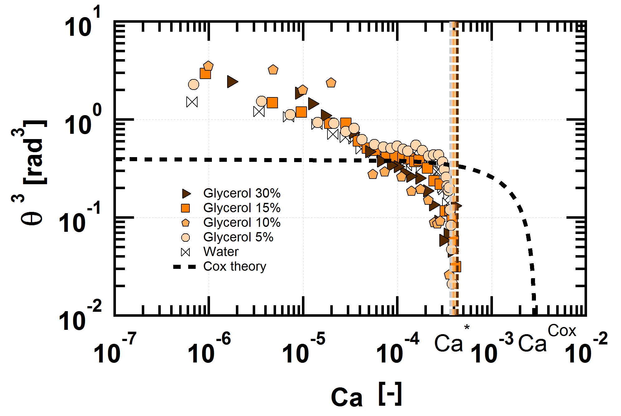
The macroscopic receding contact angles of the dynamic meniscus were measured at low velocities (Fig. 2). For all the fluids we observe an initial decrease of the receding contact angle followed, despite some significant scatter in the data, by a more or less extensive plateau-like behaviour with a dynamic contact angle approximately equal to 40∘. This plateau is followed by an abrupt decrease and tends to zero for . The data are compared to the Cox-Voinov prediction for a receding triple line
| (2) |
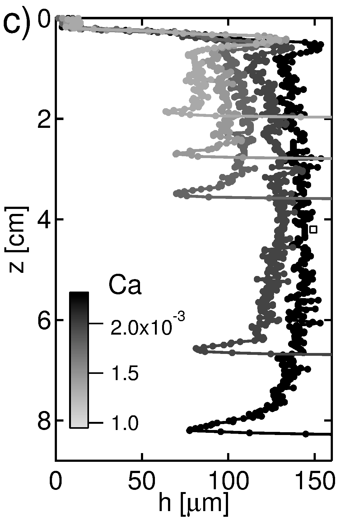
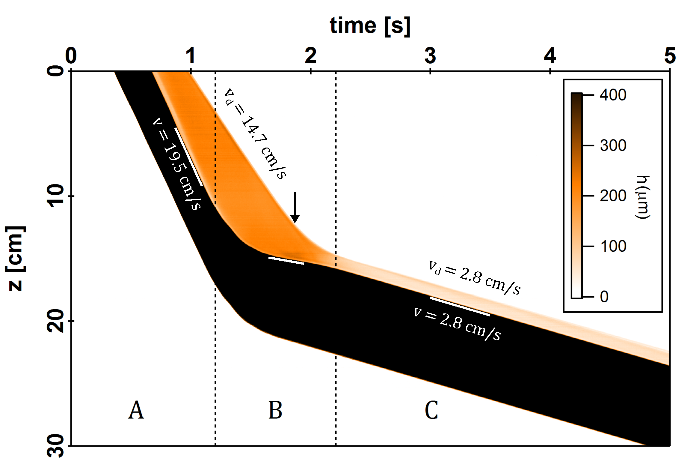
where is the equilibrium contact angle and and are the upper and lower cut-off lengths, with . Setting in Eq. 2, the plateau is fitted to the Cox-Voinov law (dashed line) which is found to overestimate since forced wetting is predicted to occur for , one order of magnitude larger than measured. Note that there is an intermediate velocity range between and (Fig. 2 - dashed area) where 20 cm long tube segments are too short to establish a steady state regime with confidence, because the characteristic times of the transients become increasingly large). In fact, using the long tubes, for all the liquids tested, forced wetting is observed above and a liquid film forms almost instantaneously (Fig. 3b). Space-time plots of film profiles are built from image series (Figure 3c). The dark area corresponds to the liquid bridge, the orange area marks the presence of the liquid film and the white area is the bare tube. Three thickness profiles at different times are also plotted in Fig. 3c (inset). For series of snapshots, the rear meniscus velocity and the contact line velocity could be measured precisely (Fig. 3a, c).
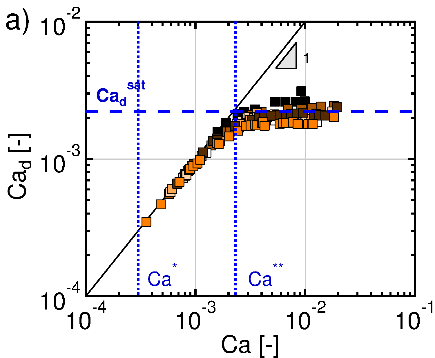
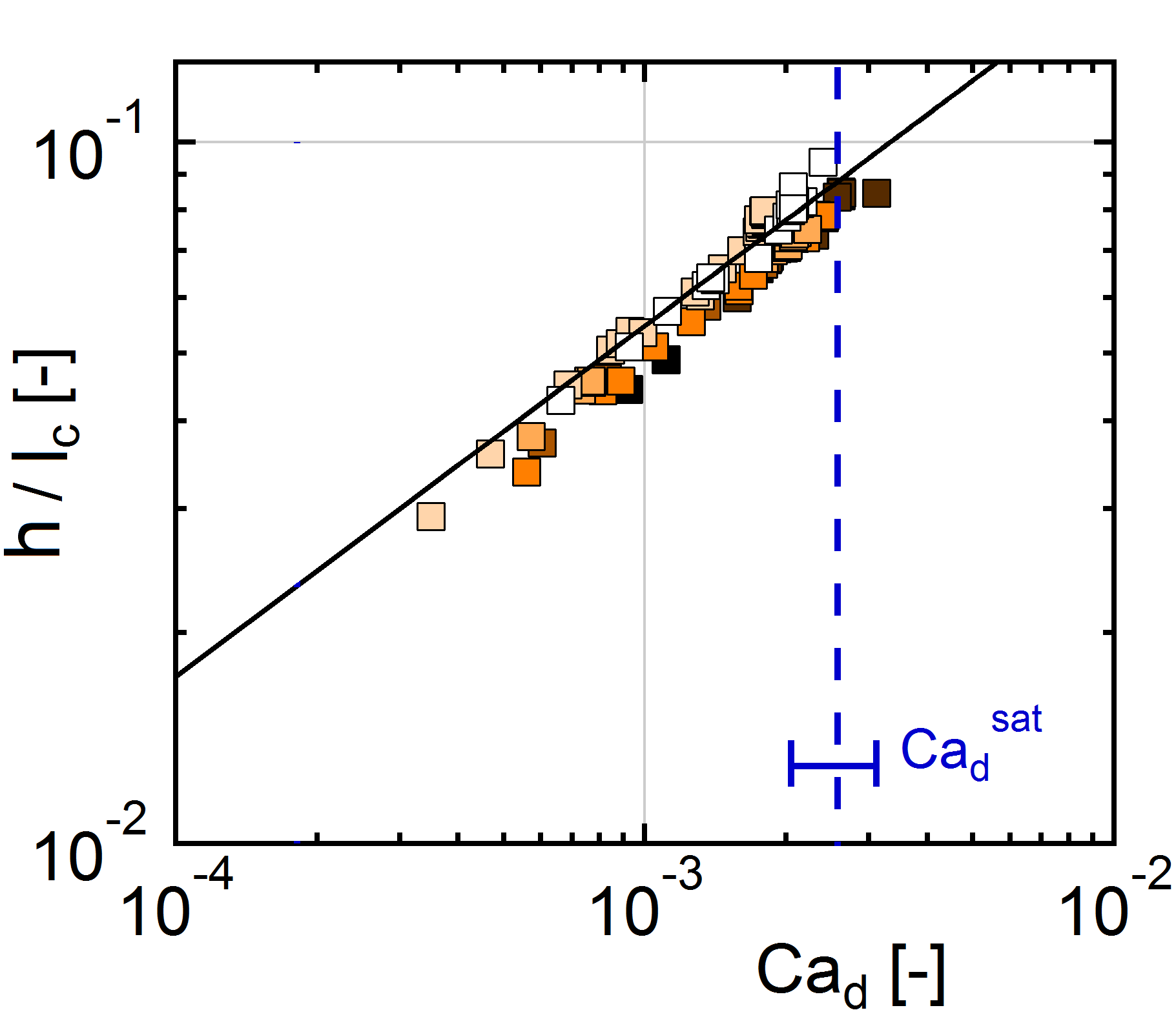
We observe that the film profiles exhibit a nearly uniform thickness, and that this thickness stays constant over time (Fig. 3b, c). Important additional features are what appears to be a shallow rim at the top and a dimple at the junction with the meniscus (Fig. 4c). The dewetting velocity at the triple line is slightly smaller than the meniscus velocity so that the film slowly grows in length at constant thickness. These results clearly show that the flows at both ends of the film are steady state (Fig. 3a) but as anticipated by Hocking [13], the capillary number at the triple line is slightly smaller than the capillary number of the meniscus . Figure 4a shows that for , and for various liquids and forcing conditions, and are related by a slightly sublinear relation until a second threshold denoted is reached. This upper limit will be explained in more detail in the discussion. The measured film thickness , normalized by capillary length , is plotted as a function of in Fig. 4b over the same range.
The remarkable result, which contrasts with other observations in the literature [18], is that the film thickness varies significantly, over one order of magnitude. The Derjaguin relation between and Eq. 1 is plotted in Fig. 4b with no adjustable parameter and the agreement is excellent. The LLD relation was tested against the data: does not follow a law. This result suggests that the steady state film thickness is controlled by dewetting at the top of the film, as expected from [13, 18], and not by the dynamic meniscus at the bottom, as it would be in the LLD regime. This decoupling between film and meniscus was further tested through more elaborate experiments. After dynamic film formation at a given (Fig. 5, zone A), we swiftly decrease pressure. The bridge slows down precipitously (zone B) and finds a new steady state velocity (zone C). We observe no concomitant variation of film thickness or dewetting velocity until the film, which now recedes much faster than the meniscus, has shrunk to a new equilibrium. Such transients clearly demonstrate the capacity of the film-meniscus junction to accommodate a set film thickness at different velocities, so that is independent of . We conclude that triple line velocity and meniscus velocity are decoupled, since once the triple line velocity has been set, it is retained afterwards, also setting the film thickness.
However, we also find that we can select the velocity and thickness, in contrast to previous results [13, 18]. Therefore, this selection mechanism can only operate at film birth, i.e. upon destabilization of the dynamic meniscus. To better understand this process, we now numerically investigate the stability of dynamic menisci in tubes, i. e. we explore the nature of steady state solutions as a function of both velocity and applied pressure, as well as the conditions under which solutions with triple lines exist.
IV Model
We calculate steady state profiles for an axisymmetric, dynamic meniscus moving down a vertical tube in the presence of gravity, with the geometry shown in Fig. 1 b. The notable difference between a plate and a tube is that for the tube the applied pressure sets the macroscopic meniscus curvature . Thus pressure enters the calculations as the curvature boundary condition on the symmetry axis. As will be shown in detail below, depending on pressure, three types of solution may appear, which are shown in Fig. 6. The end point of the profile may lie at the inner surface of the tube (), in which case we have a dynamic meniscus with triple line. Another possible case is a profile which does not touch the tube surface but curves back into the liquid, thus forming a Bretherton-type bubble [23]. Finally, at the boundary between these two cases, we find a limit case where the liquid surface ends up parallel to the tube wall at large positive values, i.e. a liquid film.
More precisely, within the standard model, using the lubrication approximation [11, 22], in the meniscus frame, the profile obeys
| (3) |
where surface curvature is given by
| (4) |
In Eq. 4, the second term characterizes the axisymmetric geometry and is e.g. responsible for the Plateau instability of liquid columns.
The constant cte in Eq. 3 is set by the incoming flux: because we model a steady state triple line (Fig. 1 b), the total flux is zero and . To handle the triple line singularity, we introduce a small slip length which is taken equal to unless otherwise noted.
Note also that Eq. 3 is a third order differential equation. We shoot from bottom of the meniscus, at on the symmetry axis. the boundary conditions are initial thickness (), slope () and curvature (given by ). If the solution meets the tube ( for some positive ), then there is a triple line. If not, the solution is a bubble. Note that in this numerical scheme, the microscopic contact angle is not yet a boundary condition: it is result of the calculation, and a function of the parameters , and . We can of course prescribe a microscopic contact angle, e. g. with a specific constitutive relation specifying the microscopic contact angle as a function of velocity, for a given liquid/surface couple. As will be shown below (Sec. IV.2), with this condition we determine the pressure which has to be applied to obtain a meniscus with steady state velocity .
IV.1 Numerical results
We have computed meniscus profiles for different velocities and pressures for a tube radius , close to our experimental conditions. All spatial dimensions are normalized by including film thickness , vertical coordinate and tube radius which plays the role of a Bond number since . The pressure is normalized by and thus equal to the normalized curvature. The normalized forms of Eqs. 3 and 4 can be found in Appendix A.
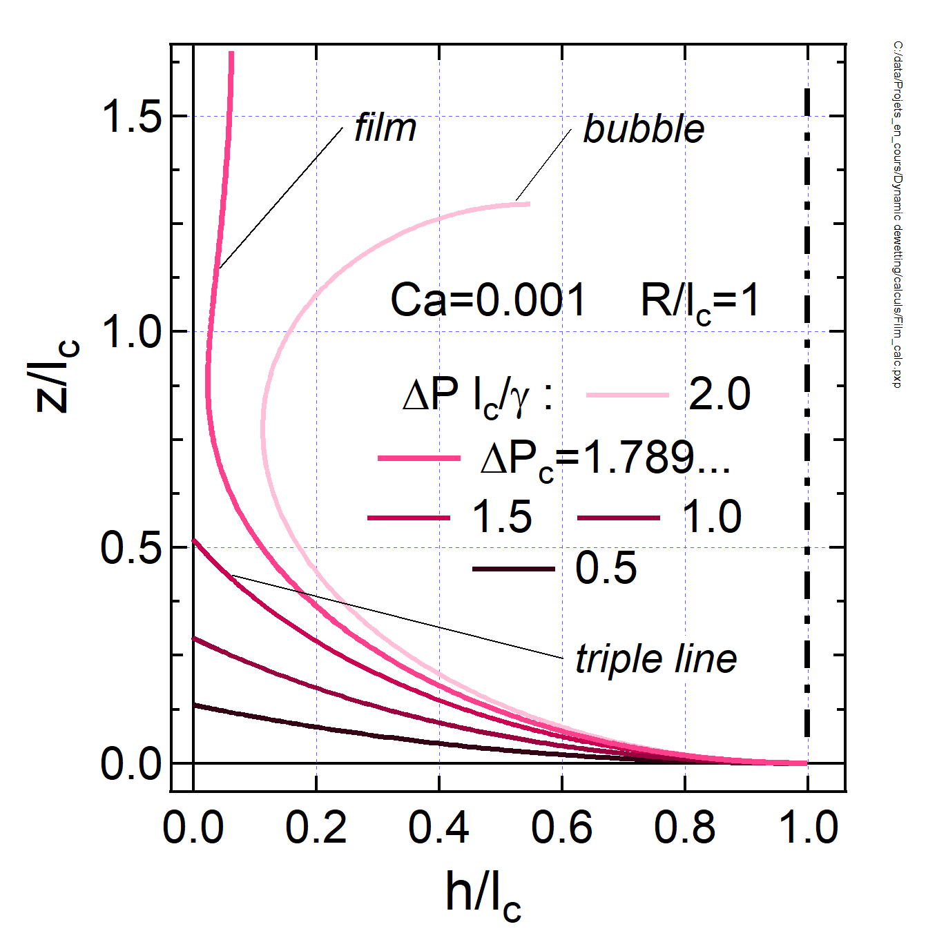
For , several profiles are plotted in Fig. 6 for increasing . At low pressures, the curvatures are small and the profiles meet the tube wall thereby forming a dynamic triple line with a microscopic contact angle defined by where . This microscopic contact angle decreases with increasing pressure (curvature). Because of the low value of the capillary number, the dynamic effects near the triple line are very limited. In particular, variations of the slip length do not elicit significant impact on the profile except for finer details in the immediate vicinity of the triple line (not shown). For higher values of , however, the curvature becomes large enough that the profile no longer meets the surface and we find the bubble solutions of the Bretherton type [23], which are not relevant here. The limit between these two cases, where the dynamic meniscus is matched to a flat (steady state, zero flux) film solution, is obtained for a well defined critical pressure which we now investigate in more detail.
a)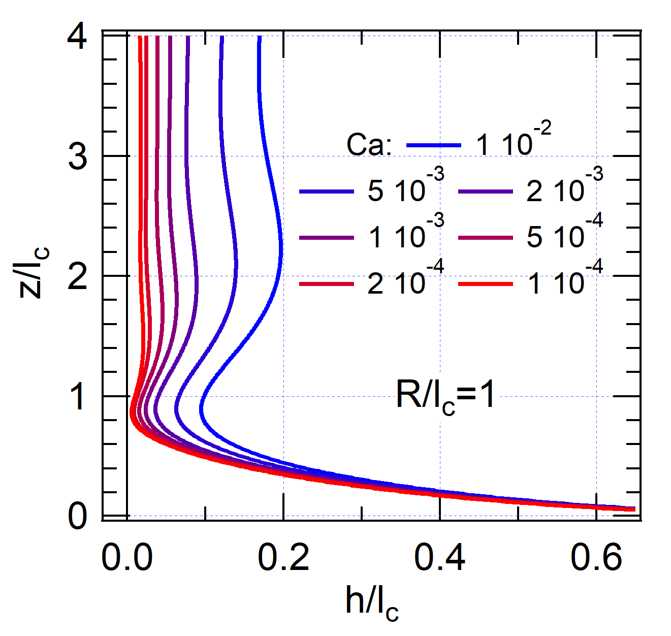 b)
b)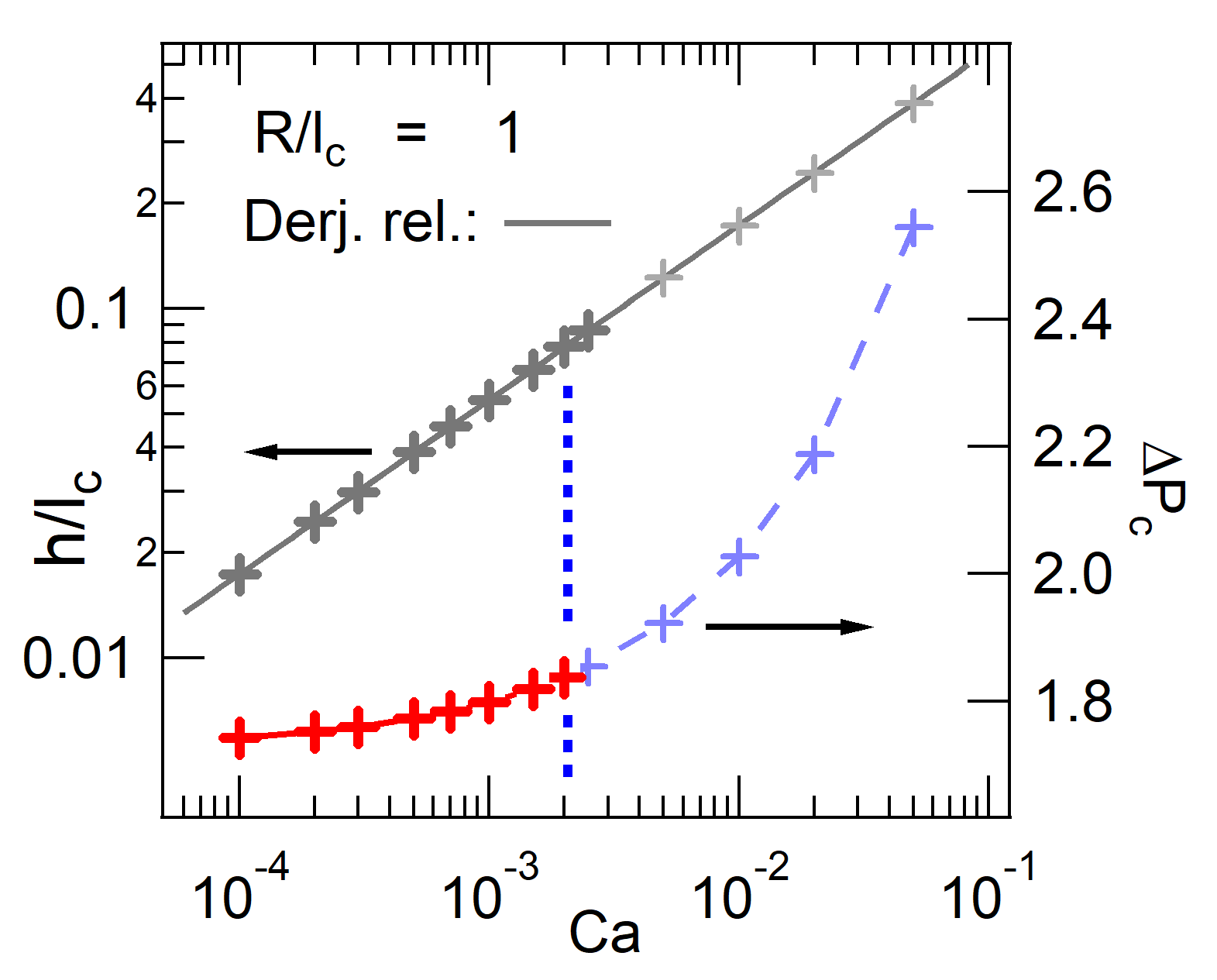
We have computed this critical pressure for different values of velocity , along with the corresponding liquid film profiles (Fig. 7a). The film thickness increases as the velocity increases and the oscillatory nature of the solution becomes more and more apparent. The relation between film thickness and is plotted in Fig. 7b (left hand axis): it obeys Eq. 1 with no adjustable parameter. This is no surprise since by definition of the triple line, we impose a zero flux condition as the film forms. With this and a flat film, Eq. 3 simplifies into Eq. 1. The relation between critical pressure and is plotted in Fig. 7b (right hand axis). We find a definite variation of the critical pressure with velocity, although it remains moderate in the range which is of primary interest in our experiments. In particular, converges to a finite value as the velocity goes to zero. These results evidence how the mechanism for film thickness selection is related to macroscopic curvature and pressure.
In the experiments, this impact of pressure can also be observed directly on the images. Some snapshots were taken with a lower dye concentration: the film thickness can no longer be measured but the full meniscus profile is now visible. Five profiles for different velocities ranging from to slightly above are shown in Fig. 8 a) along with numerical solutions of Eq. 3 (dashed lines). Despite slight asymmetries due to some distortion in the lighting pattern, for the 3 intermediate velocities, we find that the observed meniscus shapes are consistent with the numerical predictions. The agreement between predicted and observed meniscus shapes is not as good when the film has not developed (e.g. lowest velocity shown), or when has been exceeded. In this case, which is the highest velocity shown, the meniscus snapshot is no longer axisymmetric. Neither situation is accounted for in the model.
a) 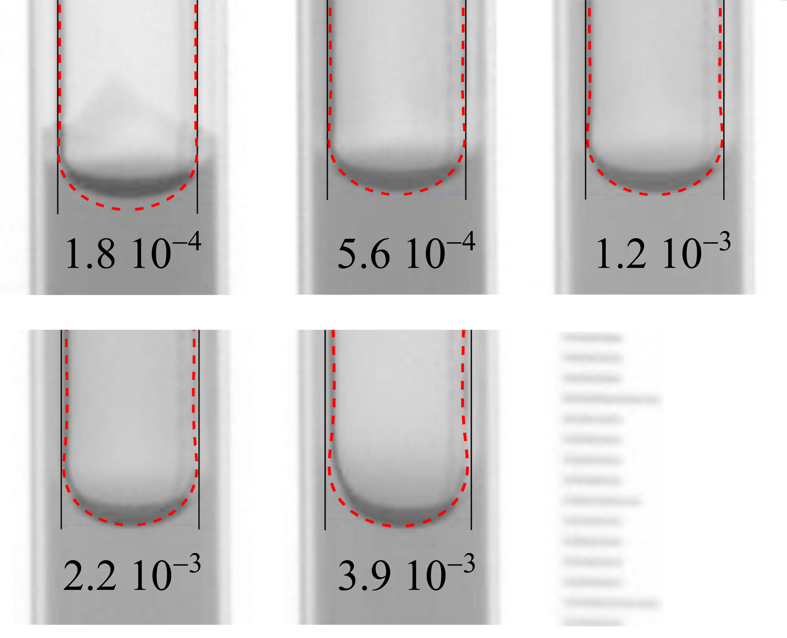 b)
b) 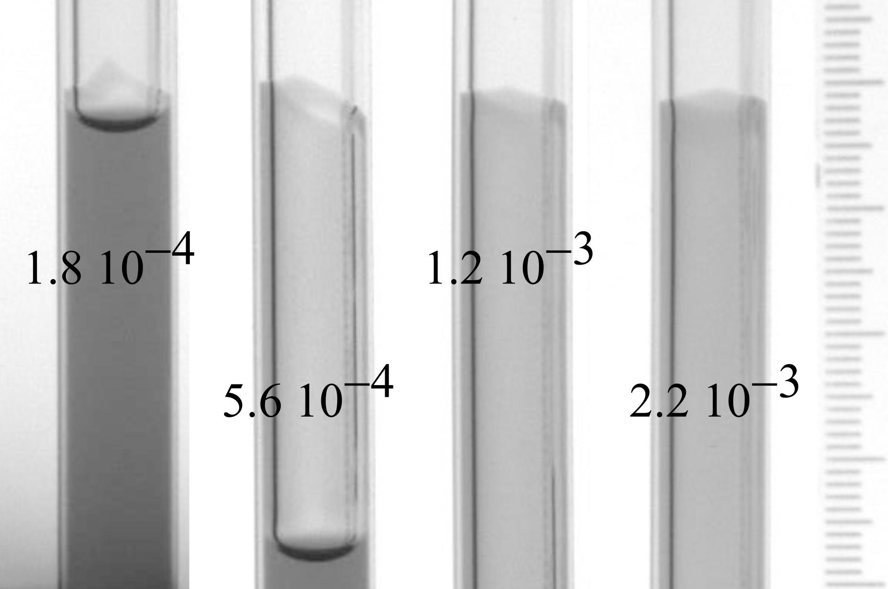
a)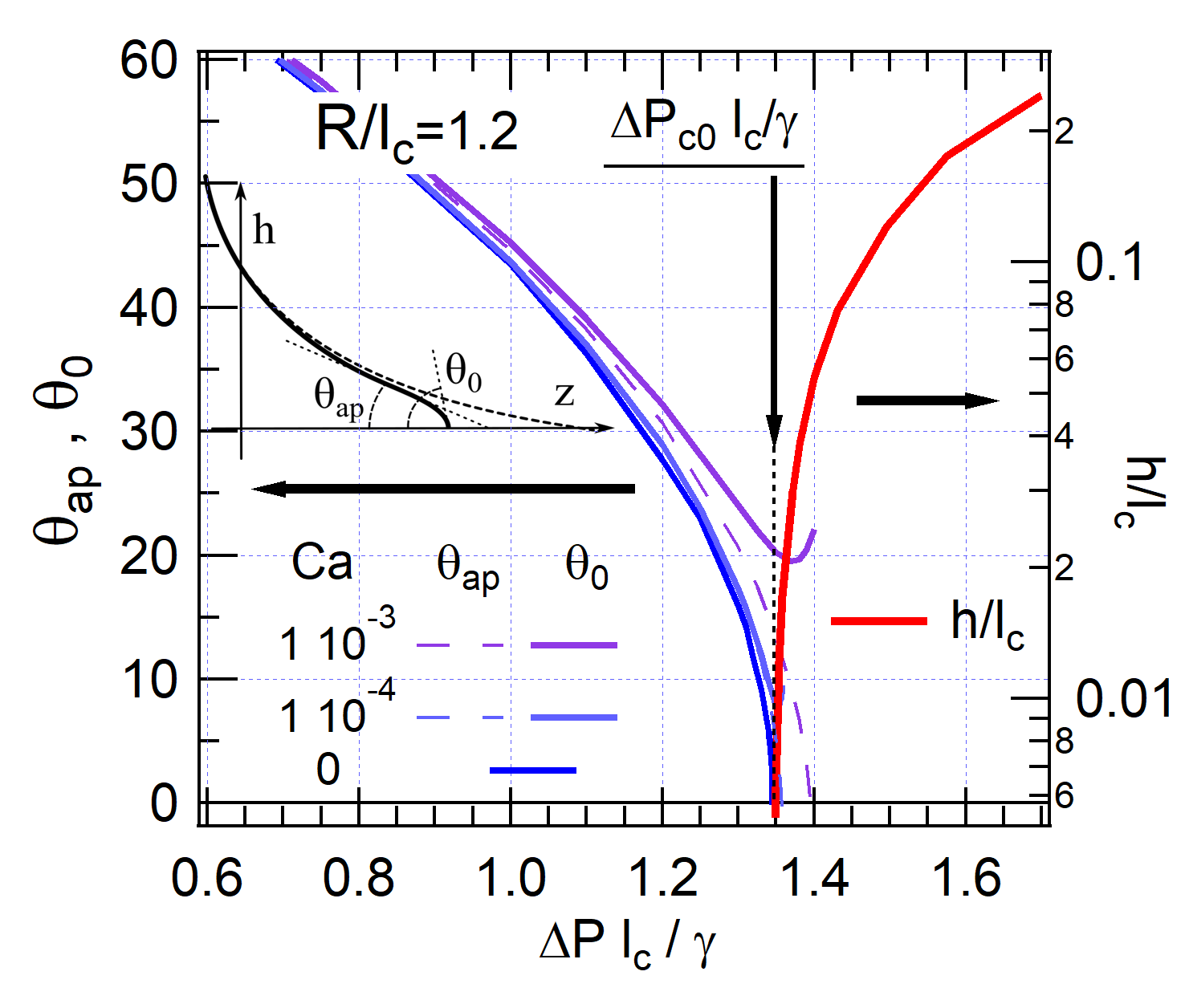 b)
b)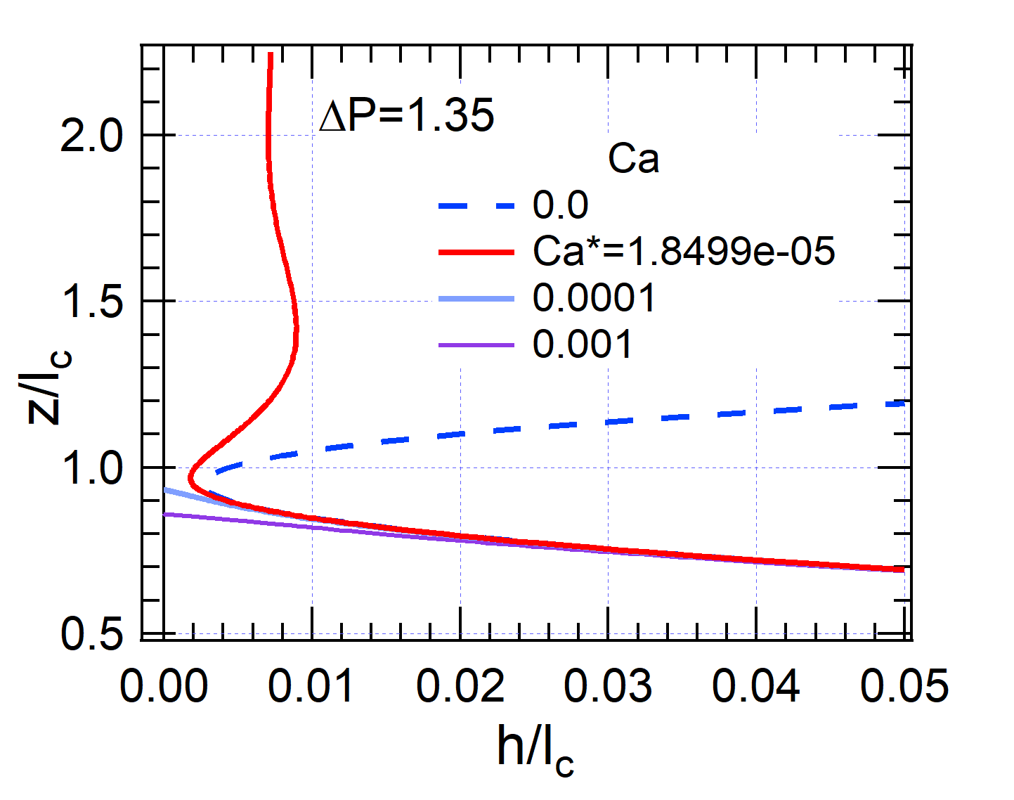
IV.2 Building up a phase diagram
Intriguingly, the model seems to predict that arbitrarily thin films can be obtained: this would simply require a pressure just exceeding the threshold (Fig. 7b). In the experiments, in contrast, there is a lower bound to the film thickness and this limit is directly related to , the velocity of the dynamic wetting transition (Fig. 2). To clarify the role of this threshold, we now consider the stability of the dynamic meniscus, keeping in mind its dynamical properties as reflected in Fig. 2.
Taking a constant radius , we map out the space (, ) of the solutions to Eq. 3. To explore this family of solutions, we first plot the microscopic contact angle for static solutions () (Fig. 9 a - blue line). With increasing macroscopic meniscus curvature , the microscopic contact angle decreases from 90∘ at to 0∘ at . If is non zero, the triple line becomes dynamic, viscous bending sets in (Fig. 9 a - inset) and for the same the microscopic contact angle is now larger than the static microscopic contact angle. However, the difference between microscopic contact angle at finite velocity and static microscopic contact angle is rather small for our typically low values of . It is barely noticeable for (Fig. 9 - light blue line) but becomes clearer at (purple line). Much more significant bending would appear for 10 to 100 times larger . To connect with the macroscopic scale problem, we also define the apparent contact angle which is given by the slope of the liquid profile taken where the dynamic triple line matches the quasi-static meniscus, i.e. at the inflexion point, where the slope is minimum (Fig. 9 a - inset). With this definition, is a good approximation to the experimentally measured contact angle, at the macroscopic scale such as shown in Fig. 2.
To understand our experimental results, we must now consider the specific dynamic behaviour of the triple line and the constitutive relation between microscopic contact angle and triple line velocity. In many cases, is taken as a constant, resulting in a Cox-Voinov type relation. Experimentally, we have found a more complex evolution of (Fig. 2) which attests to the limited contribution of viscous dissipation at low Ca, due to low viscosity. Other dissipative mechanisms dominate in the present case, which remain elusive. However, as a result, one can neglect the small difference between and and the dependence shown in Fig. 2 would be a good approximation to the constitutive relation. Whatever the dissipative mechanisms, their effect can be represented by a constitutive relation .
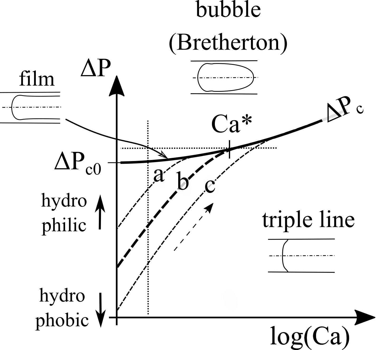
Finally, the (, ) phase diagram (Fig. 10) appears as follows. We find the Bretherton type bubble at high pressures. This state is bounded at low pressures by the line (cf Fig. 7 b) which indicates the conditions under which a film forms. Below this boundary, we find the solutions with a dynamic meniscus and a triple line. Because for these solutions each point in the (, ) phase diagram corresponds to a given contact angle, which can be calculated, specifying a constitutive relation restricts the family of solutions to a curve in this part of the phase diagram. We have schematically shown three such curves (dashed lines in Fig. 10). Starting from zero velocity, where the static contact angle is obtained at a finite pressure (this is capillary rise), the meniscus state follows the curve as velocity increases. For a more hydrophilic surface (curve a), the microscopic contact angle is smaller, so less viscous bending (and so a lower velocity) is required to reach equilibrium at the same pressure: the curve is shifted to the left. Conversely, for a more hydrophobic surface, the path shifts to the right (curve c). The precise path of course depends upon the details of but the phenomenology and the physics remain the same whatever the details of the dissipation mechanisms.
Nota that the line, which marks the appearance of the thin film, does not depend upon the constitutive relation of the triple line since the liquid surface does not meet the solid. However, the dynamic meniscus becomes unstable and a spreading thin film appears when, for a given liquid surface couple, the curve meets the line. This will occur at the finite velocity and result in the corresponding finite film thickness. Thus, in the pressure range , the dynamic meniscus solution is stable. The corresponding range of film thickness is inaccessible. As a further example, a series of solutions calculated at fixed pressure slightly above for different values of is shown in Fig. 9b. The static solution is bubble-like and not relevant for our boundary conditions. A finite velocity is required with enough viscous bending to meet the surface. In fact, at the threshold velocity , a zero flux film forms. For , the dynamic meniscus has a triple line.
Thus, although the relation between pressure and film thickness does not depend upon the liquid/surface properties, the threshold value does [13, 24]. In the experiments, preliminary tests were carried out with the same liquids and in tubes identical in geometry but made of polydimethylsiloxane (PDMS). The results demonstrate a similar phenomenology but with , a ten fold increase which is easily rationalised by the more hydrophobic nature of PDMS (). However, because these tubes are not optically clear, more advanced evaluations could not be carried out.
V Discussion
We have given a detailed account of the impact of pressure on the stability of the dynamic meniscus in a tube. At low pressures, the meniscus curvature is low enough and a suitable velocity can be found to ensure that local contact angle dynamics and equilibrium equations are obeyed simultaneously. For larger pressures, and the triple line is unstable so that when pressure is applied, a thin film forms almost instantaneously. Its thickness depends upon the meniscus curvature as shown in Fig. 7 b. Pressure is a control parameter from which film thickness can be adjusted (Fig. 4). A significant range of steady state film thicknesses can be selected, in contrast to previous results [13, 8] where a unique film thickness was selected, dependent on the uniquely valued at the forced wetting transition. The lowest accessible thickness (and thus the critical capillary number ) depends upon the liquid surface properties.
Once formed, the film adopts a given thickness but it can adapt to a range of meniscus velocities, as shown in Fig. 5. Indeed, within the lubrication approximation, Wilson and Jones [25] have shown how, due to the gravity driven downward flow, the film matches to the meniscus through two oscillatory solutions with one phase-like free parameter. With this additional variable, different meniscus velocities can be accommodated by the same film thickness. Interestingly, the oscillatory nature of the predicted profiles is directly reflected in the dimple we observe at the junction between film and meniscus (Fig. 4 c). In contrast, in the Landau Levich solution, there is no gravity driven flow, and there is a single solution of exponential type. In fact, in our case, when the velocity is too large, the downward, gravity driven flux becomes too small and the steady state solution switches to a Landau-Levich, single exponential, type. This transition marks the upper limit to the regime of interest here and the threshold velocity is the upper bound mentioned earlier.
We now turn to the relation between the film and its own triple line, at the top. Because the steady state differential equation is of third order, while there are two oscillatory solutions at the bottom, there is a single exponential-like solution at the top to match the film to the triple line. It is this structure of the solution which explains why, given the local dynamics of dewetting , the drainage of a film fed by a dewetting front at its top leads to a unique thickness value and unique receding triple line velocity, as discussed earlier [13, 8].
Surprisingly, in our case, we find that the triple line at the top of the film can accommodate a range of dewetting velocities which are actually selected by the applied pressure as the film emerges from the unstable meniscus. We do not have a definite explanation for this observation, but we can point out a few features of the triple line of the film which do not belong to the standard description [13, 8]. First we observe a (rather flat) steady state rim which does not belong to the standard model. Also, the triple line is usually not straight but has an undulating profile and may even sometimes exhibit angular features (Fig. 8 b). Modulations of the shape of the triple line and especially such angular features are indeed known to regulate dewetting speeds above the entrainment threshold [10, 26, 27] while line front modulations accelerate the relaxation dynamics [28]. Therefore, although the exact mechanism is not clear, we suspect that it is such additional dynamic phenomena connected to modulation of the contact line profile which stabilize the film thickness.
VI Conclusion
In conclusion, we have investigated the dynamic wetting transition for partially wetting liquids inside tubes. With this geometry, we can reach relatively high velocities and thus use low viscosity fluids. In addition, using absorption imaging, we can accurately follow the thin film geometry and dynamics at high speed. Our observations of the dynamic wetting transition and the geometrical and dynamic characteristics of the liquid film mostly conform to standard models. However, in place of the unique film solution predicted and reported in the literature, we find that we can select the film thickness within a well identified range. The selection operates immediately upon destabilization of the dynamic meniscus. It is mediated by the pressure induced meniscus curvature, thus providing a direct experimental demonstration of the effect of macroscopic geometry on the stability of a dynamic meniscus. The critical capillary number above which a film forms (and thus the lowest accessible thickness) depends upon the liquid/surface properties. The film thickness is directly related to the velocity of the dewetting triple line at the top of the film as expected from the Derjaguin relation. However, the very fact that the film thickness is not unique, but can be tuned over almost a decade, does not conform to the standard model. This observation implies a more complex dynamics for the triple line which may arise from its undulating morphology at the macroscopic scale, a feature which stands at variance with the standard assumption of a straight front. This high velocity dynamics of the triple line certainly deserves further studies.
Acknowledgements.
We thank Ludovic Olanier for help with the experimental set-up and Arnaud Antkowiak, Terry Blake, Marc Fermigier, Laurent Limat, David Quéré, Etienne Reyssat and Jacco Snoeijer for fruitful discussions and suggestions.References
- [1] L. D. Landau and B. V. Levich. Dragging of a Liquid by a Moving Plate. Acta Physicochim. URSS, 17:42, 1942.
- [2] B. V. Derjaguin. Thickness of liquid layer adhering to walls of vessels on their emptying. Acta Physicochim URSS, 20:349, 1943.
- [3] KJ Ruschak. Coating flows. Annual Review of Fluid Mechanics, 17(1):65–89, 1985.
- [4] D. Bonn, J. Eggers, J. Indekeu, J. Meunier, and E. Rolley. Wetting and spreading. Reviews of Modern Physics, 81(2):739, 2009.
- [5] J. H. Snoeijer and B. Andreotti. Moving contact lines: Scales, regimes, and dynamical transitions. Annual Review of Fluid Mechanics, 45:269–292, 2013.
- [6] E. Rio and F. Boulogne. Withdrawing a solid from a bath: How much liquid is coated? Advances in Colloid and Interface science, 247:100–114, 2017.
- [7] J. G. Petrov and R. V. Sedev. On the existence of a maximum speed of wetting. Colloids and Surfaces, 13:313–322, 1985.
- [8] J. H. Snoeijer, G. Delon, M. Fermigier, and B. Andreotti. Avoided critical behavior in dynamically forced wetting. Physical Review Letters, 96(17):174504, 2006.
- [9] B. Zhao, A. A. Pahlavan, L. Cueto-Felgueroso, and R. Juanes. Forced wetting transition and bubble pinch-off in a capillary tube. Physical Review Letters, 120(8):084501, 2018.
- [10] T. D. Blake and K. J. Ruschak. A maximum speed of wetting. Nature, 282(5738):489–491, November 1979.
- [11] O. V. Voinov. Wetting: inverse dynamic problem and equations for microscopic parameters. Journal of Colloid and Interface Science, 226(1):5–15, 2000.
- [12] J. Eggers. Hydrodynamic theory of forced dewetting. Physical Review Letters, 93(9):094502, 2004.
- [13] L. M. Hocking. Meniscus draw-up and draining. European Journal of Applied Mathematics, 12(03):195–208, 2001.
- [14] T. D. Blake and J. M. Haynes. Kinetics of liquidliquid displacement. Journal of Colloid and Interface Science, 30(3):421–423, 1969.
- [15] OV Voinov. Hydrodynamics of wetting. Fluid Dynamics, 11(5):714–721, 1976.
- [16] R. G. Cox. The dynamics of the spreading of liquids on a solid surface. Part 1. Viscous flow. Journal of Fluid Mechanics, 168:169–194, 1986.
- [17] P. Gao, L. Li, J. Feng, H. Ding, and X. Lu. Film deposition and transition on a partially wetting plate in dip coating. Journal of Fluid Mechanics, 791:358–383, 2016.
- [18] J. H. Snoeijer, J. Ziegler, B. Andreotti, M. Fermigier, and J. Eggers. Thick films of viscous fluid coating a plate withdrawn from a liquid reservoir. Physical Review Letters, 100(24):244502, 2008.
- [19] G. Delon, M. Fermigier, J. H. Snoeijer, and B. Andreotti. Relaxation of a dewetting contact line. Part 2. Experiments. Journal of Fluid Mechanics, 604(55):24, 2008.
- [20] P. Aussillous and D. Quéré. Quick deposition of a fluid on the wall of a tube. Physics of Fluids, 12(10):2367–2371, 2000.
- [21] G Callegari, A Calvo, and J.-P. Hulin. Dewetting processes in a cylindrical geometry. The European Physical Journal E, 16(3):283–290, 2005.
- [22] J. Eggers. Toward a description of contact line motion at higher capillary numbers. Physics of Fluids, 16:3491–3494, 2004.
- [23] F. P. Bretherton. The motion of long bubbles in tubes. J. Fluid Mech, 10(2):166–188, 1961.
- [24] J. Eggers. Contact line motion for partially wetting fluids. Physical Review E, 72:061605, 2005.
- [25] S. D. R. Wilson and A. F. Jones. The entry of a falling film into a pool and the air-entrainment problem. Journal of Fluid Mechanics, 128:219–230, 1983.
- [26] T Podgorski, J-M Flesselles, and L Limat. Corners, cusps, and pearls in running drops. Physical Review Letters, 87(3):036102, 2001.
- [27] J. H. Snoeijer, N. Le Grand-Piteira, L. Limat, H. A. Stone, and J. Eggers. Cornered drops and rivulets. Physics of Fluids, 19(4):042104, 2007.
- [28] J. H. Snoeijer, B. Andreotti, G. Delon, and M. Fermigier. Relaxation of a dewetting contact line. Part 1. A full-scale hydrodynamic calculation. Journal of Fluid Mechanics, 579:63–83, 2007.
Appendix A Normalized equations
Appendix B Impact of tube radius
a) b)
b)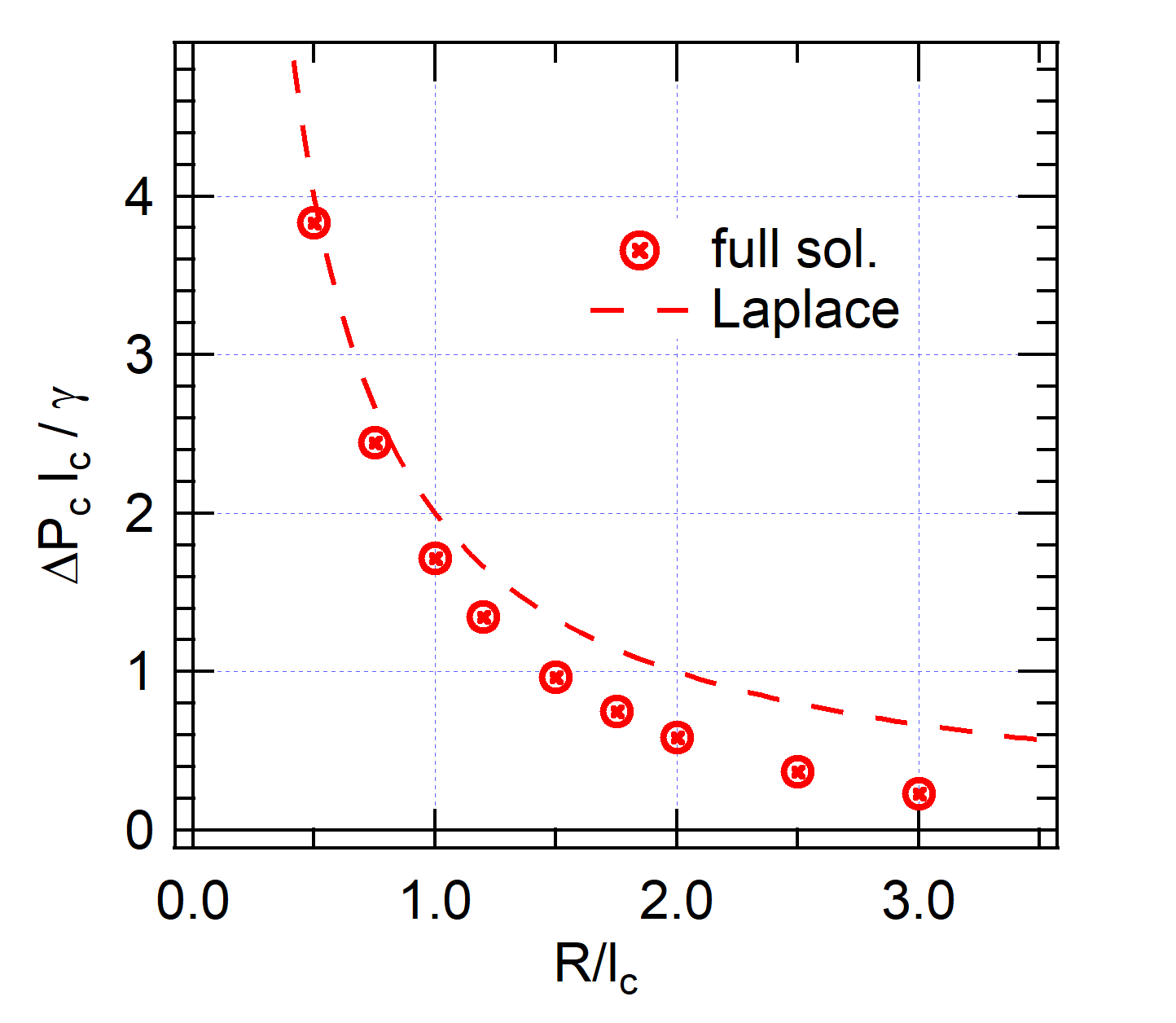
To better understand the role of gravity, the dynamic meniscus calculations were performed for different tube radii (Fig. 11 a). The film thickness is independent of the tube radius, as expected from Eq. 1 but as the tube radius increases, the critical pressure decreases and the pressure variations become weaker. The variations of the critical pressure at zero velocity with tube radius is shown in Fig. 11 b. For , , which is the Laplace pressure. Owing to gravity, drops faster towards 0 when . At larger radii, the flat plate limit is recovered where solutions are pressure independent because they are dominated by the intrinsic, gravity driven, curvature of the profile near the tube surface.