Quantum anomalous Hall effect in metal-bis(dithiolene),
magnetic properties, doping and interfacing graphene
Abstract
The realization of the Quantum anomalous Hall effect (QAHE) in two dimensional (2D) metal organic frameworks (MOFs), (MC4S with M = Mn, Fe, Co, Ru and Rh, has been investigated based on a combination of first-principles calculations and tight binding models. Our results for the magnetic anisotropy energy (MAE) reveal that the out-of-plane (in-plane) magnetization is favored for M = Mn, Fe, and Ru (Co, and Rh). Given the structural symmetry of (MC4S, the QAHE takes place only for M = Mn, Fe and Ru. Such a quantum anomalous Hall phase has been confirmed through the calculation of the Chern number, and examining the formation of topologically protected (metallic) edge states. Further electron (-type) doping of the MOFs has been done in order to place the Fermi level within the non-trivial energy gap; where we find that in (RuC4S, in addition to the up-shift of the Fermi level, the MAE energy increases by 40%. Finally, we show that in MOF/graphene (vdW) interfaces, the Fermi level tunning can be done with an external electric field, which controls the charge transfer at the MOF/graphene interface, giving rise to switchable topologically protected edge currents in MOFs.
I Introduction
Since the theoretical proposal of the quantum spin Hall (QSH) phase in graphene Kane and Mele (2005), the search, as well as the control, of the topological phases in two dimensional (2D) systems has been the subject of intense studies over the past few years. For instance, investigations addressing 2D materials characterized by larger and tuneable (non-trivial) energy gaps mediated by mechanical strain Xu et al. (2013), external electric field perpendicular to the 2D sheet (EEF⟂) Drummond et al. (2012), and/or suitable chemical combinations Padilha et al. (2016). Further studies have been done focusing on the van der Waals (vdW) heterostructures by stacking 2D topological insulators (TI), and combinations of trivial/topological materials Qian et al. (2014).
In a seminal work, Wang et al. Wang et al. (2013a) predicted the quantum anomalous Hall effect (QAHE) in a metal organic framework (MOF) composed by benzene rings attached to three-fold coordinated Mn atoms. Different topological phases have been identified in other MOFs, like the the QSH phase in nickel-bis-dithiolene [(NiC4S] Wang et al. (2013b), synthesized by Kambe et al. Kambe et al. (2013); and the QAHE in manganese-bis-dithiolene [(MnC4S] Zhao et al. (2013). In the latter, the topological phase has been changed from QSH to QAH by replacing the metallic element, NiMn. On the other hand, keeping the transition metal and changing the organic host, recent theoretical studies predicted that (MnC3S6)3 can be tuned from a Chern insulator to Chern half-metal as a function of the Fermi level Wang et al. (2017). In parallel, currently we are facing an amazing progress on the synthesis of 2D metal frameworks Maeda et al. (2016). For instance, the synthesis of metal (M) bis-dicyanobenzenedithiolate with M = Fe, Co, Ni, Pd, Pt, and Zn Alves et al. (2004), which is somewhat similar to the metal bis-dithiolene. Further molecular design has been done by building up multilayered systems by stacking MOFs Colson and Dichtel (2013); Sheberla et al. (2014); Rodriguez-San-Miguel et al. (2016); Sakamoto et al. (2016). Very recently, based on first-principles calculations, we have found that bilayer systems of (MC4S, with M=Ni and Pt, present the Z2-metallic phase, where the edge states can be tuned by an EEF⟂ de Lima et al. (2017).
In contrast with its counterpart, the time-reversal symmetric QSH phase, the breaking of this symmetry by intrinsic magnetization rules the emergence of the QAHE. Such an additional ingredient can be used to control the the electronic properties and the topological phases in 2D systems. Indeed, by tuning the strength of the exchange field, we may have different types of topological gaps and half-metallic phases induced by (intra/inter) spin orbital couplings (SOCs) Hu et al. (2015); Dong et al. (2016). Meanwhile, graphene decorated by 5d transition metals presents a switchable QAHE, where the out-of-plane/in-plane magnetization can be controlled by an EEF⟂ Zhang et al. (2012). Somewhat similar control of the topological phase has been predicted for the triphenyl-lead MOF. At the ground state it is characterized by a (antiferromagnetic) topologically trivial phase, and the QAHE takes place mediated by an EEF⟂, which promotes an out-of-plane ferrimagnetic phase Kim et al. (2016). Very recently, Ren et al. demonstrated that the in-plane magnetization can induce the QAHE in 2D systems with inversion symmetry, and no (out-of-plane) mirror symmetry Ren et al. (2016).
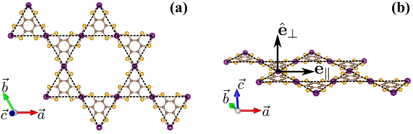
In this work, we use first-principles calculations and tight-binding (TB) models to investigate the electronic and magnetic properties of (MC4S MOFs, with M=Mn, Fe, Co, Ru, and Rh. Fig. 1 shows the structural model of free-standing (MC4S. The energetic preference for in-plane versus out-of-plane magnetization was examined through the calculation of the magnetic anisotropy energy (MAE). We found that the out-of-plane magnetization is favored in (MC4S MOFs with M=Mn, Fe, and Ru, giving rise to (intraspin) energy gap induced by the SOC. The QAHE of those MOFs was characterized by the calculation of the Chern number (), and the formation of topologically protected (metallic) edge states. We show that the Fermi level can be tunned in and out of the non-trivial energy gap with quite feasible electron (-type) doping. Further MAE calculations, on the electron-doped systems, indicate a strengthening of the out-of-plane magnetization in (RuC4S, namely, the MAE increases from 2.0 to 2.8 meV/Ru-atom. Finally, we show that such a -type doping, and consequently the energy position of the Fermi level, can be controlled on MOF/graphene vdW interfaces through an EEF⟂.
II Method
The calculations were performed based on the DFT approach, as implemented in the VASP codeKresse and Furthmüller (1996). The exchange correlation term was described using the GGA functional proposed by Perdew, Burke and Ernzerhof (PBE)Perdew et al. (1996). The Kohn-Sham orbitals are expanded in a plane wave basis set with an energy cutoff of 400 eV. The 2D Brillouin Zone (BZ) is sampled according to the Monkhorst-Pack methodMonkhorst and Pack (1976), using a gamma-centered 441 mesh for atomic structure relaxation and 661 mesh to obtain the self-consistent total charge density. The electron-ion interactions are taken into account using the Projector Augmented Wave (PAW) method Blöchl (1994). All geometries have been relaxed until atomic forces were lower than eV/Å. The metal-organic framework (MOF) monolayer system is simulated considering a vacuum of Å perpendicular to the layers. In order to describe the strong Coulomb interaction between orbitals of the transition metal, we adopted the GGA+U approach Dudarev et al. (1998). In the formation of interface with graphene the vdW interaction (vdW-DF2 Lee et al. (2010)) was considered to correctly describe the system.
III Results and Discussions
III.1 Equilibrium geometry and the MAE
The MOF Metal-Bis(dithiolene) has a hexagonal atomic structure with the metal atoms (M) forming a kagome like structure, indicated by the dashed lines in Fig. 1(a). Here, we have considered M = Mn, Fe, Co, Ru and Rh. The calculated equilibrium lattice constants (), presented in Table 1, matches closely those of the (experimentally synthesized) (NiC4S, where = 14–15 Å Kambe et al. (2013).
In the present (MC4S systems, the QAHE is constrained to an out of plane magnetization of the MOF Ren et al. (2016). The net magnetic moment and its orientation in (MC4S are dictated by the and orbitals of the transition metals; the preferential magnetic orientation was obtained by computing the magnetic anisotropy energy (), here defined as , where and are the total energies of the MOFs with the magnetic moment aligned out-of-plane and in-plane, respectively. It is worth noting that the strongly correlated electrons requires the consideration of the Hubbard correction term. Our results, within the GGA+U approach, of magnetic anisotropy energy () and the net magnetic moment () as a function of the Hubbard U values, summarized in Table 2 in Appendix A, reveals that the stabilization of those magnetic properties is achieved for eV for all studied metals.
The obtained values for the and are shown in Table 1 for eV. We find that (MnC4S presents a net magnetic moment of 3.12 , and easy-axis out-of-plane, meV/Mn-atom, which supports the quantum anomalous phase proposed by Zhao et al. Zhao et al. (2013). The QAHE has been also predicted in graphene adsorbed by transition metals Fe Qiao et al. (2010), Co, Rh Hu et al. (2015), and Ru Acosta et al. (2014). However, in (CoC4S and (RhC4S we found an energetic preference for the in-plane magnetization, meV/Co-atom and meV/Rh-atom, thus indicating that the QAH phase is not expected in those MOFs. Meanwhile, (FeC4S and (RuC4S present FM phases with =0.31 meV/Fe-atom and 2.0 meV/Ru-atom, which points to the emergence of QAH phases in those MOFs.
| MOF | ||||
|---|---|---|---|---|
| (MnC4S | 15.00 | 3.12 | 7.2 | 5.53 |
| (FeC4S | 14.81 | 2.15 | 3.6 | 5.60 |
| (CoC4S | 14.67 | 1.79 | -21.4 | 5.75 |
| (RuC4S | 15.19 | 1.86 | 23.0 | 5.46 |
| (RhC4S | 15.07 | 0.86 | -23.9 | 5.60 |
III.2 Qualitative analysis of the magnetic anisotropy
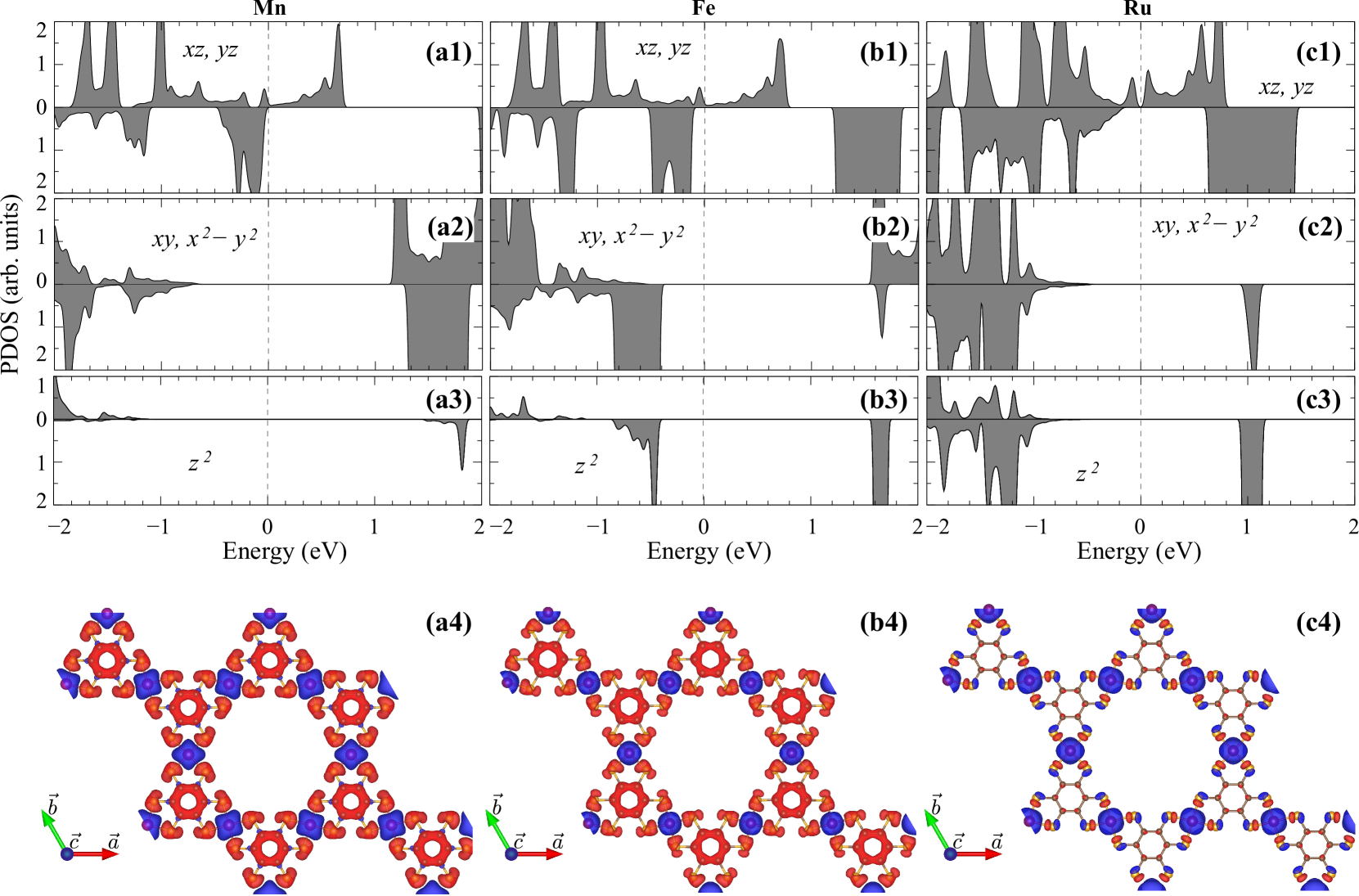
The (MC4S MOFs present a symmetry, giving rise to two sets of doubly degenerated levels at the point, (d and dxy orbitals), and (dxz and dyz orbitals), and a non-degenerated level ( orbital). The projected density of states (PDOS) of these transition metal orbitals, calculated without SOC, are shown in Fig. 2.
The net magnetization of the MOFs is (i) mostly dictated by the orbitals of the the transition metals, where about 50% of the magnetic moment comes from the unpaired orbitals, while the out of plane orbitals contribute with 40% in (RuC4S, followed by (FeC4S and (MnC4S, 30% and 20%, respectively. As a consequence, (ii) the in plane polarization is larger (lower) in the latter (former) system. Those transition metals are embedded in an organic framework, composed C and S atoms, which present opposite net magnetization ruled by the C-2 and S-3 orbitals; such a (opposite) spin polarization is larger (lower) in (MnC4S ((RuC4S). Our spin density results, [Figs. 2(a4)–(c4)], provide a picture of (i) and (ii) discussed above, and allow us to infer that the FM coupling between the transition metals is given by an indirect exchange process, mediated by the organic host of C and S atoms.
The perturbation approach proposed by Wang et al. Wang et al. (1993), allow us to use the PDOS above to provide a qualitative analysis of our MAE resultsSong et al. (2017). There, the is approximately defined by the matrix elements of the orbital angular momentum, i.e. and , where and refer to the orbital component of the wave-function (e.g. ) of the occupied () and empty () states with a given spin , calculated without SOC. Namely, the magnetic anisotropy energy can be written as , where the spin diagonal and non-diagonal terms are
| (1) | ||||
| (2) |
where represents the strength of the SOC. The matrix elements are divided by their (respective) single particle energy difference, indicating that the dominant contributions arise from states near the Fermi level.
For , this model tell us that the is defined by the (dxz and dyz orbitals) orbitals, due to the PDOS peaks near the Fermi level in Figs. 2(a1)–(c1). In these cases, the empty states near the Fermi level are all of the type. Moreover, group theory selection rules dictates that matrix operators between states are null. Therefore the dominant contributions are given by the terms in Eqs. (1)-(2). That is, the sign of is given by the competition between the positive contribution from the spin-diagonal matrix element, and the negative contribution from the spin-flipped terms. For Ru, Fig. 2(c1), there are no contributions near the Fermi level to the PDOS, yielding a large due to the positive spin-diagonal term. For Fe and Mn, Figs. 2(a1)–(b1), the PDOS peaks approach the Fermi level, reducing the .
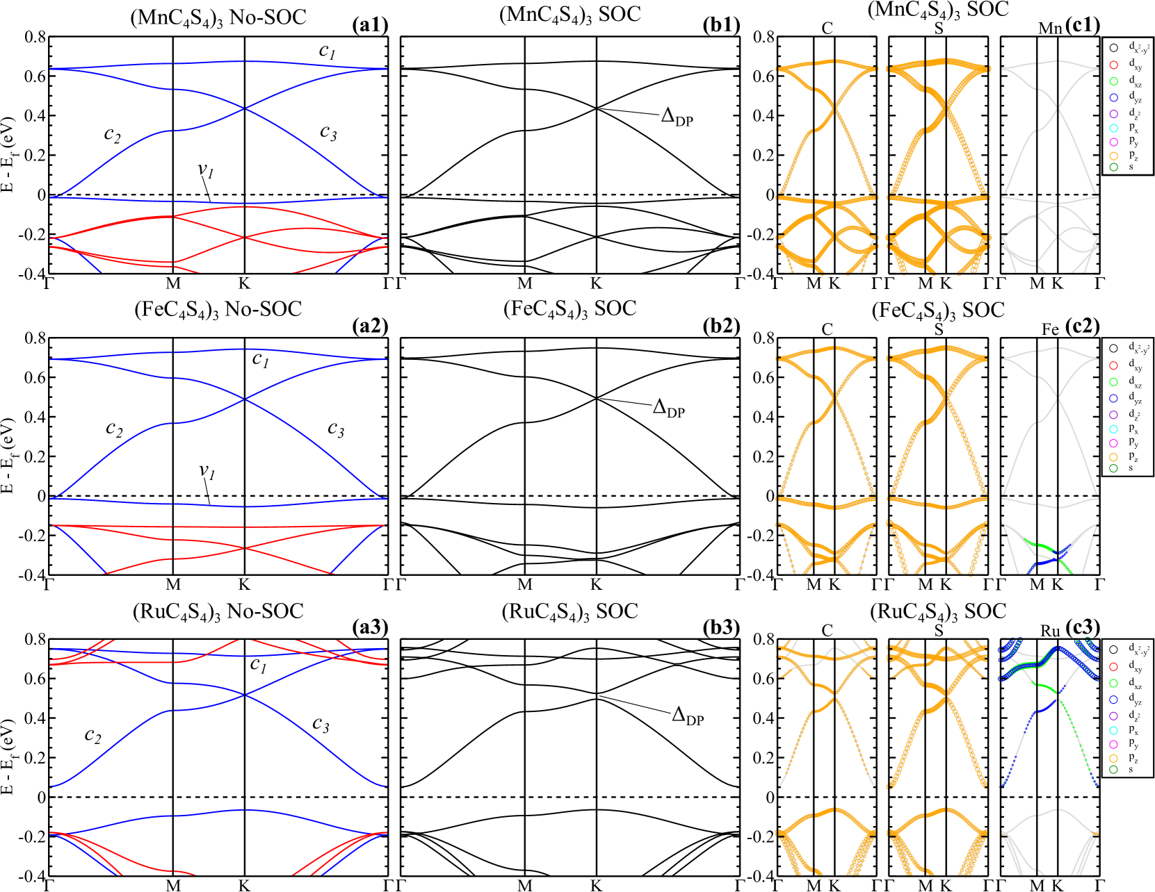
III.3 Kagome bands
The exchange field induced by the transition metals gives rise to (spin-polarized) kagome bands. As shown in Figs. 3(a1)-(c3), those energy bands lie within an energy interval of about 0.8 eV above the Fermi level; characterized by nearly flat bands ( and ) degenerated with Dirac like energy bands, and . Those energy bands ( and ) present linear energy dispersion at the K-point, Dirac point (DP). The electronic band structures of (MnC4S and (FeC4S MOFs reveal a half-metal behavior, characterized by spin-up metallic bands and (partially occupied near the -point), and semiconductor spin-down energy bands. Indeed, such a half-metal character in (MnC4S was already reported by Zhao et al. Zhao et al. (2013).
By turning-on the spin-orbit coupling (SOC), we find non-trivial energy gaps of 2 and 3 meV at the Dirac point in (MnC4S and (FeC4S, respectively [ in Figs. 3(b1) and (b2)]. For both systems, the projection on the atomic orbitals [Figs. 3(c1) and (c2)] show that the kagome bands (– and ), are mostly composed by C- and S- orbitals, with no contributions from the Mn and Fe transition metals. In contrast, as shown in Fig. 3(a3), (RuC4S exhibits a semiconducting character for both spin channels. Here the spin-up unoccupied bands form a kagome set of bands (–), with a flat band () degenerated with two Dirac like bands (, ). At 0.52 eV above the Fermi level, the degeneracy of the Dirac point has been removed by the SOC, giving rise to a non-trivial energy gap of 28 meV, in Fig. 3(b3). Such a larger energy gap, compared with the other MOFs, can be attributed to the hybridization of the Ru-4 with the host C- and S- orbitals near the DP of the kagome bands, Fig. 3(c3).
III.4 Quantum Anomalous Hall Effect
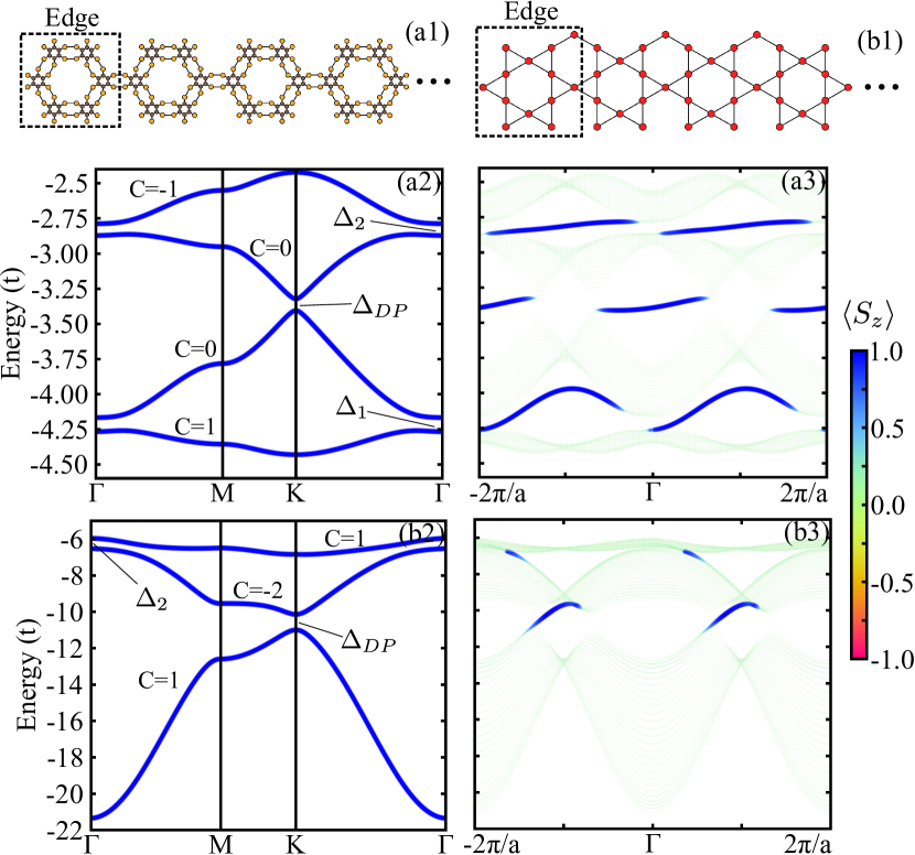
In order to provide further support and a more clear physical picture of the QAHE in the MOFs, we calculate the Chern number of (MC4S, and examined the formation of topologically protected metallic edge states in (MC4S nanoribbons. The calculations were performed within the TB model by considering one orbital per site. Here, based on the projected energy bands [Fig. 3], we have considered (i) four Hexagonal Multi-Orbital (HMO) bands, composed by the carbon and sulfur (C-S) lattice [Fig. 4(a1)], for the (MnC4S and (FeC4S MOFs; and (ii) Ru kagome lattice model [Fig. 4(b1)] for (RuC4S. The TB Hamiltonian can be written as Tang et al. (2011); de Lima et al. (2017),
| (3) |
where describe the on site energy and nearest and next-nearest neighbor hopping,
| (4) |
is the intrinsic spin-orbit coupling of the sites,
| (5) |
and is a Zeeman exchange field,
| (6) |
Here and , with and are the creation and annihilation operators of an electron in the -th site with spin ; stands for the Pauli matrices in the spin space. The are the vectors connecting the -th to the -th site, , , and controls the on-site, hopping, spin-orbit and Zeeman field strength, respectively. The hopping and spin-orbit terms depend on the distance between the sites, respectively
We have taken the normalization with respect to the first neighbor distance , , and ; and control of the range of the hopping, namely, for larger values () only first neighbor hopping has been considered, while for , , further neighbors are taken into account. In Figs. 4(a2)–(b2), we present the the energy bands for the C-S lattice, i.e. (FeC4S and (MnC4S [(i)], and the Ru kagome lattice [(ii)], where we find that the main features of the DFT bands have been nicely captured by the current TB approach tb- .
Based on the same TB approach, the topological character of the energy gaps was evaluated through the calculation of the Chern number (). By using the C-S model, as depicted in Fig. 4(a2), we found for the Fermi level lying in the energy gap , keeping the same values for the energy gaps and . Meanwhile, based on the Ru kagome lattice model, the Chern number is positive () at , and becomes negative () in , Fig. 4(b2). It is worth noting that the latter is a local gap at the point, since the energy bands become metallic due to the downward dispersion of the nearly flat kagome band. Since the anomalous Hall conductance is given by , it is predicted just one conducting channel per edge for a given energy position of the Fermi level, where opposite edges present conducting channels with opposite carrier velocities ().
Indeed, this is what we found along the edge sites of (MC4S of the NRs. We have considered NR structures with a width of 30 unit cells (, nm); and based on the C-S lattice model, in Fig. 4(a3) we present the calculated electronic band structure projected on the edge sites of the NR [dashed-square region in the Fig. 4(a1)]. We find only one conducting channel, i.e. only one topologically protected edge state associated with each non-trivial energy gap. All of them are characterized by the same direction for the carriers velocities, for instance in Fig. 2, and positive values of . Whereas, the opposite edge of the NR will present carrier velocities in the opposite direction (). Similarly, we find the emergence of topologically protected edge states in (RuC4S NRs described by the Ru kagome lattice model, Fig. 4(b1). As depicted in Fig. 4(b3), those edge states present one single conducting channel with positive values of spin-polarization, and carrier velocities one along the direction, and another one (characterized by a low density of states) with carrier velocities in the opposite direction, . Here, the former is associated with the non-trivial energy gap with , while the latter is due to the local non-trivial energy gap with .
III.5 MOF/G Charge transfer and the control the Fermi level
The manifestation of the QAHE, i.e. the appearance of (topologically) protected edge currents, relies on the energy position of the Fermi level with respect to the non-trivial energy gaps. In the present MOFs, as indicated in Fig. 3, we may place the Fermi level in the energy gap through electron doping processes. Indeed, this is what we obtained by charging the MOF by about /cm2, which is a quite feasible -type doping. It is worth noting that the net magnetization of the MOFs increases by about the same amount 0.2 , while the MAEs of the charged (MnC4S and (FeC4S MOFs are practically the same when compared with those of the neutral MOFs; whereas in (RuC4S, meV/Ru-atom. The required doping to achieve the QAH state in the (RuC4S makes the magnetic properties of the system more robust with respect to thermal perturbations. Such a -type doping can be done through the physisorption of the MOF on metal surfaces with work function smaller compared with that of the MOF; or we may consider an interface engineering based on 2D vdW heterostructures like MOF/graphene.
Graphene is a quite interesting substrate, since it provides both structural stability, and the -type doping of the MOFs discussed above. The work functions () of the MOFs (see Table 1) are about 1 eV larger compared with the that of graphene. Here we will focus on a particular MOF/graphene interface, (RuC4S/G mis .
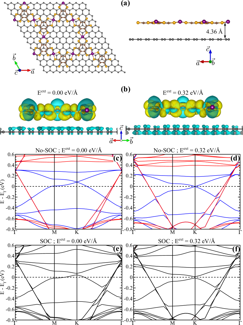
First, by considering a set of (RuC4S/G staking geometries, we find that the energetically most stable configuration is characterized by Ru atoms aligned on top of C atoms of the graphene sheet, as seen in Fig. 5(a). The energetic stability of (RuC4S/G was inferred by the calculation of the binding energy meV/Å2, which is defined as the total energy difference between the final system [(RuC4S/G] and the sum of the total energies of the isolated components, (RuC4S and single layer graphene. It is worth noting that this binding is larger than the one obtained for a graphene bilayer system, 2.2 meV/Å2. At the equilibrium geometry we find an interlayer distance of Å, Fig. 5(a), with no chemical bonds at the (RuC4S/G interface.
The larger work function of (RuC4S ( eV), compared with the one of graphene, will promote a net charge transfer from graphene to the MOF. In Fig. 5(b) we present a map of such a charge transfer, where the blue (yellow) regions illustrate the loss (gain) of electrons in each layer. Focusing on the electronic properties, based on the first-principles calculations, upon the formation of the (RuC4S/G interface, we find an up-shift of the Fermi level of (RuC4S, characterizing the -type doping of the MOF, whereas the graphene sheet becomes -type doped, with the Fermi level lying at 0.3 eV below the Dirac point. By turning on the SOC, Fig.5(e), the non-trivial energy gap of the MOF is the same compared with the one of isolated system; however, we find that the Fermi level of the (RuC4S/G system does not lie within , and thus, there is no appearance of anomalous Hall current along the edge sites.
In a previous studyde Lima et al. (2017), we verified that the occupation of the kagome bands, as well as the localization of the non-trivial energy gaps in MOF/MOF interfaces, can be controlled by an external electric field. It is worth to pointing out that the energy bands responsible to the QAH phase are completely spin polarized and separated, with the magnetization out of the MOF plane. In such a situation, the Rashba SOC does not affect the gap opened by the intrinsic SOC, thus contrasting with its non-magnetic QSH counterpartde Lima et al. (2017). Here, mediated by the MOFG charge transfers, the energy bands of the MOF and G system can be tuned by an EEF⟂ (perpendicular to the MOF/G interface). In particular, by increasing the -type doping of (RuC4S by an EEF⟂ of 0.32 eV/Å, we find the Fermi level lying on the DP of the MOF [Fig. 5(d)]; while the SOC gives rise to of 27 meV at the Fermi level, Fig. 5(f), promoting the (topologically) protected edge currents in (RuC4S/G, switchable on-and-off through an EEF⟂.
IV Summary and Conclusion
Based on combined first-principles DFT calculations and the tight-binding models, we have studied the electronic and the topological properties of (MC4S MOFs, with M = Mn, Fe, Co, Ru, and Rh. Our results of magnetic anisotropy energy (MAE) reveal that the (MC4S systems (with M = Mn, Fe and Ru) present the easy axis out-of-plane, while the other metals (Co and Rh) are characterized by an energetic preference for in-plane magnetization. Since both inversion and out-of-plane mirror reflection symmetries are preserved, the QAH phase is not expected in the latter group Ren et al. (2016). Meanwhile, the QAHE of the former MOF group was verified through the calculation of the (non-zero) Chern number, and the formation of the topologically protected edge states in MOF nanoribbons. Among the currently studied systems, (RuC4S presents the largest energy gap induced by the SOC. Upon -type doping (/cm2), in order to place the Fermi level in the non-trivial energy gap, we find that the MAE of (RuC4S increases by about 40%, thus improving its magnetic stability with respect to thermal perturbations. Such a tuning of the Fermi level, and the strengthening the out-of-plane magnetization in (RuC4S have been examined by considering the MOF adsorbed on the graphene sheet. The formation of the (RuC4S/G interface is an exothermic process, which may promote the structural stability of the MOF. Further tuning of the Fermi level has been done through an external electric field, EEF⟂, which control the G (RuC4S net charge transfer, and the appearance of topologically protected (spin-polarized) edge currents in the MOF. Here, although we have considered a single system, (RuC4S/G, we may infer that other MOF/G interfaces can be engineered to exploit/control the QAH properties, like magnetic anisotropy energy and the energy position of the Fermi level.
V ACKNOWLEDGMENTS
The authors acknowledge financial support from the Brazilian agencies CNPq, and FAPEMIG, and the CENAPAD-SP and Laboratório Nacional de Computação Científica (LNCC-SCAFMat) for computer time.
References
- Kane and Mele (2005) C. L. Kane and E. J. Mele, Phys. Rev. Lett. 95, 226801 (2005).
- Xu et al. (2013) Y. Xu, B. Yan, H.-J. Zhang, J. Wang, G. Xu, P. Tang, W. Duan, and S.-C. Zhang, Phys. Rev. Lett. 111, 136804 (2013).
- Drummond et al. (2012) N. D. Drummond, V. Zólyomi, and V. I. Fal’ko, Phys. Rev. B 85, 075423 (2012).
- Padilha et al. (2016) J. E. Padilha, R. B. Pontes, T. M. Schmidt, R. H. Miwa, and A. Fazzio, Scientific Reports 6, 26123 (2016).
- Qian et al. (2014) X. Qian, J. Liu, L. Fu, and J. Li, Science 346, 1344 (2014).
- Wang et al. (2013a) Z. F. Wang, Z. Liu, and F. Liu, Phys. Rev. Lett. 110, 196801 (2013a).
- Wang et al. (2013b) Z. F. Wang, N. Su, and F. Liu, Nano Letters 13, 2842 (2013b), pMID: 23678979.
- Kambe et al. (2013) T. Kambe, R. Sakamoto, K. Hoshiko, K. Takada, M. Miyachi, J.-H. Ryu, S. Sasaki, J. Kim, K. Nakazato, M. Takata, and H. Nishihara, Journal of the American Chemical Society 135, 2462 (2013).
- Zhao et al. (2013) M. Zhao, A. Wang, and X. Zhang, Nanoscale 5, 10404 (2013).
- Wang et al. (2017) A. Wang, X. Zhang, Y. Feng, and M. Zhao, The Journal of Physical Chemistry Letters 8, 3770 (2017), pMID: 28762733.
- Maeda et al. (2016) H. Maeda, R. Sakamoto, and H. Nishihara, Langmuir 32, 2527 (2016), pMID: 26915925.
- Alves et al. (2004) H. Alves, D. Simão, I. Cordeiro Santos, V. Gama, R. Teives Henriques, H. Novais, and M. Almeida, European Journal of Inorganic Chemistry 2004, 1318 (2004).
- Colson and Dichtel (2013) J. W. Colson and W. R. Dichtel, Nature Chemistry 5, 453 (2013), review Article.
- Sheberla et al. (2014) D. Sheberla, L. Sun, M. A. Blood-Forsythe, S. Er, C. R. Wade, C. K. Brozek, A. Aspuru-Guzik, and M. Dincă, Journal of the American Chemical Society 136, 8859 (2014), pMID: 24750124.
- Rodriguez-San-Miguel et al. (2016) D. Rodriguez-San-Miguel, P. Amo-Ochoa, and F. Zamora, Chem. Commun. 52, 4113 (2016).
- Sakamoto et al. (2016) R. Sakamoto, K. Takada, X. Sun, T. Pal, T. Tsukamoto, E. J. H. Phua, A. Rapakousiou, K. Hoshiko, and H. Nishihara, Coordination Chemistry Reviews 320-321, 118 (2016), sI: Functional Nanomaterials 2016.
- de Lima et al. (2017) F. C. de Lima, G. J. Ferreira, and R. H. Miwa, Phys. Rev. B 96, 115426 (2017).
- Hu et al. (2015) J. Hu, Z. Zhu, and R. Wu, Nano Letters 15, 2074 (2015), pMID: 25689149.
- Dong et al. (2016) L. Dong, Y. Kim, D. Er, A. M. Rappe, and V. B. Shenoy, Phys. Rev. Lett. 116, 096601 (2016).
- Zhang et al. (2012) H. Zhang, C. Lazo, S. Blügel, S. Heinze, and Y. Mokrousov, Phys. Rev. Lett. 108, 056802 (2012).
- Kim et al. (2016) H.-J. Kim, C. Li, J. Feng, J.-H. Cho, and Z. Zhang, Phys. Rev. B 93, 041404 (2016).
- Ren et al. (2016) Y. Ren, J. Zeng, X. Deng, F. Yang, H. Pan, and Z. Qiao, Phys. Rev. B 94, 085411 (2016).
- Kresse and Furthmüller (1996) G. Kresse and J. Furthmüller, Computational Materials Science 6, 15 (1996).
- Perdew et al. (1996) J. P. Perdew, K. Burke, and M. Ernzerhof, Phys. Rev. Lett. 77, 3865 (1996).
- Monkhorst and Pack (1976) H. J. Monkhorst and J. D. Pack, Phys. Rev. B 13, 5188 (1976).
- Blöchl (1994) P. E. Blöchl, Phys. Rev. B 50, 17953 (1994).
- Dudarev et al. (1998) S. L. Dudarev, G. A. Botton, S. Y. Savrasov, C. J. Humphreys, and A. P. Sutton, Phys. Rev. B 57, 1505 (1998).
- Lee et al. (2010) K. Lee, E. D. Murray, L. Kong, B. I. Lundqvist, and D. C. Langreth, Phys. Rev. B 82, 081101 (2010).
- Qiao et al. (2010) Z. Qiao, S. A. Yang, W. Feng, W.-K. Tse, J. Ding, Y. Yao, J. Wang, and Q. Niu, Phys. Rev. B 82, 161414 (2010).
- Acosta et al. (2014) C. M. Acosta, M. P. Lima, R. H. Miwa, A. J. R. da Silva, and A. Fazzio, Phys. Rev. B 89, 155438 (2014).
- Wang et al. (1993) D.-s. Wang, R. Wu, and A. J. Freeman, Phys. Rev. B 47, 14932 (1993).
- Song et al. (2017) Y. Song, X. Wang, and W. Mi, Phys. Rev. Materials 1, 074408 (2017).
- Tang et al. (2011) E. Tang, J.-W. Mei, and X.-G. Wen, Phys. Rev. Lett. 106, 236802 (2011).
- (34) For the (C–S) hexagonal multi-orbital [(i)] we have considered the following parameterization, Å, , , , and Å-1; and for the Ru kagome lattice [(ii)] we have used, , , and Å-1.
- (35) In order to satisfy the periodic boundary conditions, within our supecell approach, the graphene sheet was described by using a supercell with periodicity of (66), giving rise to lattice mismatch of 2.9%.
Appendix A GGA+U
In Table 2 we summarize our results of magnetic anisotropy energy () of (MC4S for M=Mn, Fe, Co, Ru, and Rh. Qualitatively, our results do not depend on the value of , which is only required for the quantitative description of the metal orbitals.
| 2 eV | 3 eV | 4 eV | ||||
|---|---|---|---|---|---|---|
| MOF | MAE | MAE | MAE | |||
| (MnC4S | 0.63 | 3.06 | 0.62 | 3.12 | 0.61 | 3.18 |
| (FeC4S | 0.28 | 2.90 | 0.31 | 2.15 | 0.39 | 2.22 |
| (CoC4S | -1.61 | 1.11 | -1.84 | 1.17 | -2.08 | 1.23 |
| (RuC4S | 2.14 | 1.78 | 1.98 | 1.86 | 1.84 | 1.92 |
| (RhC4S | -1.29 | 0.79 | -2.07 | 0.86 | -3.00 | 0.90 |