Fast real-time time-dependent
density functional theory calculations
with the parallel transport gauge
Abstract
Real-time time-dependent density functional theory (RT-TDDFT) is known to be hindered by the very small time step (attosecond or smaller) needed in the numerical simulation due to the fast oscillation of electron wavefunctions, which significantly limits its range of applicability for the study of ultrafast dynamics. In this paper, we demonstrate that such oscillation can be considerably reduced by optimizing the gauge choice using the parallel transport formalism. RT-TDDFT calculations can thus be significantly accelerated using a combination of the parallel transport gauge and implicit integrators, and the resulting scheme can be used to accelerate any electronic structure software that uses a Schrödinger representation. Using absorption spectrum, ultrashort laser pulse, and Ehrenfest dynamics calculations for example, we show that the new method can utilize a time step that is on the order of attoseconds in a planewave basis set, and is no less than times faster when compared to the standard explicit 4th order Runge-Kutta time integrator.
1 Introduction
Recent developments of ultrafast laser techniques have enabled a large number of excited state phenomena to be observed in real time. One of the most widely used techniques for studying ultrafast properties is the real-time time-dependent density functional theory (RT-TDDFT) 1, 2, which has achieved successes in a number of fields including e.g. nonlinear optical response 3 and the collision of an ion with a substrate 4. Nonetheless, the range of applicability of RT-TDDFT is often hindered by the very small time step needed to propagate the Schrödinger equation. Many numerical propagators used in practice are explicit time integrators 5, 6, 7, which require a small time step size satisfying due to the stability restriction. For discretized under a flexible basis set such as planewaves, the required time step is often less than attosecond (as). On the other hand, ultrafast properties often need to be observed on the order of femtoseconds (fs). This requires time steps to be performed and is often prohibitively expensive. Given the recent emphasis on ultrafast physics, this is thus an urgent problem to be solved.
However, physical observables such as the electron density are squared quantities of the wavefunctions, and often oscillate much slower. In this paper, we find that such gap is largely due to the non-optimal gauge choice of the Schrödinger dynamics, which is irrelevant to the computation of physical observables. We propose that the optimal gauge choice is given by a parallel transport formulation. Compared to the Schrödinger representation, the orbitals with the parallel transport gauge can often be “flattened” into an approximate straight line over a much longer time interval. When combined with implicit time integrators to propagate the parallel transport dynamics, it is possible to significantly increase the time step size without sacrificing accuracy. The parallel transport formulation only introduces one extra term to the Schrödinger equation, and thus can be easily applied to any electronic structure software packages for RT-TDDFT calculations, which is unlike to other methods where approximations and significant rewriting are needed 8, 9.
2 Theory
In order to derive the parallel transport gauge, let us first consider the RT-TDDFT equations
| (1) |
Here are the electron orbitals, and the Hamiltonian can depend explicitly on and nonlinearly on the density matrix or the electron density . Eq. (1) can be equivalently written using a set of transformed orbitals , where the gauge matrix is a unitary matrix of size . An important property of the density matrix is that it is gauge-invariant: , and always satisfies the von Neumann equation (or quantum Liouville equation)
| (2) |
Our goal is to optimize the gauge matrix, so that the transformed orbitals vary as slowly as possible, without altering the density matrix. This results in the following variational problem
| (3) |
Here measures the Frobenius norm of the time derivative of the transformed orbitals. The minimizer of (3), in terms of , satisfies 111See Appendix A for its derivation, also for an explanation on the name “parallel transport”
| (4) |
Eq. (4) implicitly defines a gauge choice for each , and this gauge is called the parallel transport gauge. The governing equation of each transformed orbital can be concisely written down as 222See Appendix A for its derivation, also for an explanation on the name “parallel transport”
| (5) |
or more concisely in the matrix form
| (6) |
The right hand side of Eq. (6) is analogous to the residual vectors of an eigenvalue problem in the time-independent setup. Hence follows the dynamics driven by residual vectors and is expected to vary slower than .
The advantage of the parallel transport gauge is most clear in the near adiabatic regime, when the right hand side of (6) approximately vanishes. Fig. 1 (a) demonstrates a simple example with one electron, and a time dependent Hamiltonian in one dimension. The initial state is the ground state of . Here the time-dependent potential is chosen to be , which is a double well potential with one fixed center at and one moving center . Fig. 1 (a) shows that while oscillates rapidly, the oscillation of the parallel transport orbital is significantly slower, and can thus be approximated by a straight line over a much larger interval. We remark that efficient numerical methods based on the construction of instantaneous adiabatic states have also been recently developed for the near adiabatic regime 8, 9. The advantage of the parallel transport dynamics is that it only operates on orbitals as in the original Schrödinger dynamics. Even outside the near adiabatic regime, Eq. (6) always yields the slowest possible dynamics due to the variational principle in Eq. (3).
In order to propagate the parallel transport dynamics numerically, all the RT-TDDFT propagation methods can be used since Eq. (6) only differs from Eq. (1) in one extra term . As an example, the parallel transport Crank-Nicolson scheme (PT-CN) gives rise to the following scheme
| (7) |
Here is the Hamiltonian at the time step , and . Other time integrators can be straightforwardly generalized to the parallel transport dynamics as well (see Appendix B). In Eq. (2), the solution needs to be solved self-consistently. This is a set of nonlinear equations with respect to the unknowns , and can be efficiently solved by e.g. the preconditioned Anderson mixing scheme 10. The propagation of can also be naturally combined with the motion of nuclei discretized e.g. by the Verlet scheme for the simulation of Ehrenfest dynamics 11.
| Method | Error | |
|---|---|---|
| S-RK4 | 0.01 | |
| PT-RK4 | 0.01 | |
| S-RK4 | 0.005 | |
| PT-RK4 | 0.005 |
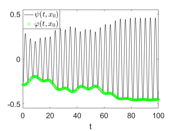
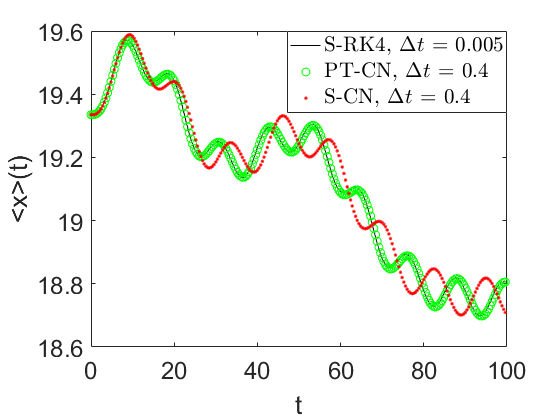
Since the parallel transport dynamics yields the optimal gauge choice, it can be used to improve the accuracy and efficiency of any propagator currently applied to the Schrödinger dynamics. For example, let us first consider again the one dimensional Schrödinger equation. Table 1 compares the explicit 4th order Runge-Kutta scheme for the Schrödinger dynamics (S-RK4) and the parallel transport dynamics (PT-RK4), which indicates that the error of the latter is considerably smaller. When combined with implicit integrators, we can further significantly increase the time step size. We compare the PT-CN scheme with the standard CN scheme for the Schrödinger dynamics (S-CN), and use S-RK4 with a small time step as the benchmark. The accuracy is measured by the dipole moment along the trajectory. Fig. 1 (b) indicates that PT-CN can use a much larger time step than S-RK4 without losing accuracy. On the other hand, while S-CN can still be numerically stable with the same step size, it becomes significantly less accurate after the first peak around .
3 Numerical results
We demonstrate the performance of the PT-CN scheme for RT-TDDFT calculations for three real systems representing three prototypical usages of RT-TDDFT. Our method is implemented in PWDFT code, which uses the planewave basis set and is a self-contained module in the massively parallel DGDFT (Discontinuous Galerkin Density Functional Theory) software package 12, 13. We use the Perdew-Burke-Ernzerhof (PBE) exchange correlation functional 14, and the Optimized Norm-Conserving Vanderbilt (ONCV) pseudopotentials 15, 16.
The first example is the computation of the absorption spectrum of an anthracene molecule. We set the time step size of PT-CN to be attoseconds (as), and that of S-RK4 to be 1 as (it becomes unstable when the step size is larger). Fig. 2 compares the absorption spectrum obtained from PT-CN and S-RK4 with PWDFT. This result is benchmarked against the linear response time-dependent density functional theory (LR-TDDFT) calculation using the turboTDDFT module 17 from the Quantum ESPRESSO software package 18, which performs Lanczos steps along each perturbation direction to evaluate the polarization tensor. A Lorentzian smearing of eV is applied to all calculations. We find that the absorption spectrum calculations from the three methods agree very well. The spectrum obtained from PT-CN and that from S-RK4 are nearly indistinguishable below eV, and becomes slightly different above eV. Note that the -pulse simultaneously excites all eigenstates from the entire spectrum, and eV already amounts to the time scale of as, which is approaching the step size of the PT-CN method. Since the computational cost of RT-TDDFT calculations is mainly dominated by the cost of applying the Hamiltonian operator to orbitals, we measure the numerical efficiency using the number of such matrix-vector multiplications per orbital. The PT-CN method requires on average matrix-vector multiplications for each orbital. This is comparable to the S-RK4 method which requires matrix-vector multiplications per time step. Hence for this example, the PT-CN method is around times faster than the S-RK4 method.

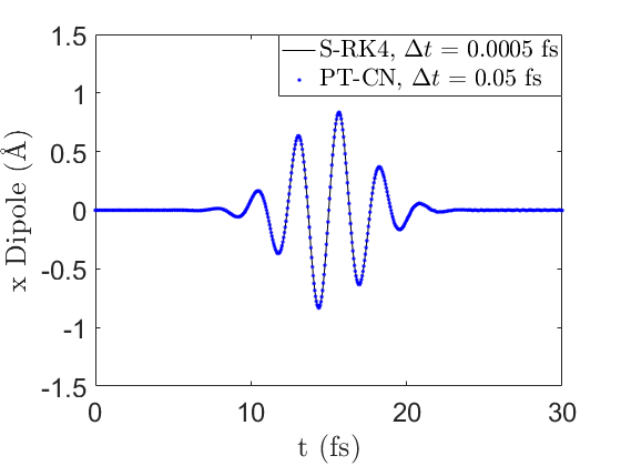
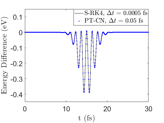
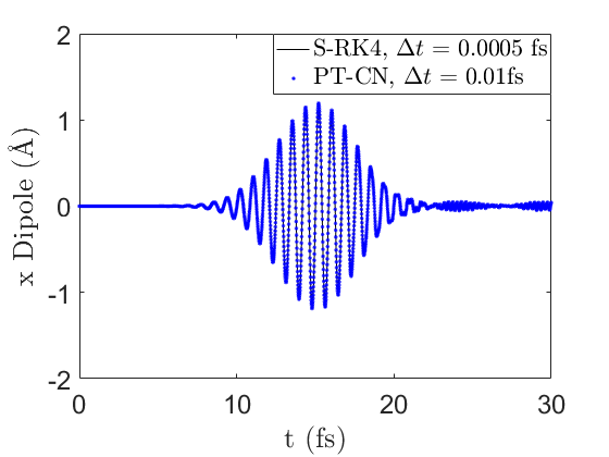
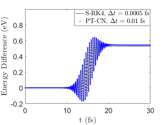
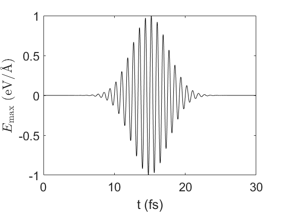
The second system is a benzene molecule driven by an ultrashort laser pulse. We apply two lasers with its wavelength being 800 nm and 250 nm, respectively. We measure the accuracy using the dipole moment along the x direction, as well as the energy difference along the trajectory, as shown in Fig. 3. For the case of the 800 nm laser, Fig. 3 confirms that the results of PT-CN with a time step size of as fully match those obtained from the S-RK4 method with a time step that is 100 times smaller. Again S-RK4 becomes unstable when the time step size is larger than as. After 25.0 fs, the increase of the total energy for S-RK4 and PT-CN is eV and eV, respectively, indicating negligible energy absorption due to the band gap of the system. During the time interval for which the laser is active (from 5.5 fs to 24.5 fs), the average number of matrix-vector multiplications per orbital in each PT-CN time step is 12.6, and the total number of matrix-vector multiplications per orbital is 4798. The total number of matrix-vector multiplications per orbital for S-RK4 within the same time interval is 152000, and the speedup of PT-CN over RK4 is .
The 250 nm laser has a higher photon energy above the benzene band gap, and thus results in significant energy absorption. In this case, even physical observables such as dipole moments become fast oscillating, and PT-CN needs to adopt a smaller step size as and still yields very good approximation to the electron dynamics compared to S-RK4. The increase of the total energy after 25.0 fs for S-RK4 and PT-CN is eV and eV, respectively. The average number of matrix-vector multiplications per orbital in each PT-CN time step is 8.3 due to the reduced step size, and the total number of matrix-vector multiplications per orbital is 15817. Therefore in this case PT-CN achieves 9.6 times speedup over S-RK4.
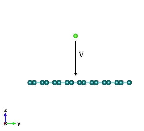
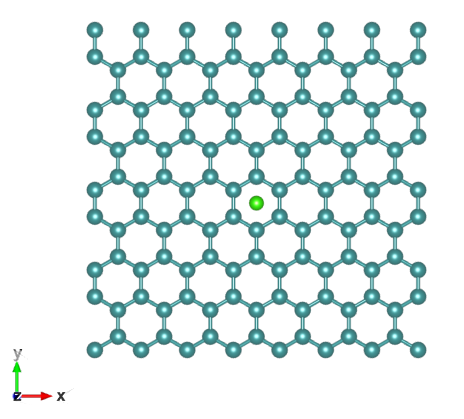
As the last example, we use the RT-TDDFT based Ehrenfest dynamics to study the process of a chlorine ion (Cl-) colliding to a graphene nanoflake consisting of 112 atoms. This models the ion implantation procedure for doping a substrate. At the beginning of the simulation, the Cl- is placed at 6 Å away from the graphene and is given an initial velocity perpendicular to the plane of the graphene pointing towards the center of one hexagonal ring formed by the carbon atoms. The initial velocity of Cl- is set to be , , , , , and Bohr/fs, and the kinetic energy carried by the ion ranges from eV to eV, respectively. The simulation is terminated before the ion reaches the boundary of the supercell. For instance, we set fs when the velocity is Bohr/fs. In such case, the time step size for PT-CN and S-RK4 is set to be as and as, respectively. Each PT-CN step requires on average matrix-vector multiplication operations per orbital, and the overall speedup of PT-CN over S-RK4 is .
We compare the result obtained from the Ehrenfest dynamics with that from the Born-Openheimer Molecular Dynamics (BOMD). In the BOMD simulation, since the extra electron of Cl- will localize on the conduction band of the graphene conduction rather than on Cl during the self-consistent field iteration, we replace the Cl- ion by the Cl atom. Fig. 4 (a) illustrates the energy transfer with different initial kinetic energies. As the Cl/Cl- initial kinetic energy increases, the gain of the kinetic energy by the graphene atoms decreases due to that Cl/Cl- can pass through the system faster. When the initial kinetic energy of Cl/Cl- is smaller than 500 eV, the losses of the kinetic energy for Cl/Cl- are similar between RT-TDDFT and BOMD. However, when the initial kinetic energy of Cl/Cl- further increases, the RT-TDDFT predicts an increase of the loss of the Cl/Cl- kinetic energy, while the gain of the graphene kinetic energy remains decreasing. This is a consequence of the electron excitation, which is absent in the BOMD simulation. Such excitation is illustrated in Fig. 4 (b) for the occupied electron density of states in the higher energy regimes. The occupied density of states is calculated as . Here is the -th orbital obtained at the end of the RT-TDDFT simulation at time , and are the eigenvalues and wavefunctions corresponding to the Hamiltonian at time . is a Dirac- function with a Gaussian broadening of eV.


Fig. 5 presents further details of the energy transfer along the trajectory of the RT-TDDFT and BOMD simulation when the initial velocity is 2.0 Bohr/fs (2057 eV). When the collision occurs at around fs, the loss of the Cl/Cl- kinetic energy is 44 eV and 58 eV under RT-TDDFT and BOMD, respectively. However, after collision Cl regains almost all the kinetic energy in BOMD, and the final kinetic energy is only 2.5 eV less than the initial one. Correspondingly, the kinetic energy of the graphene increases by eV and the potential energy increases by 1.63 eV. On the other hand, RT-TDDFT predicts that the Cl- ion should lose eV kinetic energy, which is mostly transferred to the potential energy of the excited electrons. The increase of the kinetic energy of the graphene is eV and is similar to the BOMD result. Therefore, in RT-TDDFT, the Cl- loses its kinetic energy to electron excitation in graphene.

4 Conclusion
In this work, we demonstrate that one significant factor leading to the very small time step size in RT-TDDFT calculations is the non-optimal gauge choice in the Schrödinger dynamics. Since all physical observables should be gauge-independent, we may optimize the gauge choice to improve the numerical efficiency without sacrificing accuracy. The resulting scheme can be beneficial to any RT-TDDFT integrator, and can even be nearly symplectic. With the increased time step size, we hope that RT-TDDFT can be used to study many ultrafast problems unamenable today.
Acknowledgement
This work was partially supported by the National Science Foundation under Grant No. 1450372, No. DMS-1652330 (D. A., W. J. and L. L.), and by the Department of Energy under Grant No. DE-SC0017867, No. DE-AC02-05CH11231 (L. L.), and by the Department of Energy Theory of Materials (KC2301) program under Contract No. DE-AC02-05CH11231 (L. W.). We thank the National Energy Research Scientific Computing (NERSC) center and the Berkeley Research Computing (BRC) program at the University of California, Berkeley for making computational resources available. We thank Stefano Baroni, Roberto Car, Zhanghui Chen, Wei Hu, Christian Lubich and Chao Yang for helpful discussions.
Appendix A Appendix A: Derivation of the parallel transport gauge
In order to solve (3), we first split into two orthogonal components
| (8) |
Then we have
| (9) |
To reformulate the second term, we take the time derivative on the equation and get
| (10) |
Thus Eq. (9) becomes
| (11) |
where the last equality comes from that and is a unitary gauge matrix.
Eq. (11) has a clear physical interpretation. The second term
| (12) |
is defined solely from the density matrix and is thus gauge-invariant. Therefore the variation of is minimized when
| (13) |
which is exactly the parallel transport condition.
Now we would like to directly write down the governing equation of . First, the equation and the parallel transport condition (4) imply that
| (14) |
Together with the von Neumann equation, we have
| (15) |
This is exactly the parallel transport dynamics.
The name “parallel transport gauge” originates from the parallel transport formulation associated with a family of density matrices , which generates a parallel transport evolution operator as (see e.g. 19, 20)
| (16) |
We demonstrate that starting from an initial set of orbitals , the solution to the parallel transport dynamics (6) is simply evolved by the parallel transport evolution operator according to . To show this, we first prove the following relation
| (17) |
by showing that both sides solve the same initial value problem. Note that satisfies
| (18) |
We then would like to derive the differential equation satisfies. Taking the time derivative on both sides of the identity , we have
| (19) |
and thus
| (20) |
Then
On the other hand,
Therefore
| (21) |
Together with the same initial value , we have proved . Using this relation, we have
| (22) |
Since is unitary, we have for all . Hence forms an orthogonal basis in the image of . Therefore
| (23) |
By Eq. (17), (21) and the von Neumann equation, we have
| (24) |
Finally using Eq. (22) and (23), we have
thus precisely solves the parallel transport dynamics, indicating .
Appendix B Appendix B: Time discretization schemes
We list several propagation schemes used in this paper, but the parallel transport dynamics can be discretized with any propagator. Here all the is the Hamiltonian at step , and , . For implicit time integrators, or needs to be solved self-consistently.
The standard explicit 4th order Runge-Kutta scheme for the Schrödinger dynamics (S-RK4):
| (25) |
The standard explicit 4th order Runge-Kutta scheme for the parallel transport dynamics (PT-RK4):
| (26) |
The implicit Crank-Nicolson scheme for the Schrödinger dynamics (S-CN):
| (27) |
The implicit Crank-Nicolson scheme for the parallel transport dynamics (PT-CN):
| (28) |
Appendix C Appendix C: Details of RT-TDDFT calculations
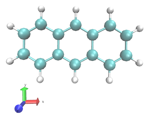
For the example of absorption spectrum of anthracene (C14H10, Fig. 6). The simulation is performed using a cubic supercell of size , and the kinetic energy cutoff is au. In order to compute the absorption spectrum, a -pulse of strength au is applied to the directions to the ground state wavefunctions respectively, and the system is then propagated for fs along each direction. This gives the polarization tensor , and the optical absorption cross-section is evaluated as
For the example of the benzene molecule driven by an ultrashort laser pulse, the electric field takes the form
| (29) |
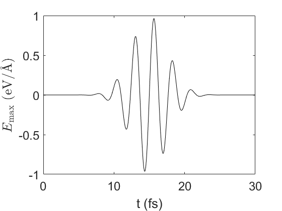
where is a unit vector defining the polarization of the electric field. The parameters define the width, the initial position of the center, the maximum amplitude of the Gaussian envelope, and the frequency of the laser, respectively. In practice and are often determined by the wavelength and the full width at half maximum (FWHM) pulse width 21, i.e. and , where is the speed of the light. In this example, the peak electric field is 1.0 eV/Å, occurring at fs. The FWHM pulse width is 6.0 fs, and the polarization of the laser field is aligned along the axis (the benzene molecule is in - plane). We consider one relatively slow laser with wavelength 800 nm, and another faster laser with wavelength 250 nm, respectively (Fig. 7). The electron dynamics for the first laser is in the near adiabatic regime, where the system stays near the ground state after the active time interval of the laser, while the second laser drives a significant amount of electrons to excited states. We propagate RT-TDDFT to fs. For the parameters in the Anderson mixing, the step length is , the mixing dimension is 10, and the tolerance is .
Even though the electron dynamics varies rapidly under the laser with 250 nm wavelength, PT-CN can still be stable within a relatively large range of time steps. Table 2 measures the accuracy of PT-CN with 5 as, 6.5 as, 7.5 as, 10 as and 20 as, respectively. We find that the number of matrix-vector multiplications per orbital systematically reduces as the step size increases. When 20 as, the speed up over S-RK4 is , and this is at the expense of overestimating the energy by eV after the active interval of the laser. Hence one may adjust the time step size to obtain a good compromise between efficiency and accuracy, and use PT-CN to quickly study the electron dynamics with a large time step. This is not possible using an explicit scheme like S-RK4.
| Method | (fs) | AEI (eV) | AOE (eV) | MVM | Speedup |
|---|---|---|---|---|---|
| S-RK4 | 0.0005 | 0.5260 | / | 152000 | / |
| PT-CN | 0.005 | 0.5340 | 0.0080 | 28610 | 5.3 |
| PT-CN | 0.0065 | 0.5347 | 0.0087 | 22649 | 6.7 |
| PT-CN | 0.0075 | 0.5362 | 0.0102 | 21943 | 6.9 |
| PT-CN | 0.01 | 0.5435 | 0.0175 | 15817 | 9.6 |
| PT-CN | 0.02 | 0.5932 | 0.0672 | 12110 | 12.6 |
For the ion collision example, the system is shown in Fig. 8. The supercell has 113 atoms (including Cl-) sampled at the point. The length of the box along the direction is 12 Å and the Cl- ion is placed 6 Å away from the graphene nanoflake. The initial velocity is perpendicular to the center of one hexagonal ring of the graphene nanoflake. The kinetic energy cutoff is 30 Hartree. The system has 228 states and each state is occupied with 2 electrons, and the calculation is performed with 228 computational cores at NERSC. The initial velocity of Cl- ion is set to be Bohr/fs. We stop the simulation after Cl- passes through the graphene sheet, so the total simulation time is fs, respectively. The time step size for PT-CN method is set to be as in the simulation accordingly.
We find that PT-CN method is again more efficient compared to the S-RK4 method. For example, in the case of Bohr/fs test, the time step for PT-CN can be chosen to be as, while the time step for the S-RK4 method cannot be chosen to be larger than as. PT-CN needs 27 matrix-vector multiplications per orbital for each RT-TDDFT step, and S-RK4 needs 4. So PT-CN is around times faster than S-RK4 for this test.
References
- Runge and Gross 1984 Runge, E.; Gross, E. K. U. Density-functional theory for time-dependent systems. Phys. Rev. Lett. 1984, 52, 997
- Onida et al. 2002 Onida, G.; Reining, L.; Rubio, A. Electronic excitations: density-functional versus many-body Green’s-function approaches. Rev. Mod. Phys. 2002, 74, 601
- Takimoto et al. 2007 Takimoto, Y.; Vila, F. D.; Rehr, J. J. Real-time time-dependent density functional theory approach for frequency-dependent nonlinear optical response in photonic molecules. J. Chem. Phys. 2007, 127, 154114
- Krasheninnikov et al. 2007 Krasheninnikov, A. V.; Miyamoto, Y.; Tománek, D. Role of electronic excitations in ion collisions with carbon nanostructures. Phys. Rev. Lett. 2007, 99, 016104
- Castro et al. 2004 Castro, A.; Marques, M.; Rubio, A. Propagators for the time-dependent Kohn-Sham equations. J. Chem. Phys. 2004, 121, 3425–33
- Schleife et al. 2012 Schleife, A.; Draeger, E. W.; Kanai, Y.; Correa, A. A. Plane-wave pseudopotential implementation of explicit integrators for time-dependent Kohn-Sham equations in large-scale simulations. J. Chem. Phys. 2012, 137, 22A546
- Gómez Pueyo et al. 2018 Gómez Pueyo, A.; Marques, M. A.; Rubio, A.; Castro, A. Propagators for the time-dependent Kohn-Sham equations: multistep, Runge-Kutta, exponential Runge-Kutta, and commutator free Magnus methods. J. Chem. Theory. Comput. 2018,
- Jahnke and Lubich 2003 Jahnke, T.; Lubich, C. Numerical integrators for quantum dynamics close to the adiabatic limit. Numer. Math. 2003, 94, 289–314
- Wang et al. 2015 Wang, Z.; Li, S.-S.; Wang, L.-W. Efficient Real-Time Time-Dependent Density Functional Theory Method and its Application to a Collision of an Ion with a 2D Material. Phys. Rev. Lett. 2015, 114, 1–5
- Anderson 1965 Anderson, D. G. Iterative procedures for nonlinear integral equations. J. Assoc. Comput. Mach. 1965, 12, 547–560
- Lubich 2008 Lubich, C. From quantum to classical molecular dynamics: reduced models and numerical analysis; European Mathematical Society, 2008
- Lin et al. 2012 Lin, L.; Lu, J.; Ying, L.; E, W. Adaptive local basis set for Kohn-Sham density functional theory in a discontinuous Galerkin framework I: Total energy calculation. J. Comput. Phys. 2012, 231, 2140–2154
- Hu et al. 2015 Hu, W.; Lin, L.; Yang, C. DGDFT: A massively parallel method for large scale density functional theory calculations. J. Chem. Phys. 2015, 143, 124110
- Perdew et al. 1996 Perdew, J. P.; Burke, K.; Ernzerhof, M. Generalized gradient approximation made simple. Phys. Rev. Lett. 1996, 77, 3865–3868
- Hamann 2013 Hamann, D. R. Optimized norm-conserving Vanderbilt pseudopotentials. Phys. Rev. B 2013, 88, 085117
- Schlipf and Gygi 2015 Schlipf, M.; Gygi, F. Optimization algorithm for the generation of ONCV pseudopotentials. Comput. Phys. Commun. 2015, 196, 36–44
- Malcıoğlu et al. 2011 Malcıoğlu, O. B.; Gebauer, R.; Rocca, D.; Baroni, S. turboTDDFT–A code for the simulation of molecular spectra using the Liouville–Lanczos approach to time-dependent density-functional perturbation theory. Comput. Phys. Commun. 2011, 182, 1744–1754
- Giannozzi et al. 2009 Giannozzi, P.; Baroni, S.; Bonini, N.; Calandra, M.; Car, R.; Cavazzoni, C.; Ceresoli, D.; Chiarotti, G. L.; Cococcioni, M.; Dabo, I.; Corso, A. D.; de Gironcoli, S.; Fabris, S.; Fratesi, G.; Gebauer, R.; Gerstmann, U.; Gougoussis, C.; Kokalj, A.; Lazzeri, M.; Martin-Samos, L.; Marzari, N.; Mauri, F.; Mazzarello, R.; Paolini, S.; Pasquarello, A.; Paulatto, L.; Sbraccia, C.; Scandolo, S.; Sclauzero, G.; Seitsonen, A. P.; Smogunov, A.; Umari, P.; Wentzcovitch, R. M. QUANTUM ESPRESSO: a modular and open-source software project for quantum simulations of materials. J. Phys.: Condens. Matter 2009, 21, 395502–395520
- Nakahara 2003 Nakahara, M. Geometry, topology and physics; CRC Press, 2003
- Cornean et al. 2017 Cornean, H. D.; Monaco, D.; Teufel, S. Wannier functions and Z2 invariants in time-reversal symmetric topological insulators. Rev. Math. Phys. 2017, 29, 1730001
- Russakoff et al. 2016 Russakoff, A.; Li, Y.; He, S.; Varga, K. Accuracy and computational efficiency of real-time subspace propagation schemes for the time-dependent density functional theory. J. Chem. Phys. 2016, 144, 204125