Observation of gyromagnetic reversal
Abstract
We report direct observation of gyromagnetic reversal, which is the sign change of gyromagnetic ratio in a ferrimagnet Ho3Fe5O12, by using the Barnett effect measurement technique at low temperatures. The Barnett effect is a phenomenon in which magnetization is induced by mechanical rotation through the coupling between rotation and total angular momentum of electrons. The magnetization of Ho3Fe5O12 induced by mechanical rotation disappears at 135 K and 240 K. The temperatures correspond to the magnetization compensation temperature and the angular momentum compensation temperature , respectively. Between and , the magnetization flips over to be parallel against the angular momentum due to the sign change of gyromagnetic ratio. This study provides an unprecedented technique to explore the gyromagnetic properties.
Gyromagnetic ratio—the ratio of magnetic moment to angular momentum is an essential concept in magnetism. An electron has negative gyromagnetic ratio, and its magnetic moment is antiparallel to the spin angular momentum. In fact, most of magnets have a negative gyromagnetic ratio since their magnetization is caused by electrons. In contrast, some magnets with multiple magnetic ions have a temperature dependent total gyromagnetic ratio, and even exhibit sign change: gyromagnetic reversal, which has manifested itself in some measurementsXin2006 ; Binder2006 ; Kim2017 . Here, we report direct observation of gyromagnetic reversal in a ferrimagnetic insulator Ho3Fe5O12 (HoIG). We show that the net internal angular momentum of HoIG clearly disappears around 240 K, and, below the temperature, it flips over to be parallel to the magnetization. This technique allowed us to investigate gyromagnetic properties, which is essential to accelerate spintronics and magnetic devices.
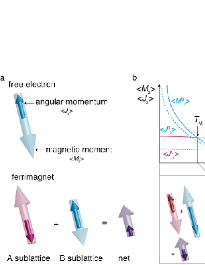
In 1915, S. J. Barnett reported that matter is magnetized when it is rotated, and this effect has since been called the Barnett effectBarnett1915 . His experiment demonstrated that the magnetization of a material carries internal angular momentum owing to electron spinsBarnett1915 ; Barnett1935 . On an electron, the angular momentum and the magnetic moment are antiparallel (Fig.1 a), namely, the gyromagnetic ratio is negative. Most magnets have thus internal angular momentum antiparallel to their magnetization. When a magnet is rotated, the internal angular momentum is modulated via spin-rotation coupling, and then its magnetization is modified based on its gyromagnetic ratio. This is the mechanism of the Barnett effect. Therefore, the magnetization induced by the Barnett effect reflects the gyromagnetic ratio including its sign.
The gyromagnetic ratio shows various temperature dependence in some ferrimagnets. In ferrimagnets, magnetic moments in magnetic sublattices align antiparallel to each other(Fig.1 a). In the case that the magnetization of two sublattices have different temperature dependence (Fig.1 b) owing to differences in the intra-sublattice exchange interactions, these magnetizations can cancel each other at a certain temperature called the magnetization compensation temperature , at which the magnet has zero net magnetization. In addition, the internal angular momentums can cancel each other at a different temperature called the angular momentum compensation temperature in the case that magnetic ions on different sublattice have different factor (Fig.1 b).
Interestingly, across or , the net magnetization reverses with respect to the angular momentum (Fig.1 b): gyromagnetic reversal. Between the two temperatures, the magnetization and the angular momentum are parallel. The existence of and has often been discussed in terms of anomalies in various magnetic properties around the temperaturesOstler2012 ; Wangsness1953 ; Wangsness1954 ; Xin2006 ; Stanciu2006 ; Stanciu2007 ; Vahaplar2009 ; Radu2011 ; Kobayashi2005 ; Kim2017 .
In this letter, we demonstrated the gyromagnetic reversal using the apparatus possessing the capability to measure the Barnett effect at low temperatures. We found that the magnetization of HoIG is reversed at two temperatures. One coincides with determined by the conventional magnetization measurement, and the other corresponds to . In addition, the effective gyromagnetic ratio is positive in the region between and , which is regarded as an additional state in terms of the gyromagnetic effect.
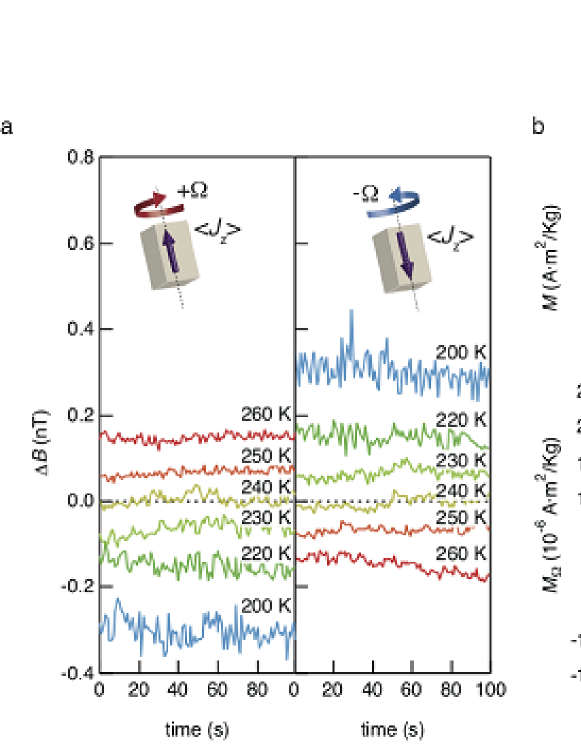
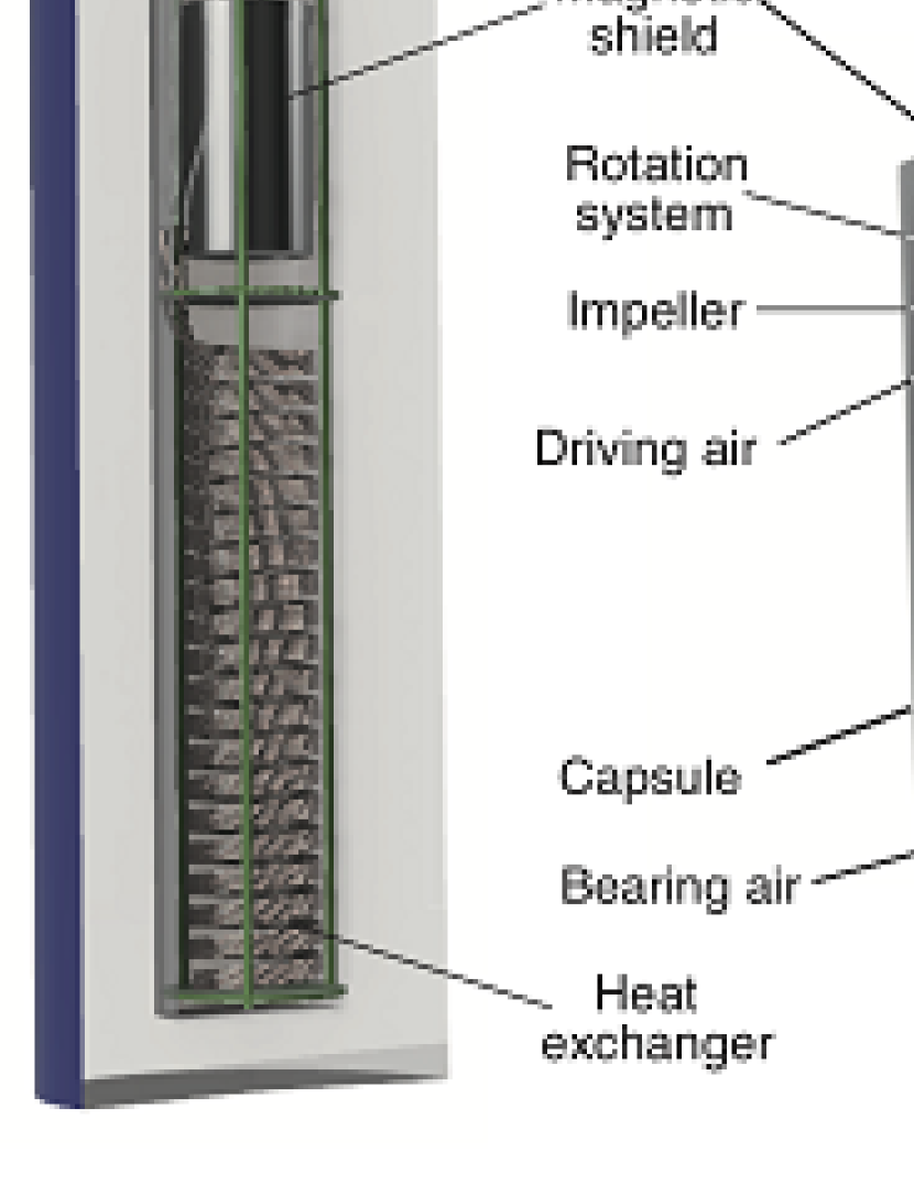
Figure 2a shows a schematic illustration of our experimental setup. We used an air-driven rotor systemOno2015 ; Ogata2017A ; Ogata2017B and extended it to low-temperature measurement. The rotation system was inserted into a cryostat, and the rotor was driven by nitrogen gas cooled through a heat exchanger. The magnetization induced by the Barnett effect was estimated by measuring the stray field from the rotated sample, as shown in Fig.2b. The value of was detected by using a fluxgate magnetic sensor placed near the sample. The details of the apparatus are explained in the section.2. As a sample, we used HoIG, which has two magnetic ions of Ho3+ and Fe3+ (see the section.1), because ferrimagnetic HoIG ( K) shows the magnetic compensation at KPauthenet1958 ; Geller1965 , which is within the available temperature of our apparatus.
The time evolution of and the rotational speed is shown in Fig. 2c, indicates that the sample is magnetized along the direction of rotation because increases and decreases in sync with the switching of the direction of rotation. By repeating the switching process, we averaged to be accurate. The value of is stable during rotation and depends linearly on the rotational frequency, as shown in Fig.2d. These results indicate that our custom-built measures the Barnett effect correctly.
Figure 3a shows the temperature dependence of the variation of the stray field by mechanical rotation at kHz. The decreases with decreasing temperature and disappears at 240 K. Although the magnetization induced by magnetic field persists at 240 K, which is much higher than the magnetic compensation temperature ( K) as shown in the upper panel of Fig.3b, the magnetization in rotation is zero. The result indicates that the net angular momentum disappears at 240 K: the angular momentum compensation point. Below 240 K, surprisingly, the sign of reverses, and the magnitude of the field increases toward 200 K. This means that the direction of the magnetic moment with respect to the angular momentum turns toward the opposite direction below 240 K, that is, gyromagnetic reversal occurs.
The magnetization induced by the rotation () can be estimated from by using a dipole field modelOno2015 ; Ogata2017A ; Ogata2017B . The lower panel of Fig.3b shows the temperature dependence of . At 135 K, becomes zero. Although the net angular momentum is non-zero at , there is no response to the rotation because the spontaneous magnetization disappears. At 135 K, the sign of reverses, and below 135 K, the net magnetic moment and the net angular momentum become antiparallel again. Thus, the gyromagnetic reversal state is realized at temperatures between =135 K and =240 K.
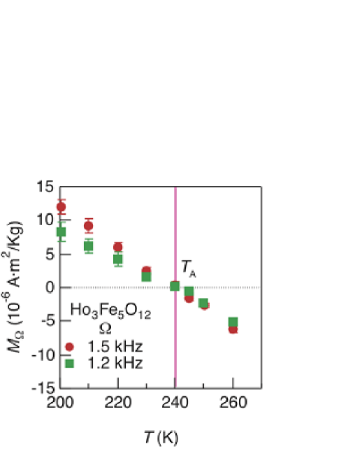
The angular momentum compensation temperature obtained at the rotation frequency of 1.2 kHz is equivalent to that at 1.5 kHz, as shown in Fig.4a, indicating that does not depend on the rotation frequency. This result is consistent with the fact that the net angular momentum is zero at . The Barnett effect disappears and is zero because spin-rotation coupling is zero regardless .
The temperature controllable Barnett effect measurement makes it possible to determine and of bulk ferrimagnets. These compensation points have attracted attention from the viewpoint of developing next-generation magnetic devices, such as spin valve induced by the spin torqueXin2006 and high-speed switching deviceStanciu2007 ; Vahaplar2009 ; Radu2011 . In addition, recently, domain wall mobility was found to be enhanced at in the measurement of field-driven domain wall motion on the ferrimagnetic metal GdFeCoKim2017 . The technique proposed here open new opportunities in the search for suitable ferrimagnets for device, because the measurement can be performed on all bulk samples whether metal or insulator, without micro fabrication technique. Not limited to ferrimagnets, the technique will be essential for gyromagnetic properties such as the contribution of orbital angular momentum in 3–5, 4–5 electron compounds.
.1 Sample preparation.
A powder sample of Ho3Fe5O12 was prepared by means of a solid-state reaction. Fe2O3(4N) and Ho2O3(3N) were mixed in a molar ratio of 5:3 in an agate mortar. The mixture was pelletized and heated up to .
.2 Experimental setup of Barnett experiment at low temperature.
An air-driven rotor (produced by JEOL) was used and customized to rotate the samples in the forward and backward directions at frequencies up to 1.5 kHz. To perform measurements below room temperature, air flow was replaced with cooled nitrogen gas flow. A long copper tube wound into a coil was inserted into the cryostat as a heat exchanger, and it was cooled by liquid nitrogen sprayed into the cryostat. The compressed nitrogen gas was cooled in the heat exchanger, and then the gas temperature was controlled by using the heater. Thereafter, the nitrogen gas was blown on to the rotor enclosing the sample. The gas temperature was monitored by the thermometer adjacent to the rotor and the value was fed back to the output of the heater.
The pelletized sample of Ho3Fe5O12 was crushed in powder, and then the powder was packed in a spindle capsule with a diameter of 6 mm and length of 16 mm. The stray field from the sample was measured with a fluxgate magnetic sensor (Fluxmaster, Stefan Mayer Instruments, Dinslaken, Germany) placed near the rotor, as shown in Fig.2b. The measurement was performed with positive and negative rotation as one set, and it was repeated 10 times or more to remove background noise. The stray field was obtained from . The magnetization induced by the Barnett effect was evaluated using the following dipole model: , where , , and are the sensor–sample distance, sample length, and sample mass, respectively. This measurement system was placed inside a double magnetic shield to suppress fluctuations of the environmental magnetic field, for example, due to geomagnetism.
Acknowledgements.
This work was financially supported by ERATO, JST, a Grant-in-Aid for Scientific Research on Innovative Areas Nano Spin Conversion Science (26103005) from MEXT, Japan, a Grant-in-Aid for Scientific Research A (26247063) from MEXT, Japan, a Grant-in-Aid for Scientific Research B (16H04023) from MEXT, Japan, a Grant-in-Aid for Scientific Research C (15K05153, 16K06805) from MEXT, Japan, and a Grant-in-Aid for Young Scientists B (16K18353) from MEXT, Japan.References
- (1) X. Jiang, L. Gao, J. Z. Sun, and S. S. P. Parkin, Phys. Rev. Lett. 97, 217202 (Nov 2006), https://link.aps.org/doi/10.1103/PhysRevLett.97.217202
- (2) M. Binder, A. Weber, O. Mosendz, G. Woltersdorf, M. Izquierdo, I. Neudecker, J. R. Dahn, T. D. Hatchard, J.-U. Thiele, C. H. Back, and M. R. Scheinfein, Phys. Rev. B 74, 134404 (Oct 2006), https://link.aps.org/doi/10.1103/PhysRevB.74.134404
- (3) K.-J. Kim, S. K. Kim, Y. Hirata, S.-H. Oh, T. Tono, D.-H. Kim, T. Okuno, W. S. Ham, S. Kim, G. Go, et al., Nature materials 16, 1187 (2017), https://www.nature.com/articles/nmat4990
- (4) S. J. Barnett, Phys. Rev. 6, 239 (Oct 1915), https://link.aps.org/doi/10.1103/PhysRev.6.239
- (5) S. J. Barnett, Rev. Mod. Phys. 7, 129 (Apr 1935), https://link.aps.org/doi/10.1103/RevModPhys.7.129
- (6) T. Ostler, J. Barker, R. Evans, R. Chantrell, U. Atxitia, O. Chubykalo-Fesenko, S. El Moussaoui, L. Le Guyader, E. Mengotti, L. Heyderman, et al., Nature communications 3, 666 (2012), https://www.nature.com/articles/ncomms1666
- (7) R. K. Wangsness, Phys. Rev. 91, 1085 (Sep 1953), https://link.aps.org/doi/10.1103/PhysRev.91.1085
- (8) R. K. Wangsness, Phys. Rev. 93, 68 (Jan 1954), https://link.aps.org/doi/10.1103/PhysRev.93.68
- (9) C. D. Stanciu, A. V. Kimel, F. Hansteen, A. Tsukamoto, A. Itoh, A. Kirilyuk, and T. Rasing, Phys. Rev. B 73, 220402 (Jun 2006), https://link.aps.org/doi/10.1103/PhysRevB.73.220402
- (10) C. D. Stanciu, A. Tsukamoto, A. V. Kimel, F. Hansteen, A. Kirilyuk, A. Itoh, and T. Rasing, Phys. Rev. Lett. 99, 217204 (Nov 2007), https://link.aps.org/doi/10.1103/PhysRevLett.99.217204
- (11) K. Vahaplar, A. M. Kalashnikova, A. V. Kimel, D. Hinzke, U. Nowak, R. Chantrell, A. Tsukamoto, A. Itoh, A. Kirilyuk, and T. Rasing, Phys. Rev. Lett. 103, 117201 (Sep 2009), https://link.aps.org/doi/10.1103/PhysRevLett.103.117201
- (12) I. Radu, K. Vahaplar, C. Stamm, T. Kachel, N. Pontius, H. Dürr, T. Ostler, J. Barker, R. Evans, R. Chantrell, et al., Nature 472, 205 (2011), https://www.nature.com/articles/nature09901
- (13) T. Kobayashi, H. Hayashi, Y. Fujiwara, and S. Shiomi, IEEE transactions on magnetics 41, 2848 (2005), http://ieeexplore.ieee.org/document/1519138
- (14) M. Ono, H. Chudo, K. Harii, S. Okayasu, M. Matsuo, J. Ieda, R. Takahashi, S. Maekawa, and E. Saitoh, Phys. Rev. B 92, 174424 (Nov 2015), https://link.aps.org/doi/10.1103/PhysRevB.92.174424
- (15) Y. Ogata, H. Chudo, M. Ono, K. Harii, M. Matsuo, S. Maekawa, and E. Saitoh, Applied Physics Letters 110, 072409 (2017), https://doi.org/10.1063/1.4976998
- (16) Y. Ogata, H. Chudo, B. Gu, N. Kobayashi, M. Ono, K. Harii, M. Matsuo, E. Saitoh, and S. Maekawa, Journal of Magnetism and Magnetic Materials 442, 329 (2017), https://doi.org/10.1016/j.jmmm.2017.06.101
- (17) R. Pauthenet, Ann. Phys.(Paris) 3, 424 (1958)
- (18) S. Geller, J. P. Remeika, R. C. Sherwood, H. J. Williams, and G. P. Espinosa, Phys. Rev. 137, A1034 (Feb 1965), https://link.aps.org/doi/10.1103/PhysRev.137.A1034