Deployment of the Saddle Space Transformation in Tracking the Base of Support
Carlo Tiseo1,2,*, Ming Jeat Foo1,2, Kalyana C Veluvolu 3, Wei Tech Ang1,2,
1 Rehabilitation Research Institute of Singapore, 50 Nanyang Avenue N3-01a-01,Singapore 639798, Singapore;
2 School of Mechanical & Aerospace Engineering, Nanyang Technological University, 50 Nanyang Avenue N3-01a-01,Singapore 639798, Singapore;
3 School of Electronics Engineering,Kyungpook National University, Daegu 702701, South Korea;
* carlotiseo@gmail.com
Abstract
Balance is the fundamental skill behind human locomotion, and its impairment is the principal indicator of self-perceived disability. Despite significant improvements in balance assessment, there is still large incidence of fall related injuries among elderlies. The Base of Support (BoS) is a popular method for bipedal stability assessment, but its accuracy depends on the accuracy the BoS geometry measurement. This work presents a method to ease the BoS tracking by the identification of a reference frame that allows to define postural models of the BoS geometry. Although we also propose a geometry based on the geometry determined from centre of pressure range of motion within the foot obtained from literature, this methodology can be used with other models (i.e., the feasible base of support). The model has been tested with 12 healthy subjects, which have been asked to explore their stability in six different postures. The results show that the model can accurate deform the geometry of the BoS to adapt its shape to the different postures, which can remove the necessity of force/torque sensors in some application. Potentially the proposed method can be also applied to describe any posture dependent attribute (e.g., gravitational forces), and it can be also applied to bipedal robots. Therefore, it constitutes a novel mathematical tool that can be deployed to develop both better sensors and models for bipeds. For example, it can be used with the Extrapolated CoM model to evaluate dynamic stability from the body kinematics.
Introduction
Human bipedal balance is a fundamental skill that is required for the execution of standing activities [9, 17]. Despite the challenging dynamics involved in the balance mechanism, humans are peculiarly effective in controlling their equilibrium in unstructured environments [19]. Furthermore, the human stability control is affected by the physiological ageing due to the increase of reaction times to perturbation [9, 13, 19]. This often leads to mobility impairments which significantly affects the independence and safety of the elderly population [19]. Despite the relevance to rapidly ageing societies, there has not been any substantial improvement of the rehabilitation therapies in the last decades [5, 3, 26, 12, 28].
The balance as defined by Pollock et al [17] involves three activities: the maintenance of the desired posture, the voluntary change between postures, and the reaction to external perturbations. Currently, the balance assessment is mainly based on the analysis Base of Support (BoS) and Centre of Gravity (or Centre of Mass, CoM),where posture and movements are defined stable as long as the CoM position is contained within the BoS [17, 27]. The accuracy of such approach depends an accurate tracking of both the BoS and CoM, which can be challenging in unstructured environments being both of them posture dependant quantities [27]. Nonetheless, this approach has been widely adopted in human studies due to its good accuracy and low computational cost, there is not standard method to track BoS geometry [8, 11, 15, 26, 7, 6, 4]. Usually, the BoS is identified as the smallest convex hull enclosing the contact the area of the feet with the ground, which includes the area between them during the double support phase [29].
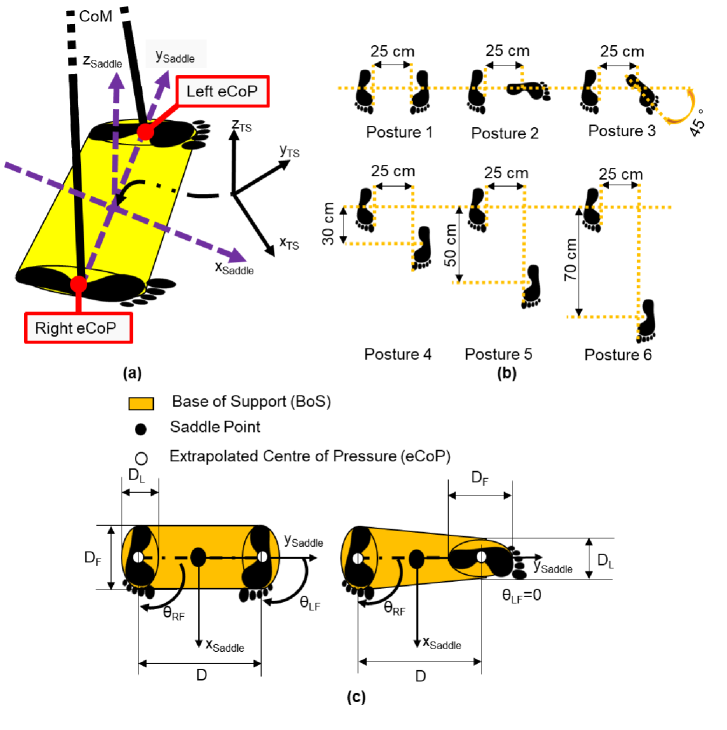
Recently, our group used the potential energy surface produced by the two legs to analyse human balance during walking. We defined a posture dependant space, called Saddle Space, to study the potential energy of the system during posture changes (Figure 1.(a)). The main advantage of this space is the possibility to define a single model for BoS geometry that can be projected in the task space [21, 20, 24, 23]. The Saddle Space model is based on the identification of a reference point within the foot (i.e., extrapolated Centre of Pressure or eCoP), and a Base of Support (BoS) that describes the range of motion of the physical the centre of pressure within the foot. The position of the eCoP and the shape BoS have been defined according to the data reported by Hof et al [8] as described in A. Furthermore, we have also conducted preliminary validation to test the hypothesis that the Saddle Space transformation can accurately track BoS geometry comparing the model output with experimental results reported in literature [21]. Lastly, we have also proved in [20] that tracking the BoS evolution during locomotion is a generalization of the extrapolated CoM model proposed by Hof et al [8]. In fact, the extrapolated CoM provides the inclination of for a step frequency equal to the natural frequency of the inverted pendulum, which describes the minimum step required to achieve stability at a selected velocity [20, 24, 23, 1].
This manuscript develops a posture dependent model to track the BoS based on the foot kinematics, which can now be deployed for the development of sensor to track balance assessment and supervision in daily living environments. To validate the accuracy of the proposed model, 12 subjects have been asked to explore their stability in the six different postures as represented in Figure 1.(b). The results show that the transformation of the Saddle Space is an efficient methodology for the analysis of the bipeds, even though the proposed CoM geometrical model does not fully model the region where healthy subjects can stabilize their body. This reduced accuracy was expected because the proposed model consider the CoM as a fixed within the human body while in reality CoM is posture dependent. Nonetheless, given the difficulty in tracking the human posture and inertias accurately, the geometrical model is usually considered a good approximation [16, 8, 27, 11].
The BoS model used in this paper and the experimental set-up are described in Section Materials and Methods. The results are presented in Section Results and discussed in Section Discussions, which also analyses the BoS model limitations and possible improvements by using the Capture Regions (CR) used for bipedal robots [18]. Section Conclusions draws the conclusions.
Materials and Methods
This Section starts with the presentation of the model employed for the BoS and, subsequently, it describes the experimental method for validation.
Base of Support Model
The human legs have an anisotropic shape implies that BoS shape depends not only on the feet position but also from their orientation in the space. The formulation of our model starts from the definition of the Saddle reference frame as shown in Figure 1.(a). The transformation from the Saddle reference frame (SS) to the Task-space (TS) coordinates is:
| (1) |
where and are the coordinates in the TS and the SS reference frames respectively. , , and are the coordinates of two eCoPs. Lastly, is the angle between the abscissa axis of the two reference frames.
The transformation in Equation 1 can be used to express the BoS boundaries defined in the SS (formulated in the following equation) in the TS, as exemplified in Figure 1.(c).
| (2) |
where is the angle between a given direction and ; instead, , , , and are defined as follows:
| (3) |
The geometry of the convex hull defined by each foot is defined based on the measure of the eCoP trajectory during standing as reported in [8]. The point defined as eCoP in this model represents the fulcrum of rotation of our inverted pendulum model that is placed at the centre of this area. Although usual inverted pendulum model uses the eCoP as fulcrum of rotation, the proposed approach is based on the growing evidence that human internal model accounts for a fixed reference within the foot [20, 2].
Validation Method
The validation of the proposed model involves the analysis of the pelvic movements range of 12 healthy subjects (7 males and 5 females) in 6 different postures (as shown Figure 1.(b)). The participants’ age, mass, and height are 28.33.4 years, 71.112.6 kg and 1.7110.7 m respectively. All the subjects provided written informed consent to the experiment.
The subjects were instructed to move their pelvis to explore the borders of the area they were comfortable to move in for about 30 seconds per posture while keeping their torso in an erect position parallel to the frontal plane. They were allowed to partially lift-up the feet as long as the orientations of the feet were kept constant.
Ten passive markers have been placed on the subjects as described in the A. Their movements have been recorded by an 8-cameras motion capture system from Vicon controlled with Nexus Software. Subsequently, the data have been imported to Matlab (Mathworks Inc) for the data analysis to validate if the SS can be used to track the BoS and, the accuracy of the proposed model based on the geometrical properties of the foot soles. This resulted in the following protocol:
-
1.
The covariances of the CoM trajectories were compared with the ideal BoS predicted by the proposed model for each posture, where the anthropometric parameters required by the model have been set to the mean of subjects’ anthropometry.
-
2.
The Points of Inclusion (POI) is defined as the percentage of recorded CoM positions that are within the boundaries predicted by the model.
(4) -
3.
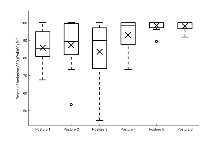
The Points of Inclusion 360 (PoI360) is the POI considering only the samples on the outer border in the saddle space of the recorded data for each subject. This allows to evaluate if the CoM range of motion is included in the BoS by considering farthest point reached by the CoM trajectories in every direction.
(5)
Results
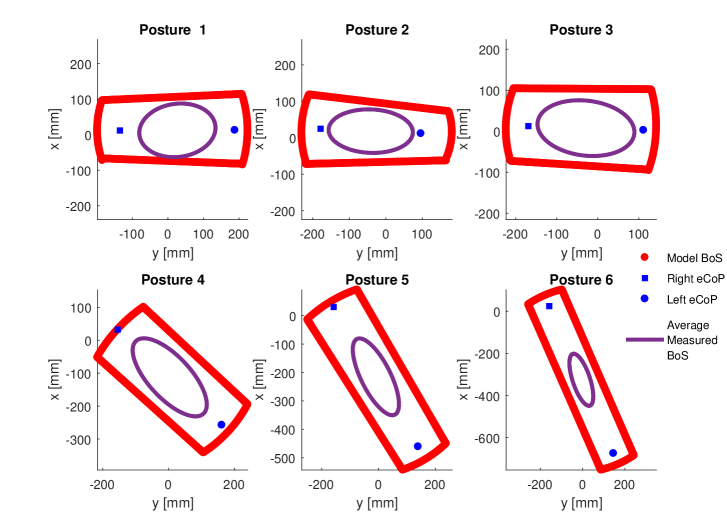
The analysis of the mean areas covered by the subjects in the 6 different postures is shown in Figure 2. The comparison of the measured data with the proposed model shows that Equation 1 is able to adequately project the shape of the BoS in the Saddle Space (Equation 2) in the different postures.
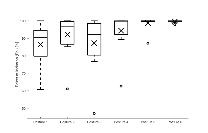
The values of the mean PoI for postures 1-6 are 86.511.6%, 92.211.3%, 87.2615.0%, 94.410.7%, 98.83.7% and 99.60.7% respectively. The data analysis shows that the subjects are able to go beyond the model predicted BoS when they adopt a posture which allows a better range of motion contributing to a lower mean PoI. On the contrary, their PoI increases when they assume postures that introduce higher postural constraints, as shown the Figure 3.
The results of the PoI are also confirmed by the PoI360, which has mean values of 85.810.6%, 87.313.8%, 83.518.0%, 93.010.27%, 98.33.2% and 98.03.2% for the six postures respectively. Furthermore, the mean PoI360 values increase with the postural constraints of the posture similarly to the PoI, which can be observed by comparing Figures 3 and 4.
Discussions
Experimental results validate the initial hypothesis that Equation 1 can accurately project geometries defined in the saddle space in the task space. Nevertheless, the current geometrical models of the BoS still retains most of the limitations of the previous formulations mentioned in Section LABEL:Sec:1. The proposed can be further improve accounting for the alteration of its geometry due to the changes of the inclination of the feet’ soles with respect to the ground.
The direct relationship of both PoIs to the increase in postural constraints highlights the limitation of the BoS geometrical models in the stability evaluation for highly redundant systems. The BoS concept accurately describes the stability of rigid bodies (i.e. seesaw, rigid inverted pendulum), where the Centre of Mass (CoM) is fixed within the geometry, and the gravitational forces are counteracted by the structure rigidity [17]. On the other hand, the CoM confinement within the BoS is a necessary but not a sufficient condition for stability in non-rigid structures, where such analysis has also to account for the forces required to retain the desired configuration.
The CoM location is not constant in reconfigurable structures, and its calculation requires the complete knowledge of the kinematics and dynamics of the systems. Therefore, the CoM tracking becomes extremely complex for high-dimensional structures such as human body. A common way to deal with such problem is to sacrifice some accuracy by using a fixed location of a landmark-based CoM defined considering anatomical landmarks and ergonomics, as the one used in this paper [8, 11, 15, 7, 6, 26, 4, 27].
The stability conditions analysed in the previous two paragraphs only considers the static stability, which resides in the ability to retain a posture. However, there is also a dynamic stability condition, which requires not only the ability to counteract the external forces acting on the systems but also the management its own kinetic energy. There are different ways to account for the system energetics, but the most commonly used impose kinematics constraints based on the inverted pendulum analogy[8, 10, 27], and they require input of the ground reaction forces that are not easily collected in unstructured environments. On the other hand, the proposed model provides an alternative framework for the implementation of available methods to evaluate stability. For example, the eXtrapolated-CoM (XCoM) can be implemented with IMUs and optoelectronic system (i.e. motion capture) using the proposed method to derive the required parameters (BoS, CoM position and Velocity) from the body kinematics.
Furthermore, equation 1 allows the transformation of physical quantities from a posture dependent SS to the TS. Therefore, it opens with a new framework to describe posture dependent parameters used both for humans and robots. For example, as the proposed model allows to project the BoS to the TS accurately, it can be used to model capture region generated by the two legs, which describes the area of space where a bipedal robot can attract the CoM towards a fixed point under specific dynamic conditions [18].
Conclusions
The experimental results demonstrate that the model presented in this paper can be instrumental in the characterisation of bipedal systems in general. Furthermore, our results show that it has a good level of accuracy, despite the drawbacks caused by having the model relying on geometrical definition for the BoS and the CoM.
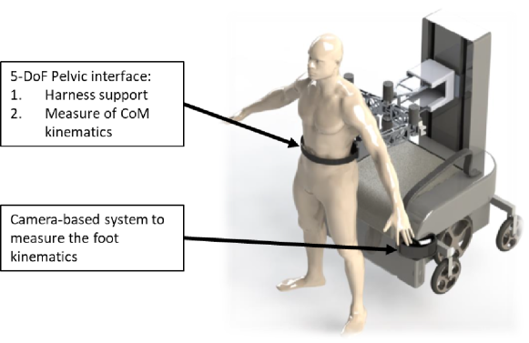
Nonetheless, at the current stage, these models can be only employed for rehabilitation robots when harness support is provided due to safety constraints. Therefore, it satisfies the requirement for our application where the robot should provide harness support without interfering with the patients’ locomotor strategies through a sensorized pelvic interface [25, 22]. Furthermore, we are currently implementing this method in a camera-based sensor system to measure the feet postures that will be mounted on the robotic base, while the position of the CoM will be measured via the pelvic interface kinematics, as shown in Figure 5.
Lastly, the proposed Saddle Space has been proven to be a convenient way to describe, observe and measure bipedal systems stability and it can be used regardless of the geometry defined for the BoS of the two feet. Thus, the development of a dynamic model in such space may ease and improve the control, planning and performance assessment of bipedal locomotion in the future.
Acknowledgements
This research was supported by the A*STAR-NHG-NTU Rehabilitation Research Grant: ”Mobile Robotic Assistive Balance Trainer” (RRG/16018). This experiment has been approved by the NTU Internal Review Board, Reference Number: IRB-2016-09-015. Figure 6.(a) has been reprinted from Journal of Biomechanics, 38, A.L. Hof M.G.J. Gazendam and W.E. Sinke, The condition for dynamic stability, 1-8, 2005 [8] with permission from Elsevier.
Conflicts of Interest
The authors declare no conflict of interest.
Abbreviations
The following abbreviations are used in this manuscript:
BoS
Base of Support
CoM
Centre of Mass
CoP
Centre of Pressure
eCoP
extrapolated Centre of Pressure
TS
Task Space
SS
Saddle Space
PoI
Points of Inclusion
PoI360
Points of Inclusion 360
Appendix A Marker Set and Model Reference Points Calculation
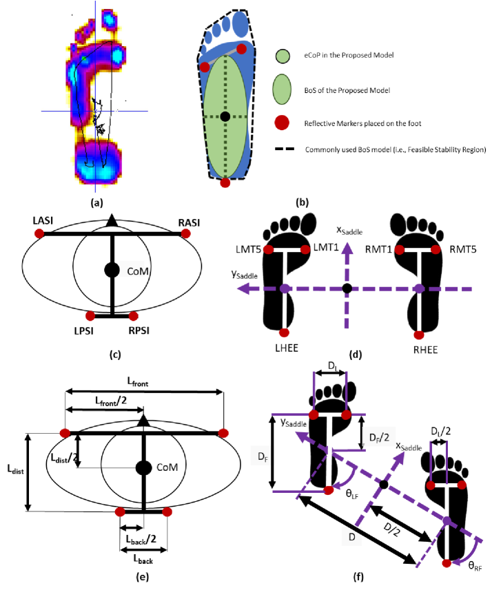
Ten IR reflective markers were placed on the subjects to capture the CoM position, feet positions and orientation. The proposed model uses the eCoP position and the base of support of the feet to derive the BoS from the feet’s posture. The eCoP and the feet’s BoS geometry have been defined based on the measure of the CoP range of motion (Figure 6.(a)) reported by Hof et al in [8] as shown in Figure 6.(b). Figures 6 and 6 also shows the positions of the markers placed on the pelvis and feet of the subjects, with the description given below that is a subset of the marker set used in [14]:
-
•
LASI: Directly above spina iliaca anterior superior (left)
-
•
RASI: Directly above spina iliaca anterior superior (right)
-
•
LPSI: Directly above spina iliaca posterior superior (left)
-
•
RPSI: Directly above spina iliaca posterior superior (right)
-
•
LHEE: Center of left heel
-
•
RHEE: Center of right heel
-
•
LMT1: Left first metatarsal bone
-
•
LMT5: Left fifth metatarsal bone
-
•
RMT1: Right first metatarsal bone
-
•
RMT5: Right fifth metatarsal bone
The CoM and both the eCoPs for the feet are calculated from the marker positions as shown in Figure 6. The foot width is the distance between the two markers on the metatarsals, whereas foot length is the distance between the marker on the heel and the midpoint of . The distance between the feet is the distance between the midpoints of the two . The foot orientation is the angle between and ( and ).
References
- 1. W. T. A. Carlo Tiseo, Kalyana C Veluvolu. Bioinspired straight walking task-space planner. arXiv preprint arXiv:1808.10799v1, 2018.
- 2. J. Carpentier, M. Benallegue, and J.-P. Laumond. On the centre of mass motion in human walking. International Journal of Automation and Computing, 2017.
- 3. I. Díaz, J. J. Gil, and E. Sánchez. Lower-Limb Robotic Rehabilitation: Literature Review and Challenges. Journal of Robotics, 2011(i):1–11, 2011.
- 4. J. M. Font-Llagunes and J. Kövecses. Dynamics and energetics of a class of bipedal walking systems. Mechanism and Machine Theory, 44(11):1999–2019, nov 2009.
- 5. A. C. H. Geurts, M. de Haart, I. J. W. van Nes, J. Duysens, M. D. Haart, I. J. W. V. Nes, J. Duysens, M. de Haart, I. J. W. van Nes, and J. Duysens. A review of standing balance recovery from stroke. Gait & posture, 22(3):267–81, nov 2005.
- 6. L. Hak, H. Houdijk, P. J. Beek, and J. H. van Dieën. Steps to Take to Enhance Gait Stability: The Effect of Stride Frequency, Stride Length, and Walking Speed on Local Dynamic Stability and Margins of Stability. PLoS ONE, 8(12):e82842, dec 2013.
- 7. L. Hak, J. H. van Dieën, P. van der Wurff, M. R. Prins, A. Mert, P. J. Beek, and H. Houdijk. Walking in an Unstable Environment: Strategies Used by Transtibial Amputees to Prevent Falling During Gait. Archives of Physical Medicine and Rehabilitation, 94(11):2186–2193, nov 2013.
- 8. A. Hof, M. Gazendam, and W. Sinke. The condition for dynamic stability. Journal of Biomechanics, 38(1):1–8, jan 2005.
- 9. F. E. Huxham, P. a. Goldie, and a. E. Patla. Theoretical considerations in balance assessment. The Australian journal of physiotherapy, 47(2):89–100, jan 2001.
- 10. A. D. Kuo. The six determinants of gait and the inverted pendulum analogy: A dynamic walking perspective. Human Movement Science, 26(4):617–656, aug 2007.
- 11. V. Lugade, V. Lin, and L.-s. Chou. Center of mass and base of support interaction during gait. Gait & Posture, 33(3):406–411, mar 2011.
- 12. S. Maggioni, A. Melendez-Calderon, E. van Asseldonk, V. Klamroth-Marganska, L. Lünenburger, R. Riener, and H. van der Kooij. Robot-aided assessment of lower extremity functions: a review. Journal of NeuroEngineering and Rehabilitation, 13(1):72, dec 2016.
- 13. B. E. Maki and W. E. McIlroy. Cognitive demands and cortical control of human balance-recovery reactions. Journal of Neural Transmission, 114(10):1279–1296, oct 2007.
- 14. C. Mandery, O. Terlemez, M. Do, N. Vahrenkamp, and T. Asfour. The KIT whole-body human motion database. In 2015 International Conference on Advanced Robotics (ICAR), volume 611909, pages 329–336. IEEE, jul 2015.
- 15. P. M. McAndrew Young and J. B. Dingwell. Voluntary changes in step width and step length during human walking affect dynamic margins of stability. Gait & Posture, 36(2):219–224, jun 2012.
- 16. Y. C. Pai and J. Patton. Center of mass velocity-position predictions for balance control. Journal of biomechanics, 30(4):347–54, apr 1997.
- 17. A. Pollock, B. Durward, P. Rowe, and J. Paul. What is balance? Clinical Rehabilitation, 14(4):402–406, aug 2000.
- 18. J. Pratt and R. Tedrake. Velocity-Based Stability Margins for Fast Bipedal Walking. In Fast Motions in Biomechanics and Robotics, pages 299–324. Springer Berlin Heidelberg, Berlin, Heidelberg, 2006.
- 19. A. L. Rosso, S. a. Studenski, W. G. Chen, H. J. Aizenstein, N. B. Alexander, D. a. Bennett, S. E. Black, R. Camicioli, M. C. Carlson, L. Ferrucci, J. M. Guralnik, J. M. Hausdorff, J. Kaye, L. J. Launer, L. a. Lipsitz, J. Verghese, and C. Rosano. Aging, the Central Nervous System, and Mobility. The Journals of Gerontology Series A: Biological Sciences and Medical Sciences, 68(11):1379–1386, nov 2013.
- 20. C. Tiseo. Modelling of bipedal locomotion for the development of a compliant pelvic interface between human and a balance assistant robot. PhD thesis, Nanyang Technological University, 2018.
- 21. C. Tiseo and W. T. Ang. The Balance: An energy management task. In 2016 6th IEEE International Conference on Biomedical Robotics and Biomechatronics (BioRob), pages 723–728. IEEE, jun 2016.
- 22. C. Tiseo, W. T. Ang, and C. Y. Shee. Dynamics of the mobile robotic balance trainer: Study of the pentagonal closed chain properties in relation with balance tasks. In 2015 IEEE International Conference on Rehabilitation Robotics (ICORR), pages 753–757. IEEE, aug 2015.
- 23. C. Tiseo, M. J. Foo, K. C. Veluvolu, and A. W. Tech. A Postural Model for Tracking the Base of Support. In 2018 40th Annual International Conference of the IEEE Engineering in Medicine and Biology Society, EMBC 2018, 2018.
- 24. C. Tiseo, K. C. Veluvolu, and W. T. Ang. Evidence of a “ Clock ” Determining Human Locomotion. In 2018 40th Annual International Conference of the IEEE Engineering in Medicine and Biology Society, EMBC 2018, 2018.
- 25. C. Tiseo, Zhen Yi Lim, Cheng Yap Shee, and Wei Tech Ang. Mobile Robotic Assistive Balance Trainer — An intelligent compliant and adaptive robotic balance assistant for daily living. In 2014 36th Annual International Conference of the IEEE Engineering in Medicine and Biology Society, volume 2014, pages 5300–5303. IEEE, aug 2014.
- 26. D. Torricelli, J. Gonzalez, M. Weckx, R. Jiménez-Fabián, B. Vanderborght, M. Sartori, S. Dosen, D. Farina, D. Lefeber, and J. L. Pons. Human-like compliant locomotion: state of the art of robotic implementations. Bioinspiration & Biomimetics, 11(5):051002, aug 2016.
- 27. F. B. van Meulen, D. Weenk, E. H. F. van Asseldonk, H. M. Schepers, P. H. Veltink, and J. H. Buurke. Analysis of Balance during Functional Walking in Stroke Survivors. PLOS ONE, 11(11):e0166789, nov 2016.
- 28. C. J. Winstein, J. Stein, R. Arena, B. Bates, L. R. Cherney, S. C. Cramer, F. Deruyter, J. J. Eng, B. Fisher, R. L. Harvey, C. E. Lang, M. MacKay-Lyons, K. J. Ottenbacher, S. Pugh, M. J. Reeves, L. G. Richards, W. Stiers, and R. D. Zorowitz. Guidelines for Adult Stroke Rehabilitation and Recovery. Stroke, 47(6):e98–e169, jun 2016.
- 29. F. Yang, D. Espy, and Y. C. Pai. Feasible stability region in the frontal plane during human gait. Annals of Biomedical Engineering, 37(12):2606–2614, 2009.