english \frefformatplainapp\Frefappname\fancyrefdefaultspacing#1 \Frefformatplainapp\Frefappname\fancyrefdefaultspacing#1 \frefformatvarioapp\frefappname\fancyrefdefaultspacing#1#3 \Frefformatvarioapp\Frefappname\fancyrefdefaultspacing#1#3 \pStartPage179
Area-Preserving Parameterizations for Spherical Ellipses
Abstract
We present new methods for uniformly sampling the solid angle subtended by a disk. To achieve this, we devise two novel area-preserving mappings from the unit square to a spherical ellipse (i.e. the projection of the disk onto the unit sphere). These mappings allow for low-variance stratified sampling of direct illumination from disk-shaped light sources. We discuss how to efficiently incorporate our methods into a production renderer and demonstrate the quality of our maps, showing significantly lower variance than previous work.
{CCSXML}<ccs2012> <concept> <concept_id>10010147.10010371.10010372</concept_id> <concept_desc>Computing methodologies Rendering</concept_desc> <concept_significance>500</concept_significance> </concept> <concept> <concept_id>10010147.10010371.10010372.10010374</concept_id> <concept_desc>Computing methodologies Ray tracing</concept_desc> <concept_significance>500</concept_significance> </concept> <concept> <concept_id>10010147.10010371.10010372.10010377</concept_id> <concept_desc>Computing methodologies Visibility</concept_desc> <concept_significance>300</concept_significance> </concept>
</ccs2012>
\ccsdesc[500]Computing methodologies Rendering \ccsdesc[500]Computing methodologies Ray tracing \ccsdesc[300]Computing methodologies Visibility
\printccsdesc1 Introduction
Illumination from area light sources is among the most important lighting effects in realistic rendering, due to the ubiquity of such sources in real-world scenes. Monte Carlo integration is the standard method for computing the illumination from such luminaires [SWZ96]. This method is general and robust, supports arbitrary reflectance models and geometry, and predictively converges to the actual solution as the number of samples increases. Accurately sampling the illumination from area light sources is crucial for minimizing the amount of noise in rendered images.
Estimating the direct illumination at a point requires sampling the radiance contribution from directions inside the solid angle subtended by the given luminaire. A sensible strategy is to distribute those directions uniformly. This, however, is hard to achieve for an arbitrary-shaped luminaire, as it involves first computing and then uniformly sampling its subtended solid angle. Specialized methods have been proposed for spherical [Wan92], triangular [Arv95, Ure00], rectangular [UFK13], and polygonal lights [Arv01]. These elaborate solid angle sampling techniques are more computationally expensive than naïve methods that uniformly sample the surface area of the luminaire. However, in most non-trivial scenes, where the sample contribution evaluation is orders of magnitude more costly than the sample generation, their lower variance improves overall efficiency.
Few papers have focused on sampling oriented disk-shaped light sources. Disk lights are important in practice, both for their artistic expressiveness and their use in a number of real-world scenarios, generally including man-made light sources such as in architectural lighting, film and photography. Moreover, disk lights form the base for some approximate global illumination algorithms [HKWB09, SHD15]. So far, the only practical method for uniformly sampling the solid angle of disk lights is the work by Gamito [Gam16], who proposed a rejection sampling approach that generates candidates using spherical quad sampling [UFK13]. Unfortunately, achieving good sample stratification with this method requires special care.
In this paper we present a set of methods for uniformly sampling the solid angle subtended by an oriented disk. We exploit the fact that a disk, as seen from a point, is bounded by an elliptical cone [Ebe99] and thus its solid angle defines a spherical ellipse whose properties have been analyzed in depth [Boo44]. This allows us to define two different exact area-preserving mappings that can be used to transform stratified unit-square sample patterns to stratified directions on the subtended spherical ellipse. We describe how to efficiently implement these mappings in practice and demonstrate the lower variance they achieve compared to previous work.
2 Problem Statement and Previous Work
Our goal is to compute the radiance scattered at a point in direction due to irradiance from a disk-shaped luminaire . This can be written as an integral over the solid angle subtended by the luminaire:
| (1) |
where is the first visible point from in direction , is the solid angle measure, and the contribution function is
with , , and being respectively the BSDF, surface normal, and medium phase function (times the scattering coefficient) at . is the luminaire emission radiance at in direction and is the medium transmitance between and .
Solid angle sampling.
Monte Carlo estimation of Equation (1) using randomly sampled directions has the following form:
| (2) |
where is the pdf for sampling . The choice of sampling density is important, since a lower variation of makes the estimator more efficient [SWZ96]. For disk lights the traditional choice is uniform density over the luminaire surface . This area sampling technique is easy to implement and its resulting solid angle pdf is , where is the area of . This pdf can lead to very high variance in the radiance estimator (2), especially when the point is close to the luminaire. Our goal in this paper is to devise uniform solid angle sampling techniques that generate directions with constant density , yielding estimators with significantly lower variance than uniform area sampling.
Area-preserving mapping.
Sample stratification can greatly improve the efficiency of Monte Carlo estimators [Shi91, SK13, PSC∗15]. Most existing stratification techniques generate samples in the canonical unit square , however our goal is to sample directions inside the solid angle . Therefore, in order to take advantage of these techniques, we need to find a mapping from to such that for any two regions :
where is the area measure, and is the solid angle measure as in Equation (1). We call such maps area-preserving maps. This key property makes it possible to generate stratified samples in , because stratification is far more easily achieved in .
Area-preserving solid angle maps have been developed for triangles \shortciteArvo:1995:Triangles and rectangles \shortciteUrena:2013:Quads. For sampling the solid angles of disks, Gamito \shortciteGamito:2016:Disks proposed to use a rectangle map \shortciteUrena:2013:Quads followed by rejection sampling. This technique cannot be used with fixed-size canonical point sets, and needs a low-discrepancy sequence capable of progressively generating stratified sample candidates. The rejection sampling also makes it very difficult to achieve good high-dimensional stratification in the presence of other distributed effects, e.g. volumetric scattering, where the coordination of the sample patterns of different effects is desired. In this paper we focus on area-preserving maps for disks that do not require rejection sampling and work with any canonical sample pattern. \Freffig:disks compares our proposed maps against existing techniques.
For surface scattering points , an even better strategy is to importance sample the term in the contribution . Such uniform sampling of the projected solid angle has been described by Arvo \shortciteArvo:2001:Manifolds for polygonal lights. Extending our approach to projected solid angle sampling is an interesting avenue for future work.
3 Solid Angle Sampling of an Oriented Disk
We base our sampling techniques on the key observation that the projected area of any ellipse, including a disk, forms a spherical ellipse on the unit sphere around the shading point (\Freffig:projection). Thus, in order to sample the solid angle subtended at point by an oriented disk with center , normal , and radius , we will uniformly sample a point on the spherical ellipse and then backproject it to the disk.
Spherical ellipse.
To compute the subtended spherical ellipse, we first define a local reference frame for the disk :
| (3) |
We then take the boundary disk coordinates and w.r.t. the axis and project them onto the sphere (\Freffig:projection, left). From the coordinates , , , of these projections (\Freffig:projection, middle) we can compute the spherical ellipse center: it is the result of normalizing the vector , where and . (Note that in general does not coincide with the spherical projection of the disk center .) Reprojecting onto the disk (\Freffig:projection, left), the obtained coordinate defines a chord parallel to . The chord endpoint projections onto the sphere, with -coordinates and , allow us to compute the lengths of the ellipse’s semi-axes, and , and semi-arcs, and (\Freffig:projection, right):
| (4) | ||||||
| (5) |
Finally, from and we can compute the semi-axes and of the ellipse tangent to the sphere at (\Freffig:projection, right).
In the following, we use both the spherical and the tangent ellipses to derive two different mappings for uniformly sampling points on the spherical ellipse which we then map to the surface of the disk. These mappings operate in a coordinate system , where and , shown in Figures 2 and 3.
3.1 Area-preserving mappings
Our new mappings are based on a generalization of the so-called Archimedes Hat-Box theorem. It states that the area of a region on the sphere between two parallels is equal to the area of that region’s projection onto a perpendicularly aligned bounding cylinder. This area-preserving property also holds for arbitrarily shaped regions on the sphere (Figure 3, left). The latter property was used by Tobler et al. [TNSP98] to define compact metallic BRDFs (they provide a demonstration). It was also used (although not explicitly stated) by Arvo [Arv95] and Ureña et al. [UFK13] to define area-preserving parameterizations for spherical triangles and rectangles, respectively.
We use this cylindrical projection property to derive our area-preserving mappings for a spherical ellipse centered on the axis. The ellipse can be radially projected onto a cylinder, obtaining a cylindrical ellipse. Two different unit-radius cylinders can be used. One is aligned with the axis (Figure 3, center), which we call a parallel map. The second one is aligned with the axis (Figure 3, right), which we call a radial map. We also propose a variant of the radial map that uses Shirley’s low-distortion map [SC97], which we call a low-distortion radial map, or ld-radial map.
Maps overview.
The basic idea behind our maps is to first select a point on the cylindrical ellipse as a function of a canonical unit-square point . We then project back onto the sphere perpendicularly to the cylinder axis (see Figure 3, left) to get the point . Let be the cylindrical coordinates of . We first obtain the azimuth angle by finding the lateral slice on the cylindrical ellipse whose solid angle is (\Freffig:urena_integration). With fixed, the altitude is computed as a simple linear interpolation using along the lateral line segment that is the intersection between the lateral plane at angle and the cylindrical ellipse (green line segment in Figure 4). The sampling of involves numerical inversion of incomplete elliptic integrals, as we show next.
3.2 Parallel Mapping
Our parallel mapping, whose cylinder axis is aligned with , operates by considering a portion (sector) of the cylindrical ellipse – the red-shaded region in Figure 4, left. This region is determined by the green line segment, whose endpoints have cylindrical coordinates and . The angle goes from to , since the spherical ellipse is centered on the axis.
Due to the Hat-Box theorem, the differential solid angle covered by the green segment is equal to its length, , which is in fact a function of . Thus, the solid angle subtended by the red region onto the spherical ellipse (the blue region in Figure 4, left) can be written as the integral of the segment length:
| (6) |
where the full solid angle of the spherical ellipse is . Due to symmetry, for any angle it holds . We use this to express as a sum of integrals over positive angles:
| (7) |
where
| (8) |
In Appendix A we derive an expression for :
| (9) |
where
| (10) |
Substituting \Frefeq:delta_sin into \Frefeq:delta_pos_int1 and simplifying, we get:
| (11) |
where and are Legendre incomplete elliptic integrals of respectively the first and third kind, , and
| (12) |
Unfortunately, no closed-form expressions are known for and , so \Frefeq:urena_int_real must be evaluated numerically.
Sampling.
With the fractional spherical ellipse area characterized, we can map a point on the unit square to a point on the spherical ellipse . We first need to find the angle that satisfies , for which we need to evaluate the inverse function . This function has no analytical form, so we resort to numerically finding the roots of the equation
| (13) |
Having sampled , we get the point on the cylindrical ellipse by first computing using \Frefeq:delta_sin and then linearly interpolating the altitude coordinate between and using :
| (14) |
Finally, the corresponding point on the ellipse is obtained by radially projecting onto the sphere (see \Freffig:disk_area, left):
| (15) |
fig:disk_urena shows the resulting map.
3.3 Radial Mapping
The parallel mapping presented in \Frefsec:urena_mapping involves two elliptic integrals and introduces noticeable distortions (see the converging lines in \Freffig:disk_urena), which can increase discrepancy and ruin any blue noise properties present in the input unit-square sample distribution. In this section we present an alternative radial mapping that uses a single elliptical integral and also exhibits less distortion. It is based on the analysis of the spherical ellipse topology by Booth \shortciteBooth:1844:SphericalEllipse.
We will exploit the fact that the four quadrants of the spherical ellipse are radially symmetric (see \Freffig:projection, right), so its total area can be expressed as , with being the area of each quadrant. Within a quandant, the azimuth angle is .
We now consider a bounding cylinder aligned with the axis (\Freffig:urena_integration, right). Specifically, we are interested in the lateral region (in red in \Freffig:ellipse_quadrant) that is the radial projection of a fraction of the spherical quadrant. This region is determined by the position of the green line segment whose endpoints have cylindrical coordinates and . The segment length is , which is a function of . Similarly to \Frefeq:integral_omega_urena, we use the Hat-Box theorem to express the fractional quadrant area as the integral of this length:
| (16) |
Using the Pythagorean theorem, we express as (see \Freffig:ellipse_quadrant)
| (17) |
where is the (planar) elliptical radius of the spherical ellipse with the following expression, which we derive in Appendix B:
| (18) |
Plugging Equations (17) and (18) back into \Frefeq:integral_delta_booth, and using Booth’s derivations \shortciteBooth:1844:SphericalEllipse, we can now express the fractional quadrant area using Legendre’s incomplete elliptic integral of the third kind , so it becomes
| (19) |
where
| (20) |
Above, is the parametric angle of the tangent ellipse, and and are the elliptic characteristic and module that characterize the elliptic integral [Boo52].
Unfortunately, as with \Frefeq:urena_int_real, no closed-form expression is known for the general-case incomplete elliptic integral of the third kind, so we need to evaluate \Frefeq:elliptic_integral numerically.
Direct radial mapping.
Having an expression for the fractional spherical ellipse , we can map a unit-square point to a point on the spherical ellipse. Below we only consider sampling the first ellipse quadrant (shown in \Freffig:ellipse_quadrant); the entire ellipse can be covered by flipping the - and -coordinates of .
First, we need to find the azimuth angle satisfying
| (21) |
Since we do not have a method to analytically invert , we compute by numerically finding the roots of the above equation.
Having sampled , we obtain point on the cylindrical ellipse by first computing using \Frefeq:height_polar and then linearly interpolating the altitude coordinate between and using :
| (22) |
We find the corresponding point on the ellipse by projecting using \Frefeq:point_qpolar with swapped - and -coordinates. \Freffig:disk_ibon shows the resulting map.
Low-distortion radial mapping.
As seen in \Freffig:disk_ibon, the direct mapping from above resembles the classical planar Cartesian-to-polar mapping. As such, it also exhibits the same distortion – the lines converging at the ellipse center, which does not preserve relative distances between samples and damages their stratification. In the planar case, the mapping of Shirley and Chiu \shortciteShirley:1997:Disks rectifies this distortion by warping concentric squares into concentric disks. To achieve the analogous mapping on the spherical ellipse, we first warp our input unit-square samples to the unit disk using Shirley and Chiu’s concentric mapping. We then move back to the unit square using the following inverse polar mapping:
| (23) |
The result of this detour is a unit-square point set that, when warped using the classical (forward) planar polar mapping, gives Shirley and Chiu’s low-distortion concentric disk distribution. We, instead, feed this unit-square set to our direct radial mapping to get a concentric-like distribution on the spherical ellipse, which is shown in \Freffig:disk_alan.
4 Implementation
We have implemented our maps as custom sampling procedures for disk lights in two different systems: the Mitsuba renderer [Jak10] and the Arnold production renderer [Faj10].
In order to sample from each mapping, we need to find the roots of Equations (13) and (21) respectively. Since the elliptic integrals they contain prevent analytical inversion, we resort to numerical root finding using an iterative Newton-Raphson method. However, this method can become very expensive, since for each iteration we need to numerically evaluate two and one incomplete elliptic integrals (for the parallel and radial mappings, respectively).
4.1 Tabulation
In order to reduce the significant cost of Newton-Raphson over area sampling (up to 10 in simple scenes; see \Freffig:graphs) and avoid the expensive numerical inversion, we approximate our radial mapping by tabulating \Frefeq:elliptic_integral. We choose to tabulate this mapping as it introduces less distortion in the output sample distribution than the parallel one, as shown in \Freffig:disks.
We can write the fractional solid angle as a function of , and . We can tabulate this function by discretizing each of the three parameters, producing a 3D array of values. A quick binary search based on (combined with interpolation) then allows us to get approximate values of with good accuracy. However, storing such a table would require a large amount of memory. To address this, we reparametrize in terms of , the ratio (which is in ), and . This version of has very low variation w.r.t. to , so we can remove this parameter altogether, reducing the tabulation to a 2D array of values for a set of and values. Each entry in this array corresponds to a spherical triangle defined by the fraction of covered by the given entry and the value of at the start of the entry’s interval, which can be easily sampled [Arv95]. This approximation causes some generated samples to lie outside the spherical ellipse, which we reject. Note that this rejection ensures unbiasedness; however, for practical reasons our production renderer implementation simply assigns zero weight to such invalid samples, resulting in a slight understimation of the illumination. We have found the rejection ratio to be negligible, the storage requirement low, and the accuracy satisfactory for realistic rendering. In our implementation we use a 2D table with resolution , which we found to be accurate enough to provide an insignificant difference in variance compared to the analytic solution. Finally, note that in order to compute the samples’ pdf , we still need to compute numerically. This computation is amortized among all samples for a given shading point.
4.2 Efficiency
Similarly to existing solid angle sampling techniques (e.g. for spherical triangles [Arv95] and rectangles [UFK13]), the cost of drawing a sample with our technique is higher than that of uniform area sampling (though some of it is amortized over multiple samples). This overhead pays off when the luminaire is close to the shading point (i.e. the subtended solid angle is relatively large).
As an optimization, our Arnold implementation (\Freffig:arnold) employs a simple heuristic to switch to uniform area sampling when the luminaire is far away. In order to provide a fair comparison against existing techniques (in Figures 7 and 8), our Mitsuba implementation does not take advantage of this optimization.
5 Results
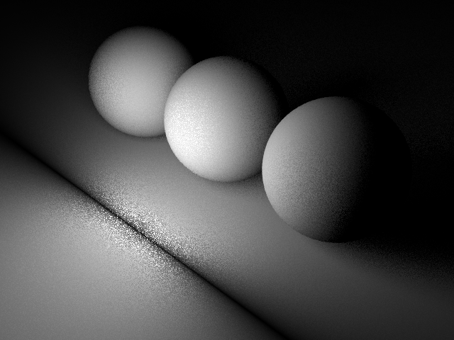
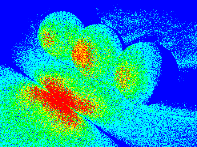
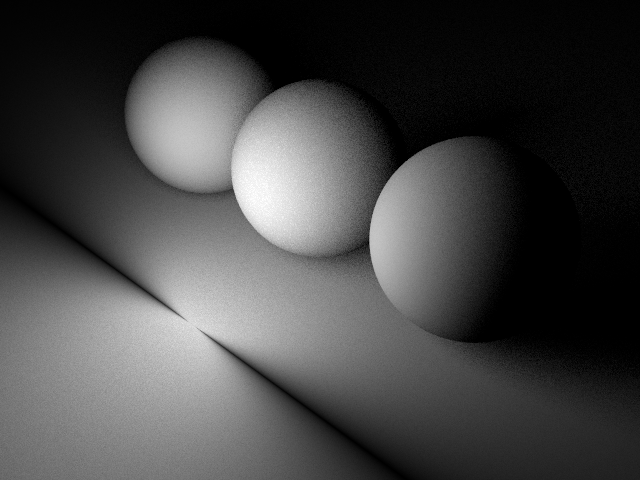
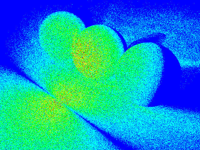
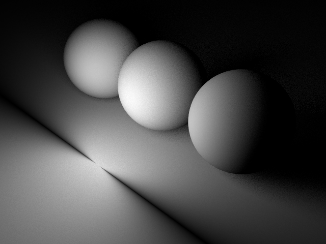
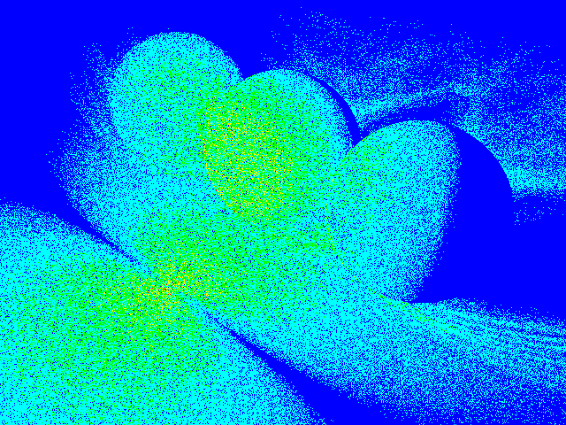
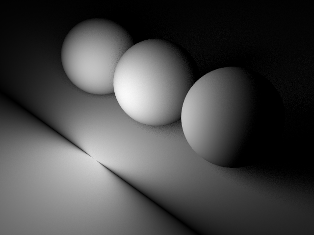
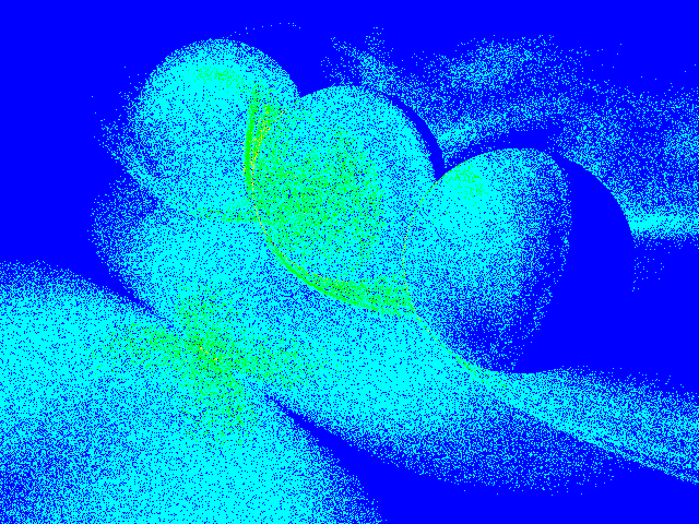
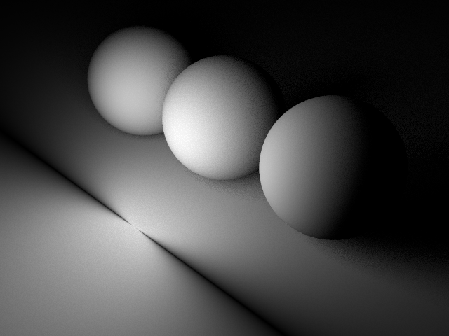
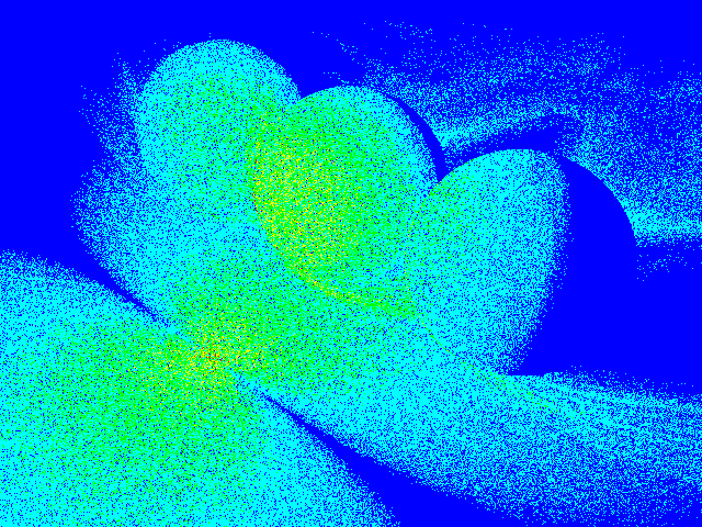
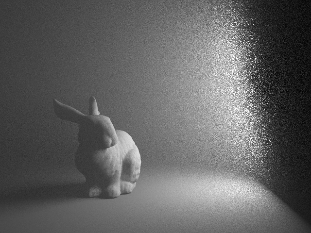
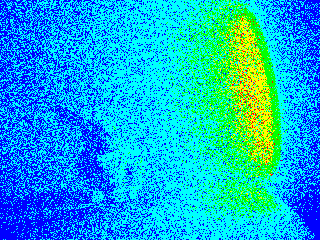
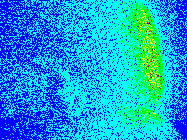
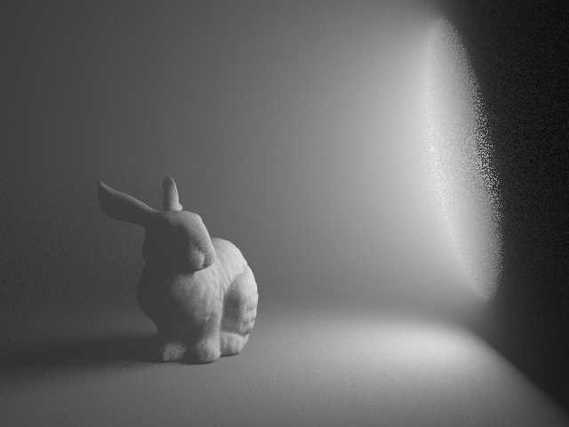
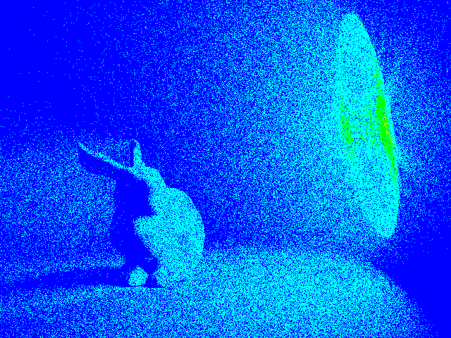
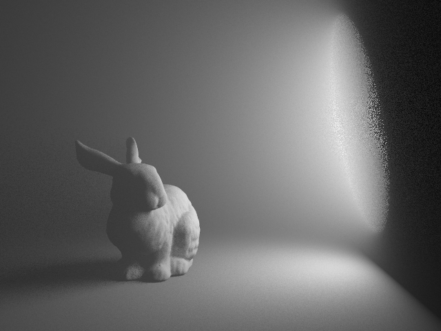
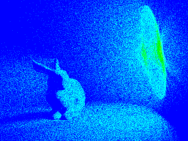
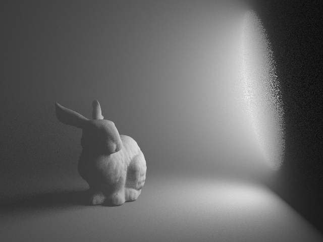
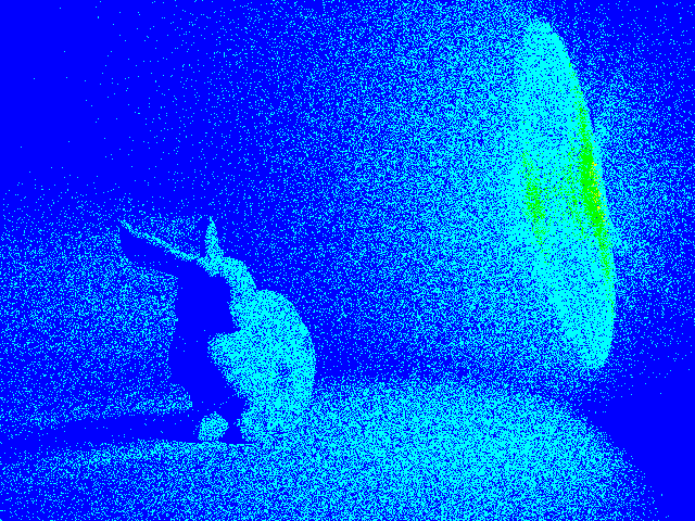
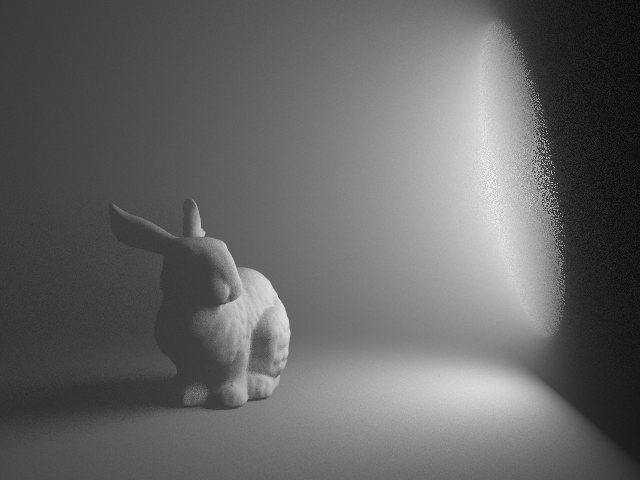
Figures 7 and 8 show a comparison between traditional area sampling [SC97], Gamito’s rejection-based solid angle sampling [Gam16] and our techniques (Mitsuba implementation), without and with the presence of participating media. In both figures only direct illumination (single scattering) is computed, using 16 samples/pixel. Inside a medium, we first sample a point along the ray via equiangular sampling [KF12] w.r.t. the disk light center, and then use the corresponding disk sampling technique to generate a point on the light. In the case of uniform area sampling, a better strategy is to first sample the light surface and then perform equiangular sampling w.r.t. that chosen point. We therefore include this strategy in \Freffig:comparative_media (called “Area sampling (first)”), which is incompatible with the solid angle mappings. The results show that our sampling methods outperform Gamito’s method on surfaces, and perform at least on par in participating media, where variance due to medium sampling dominates when using solid angle sampling. In all cases, area sampling yields much higher variance. In the supplemental document we provide global illumination comparisons between our tabulated radial sampling and Mitsuba’s built-in disk area sampling.
fig:graphs shows a comparison between the convergence and the cost of the different techniques from Figures 7 and 8. For the same number of samples, our mappings produce lower error than Gamito on surfaces and perform virtually identically in media. In terms of cost, our tabulated version is almost as fast as area sampling, and the fully numerical implementation can be up to 10 slower. Note that the performance of the iterative numerical inversion depends on the geometrical configuration: the starting point for the inversion affects the number of iterations required for convergence. The parallel and radial mappings take respectively 1-3 and 1-4 Newton-Raphson iterations in our tests. Also note that in scenes with higher geometric and shading complexity, the relative cost of the different methods has less impact on the overall rendering performance.
Finally, \Freffig:arnold shows a scene rendered in Arnold, comparing our tabulated radial map implementation to the renderer’s built-in uniform area sampling. The scene features many production features, including high-resolution texture maps, fur, displacement, subsurface scattering, indirect surface and volume-to-surface light transport. In such cases the higher cost of our technique has a negligible impact on the total rendering performance. With 256 samples/pixel our tabulated radial map yields a noise-free image, while area sampling suffers from a substantial amount of noise.
6 Conclusions
We have presented two new area-preserving mappings that enable the uniform solid angle sampling of oriented disk light sources. Following the key observation that this solid angle is a spherical ellipse, we make use of the Hat-Box theorem to transform canonical unit-square sample points onto the spherical ellipse in a way that preserves their stratification. To avoid costly numerical inversion, we develop a practical mapping tabulation that introduces little overhead over traditional uniform area sampling [SC97] while significantly reducing the variance of the illumination estimate. Our mappings are also competitive to existing disk solid angle sampling techniques [Gam16], without imposing restrictions on the sample generator.
As a by-product of our work, we have proposed two new expressions for the subtended solid angle of a disk, which in addition to graphics is important in other fields such as particle transport. In this context, most previous analytic formulations [Pax59, TPK∗07, Con10] have included at least two incomplete elliptic integrals that need to be computed numerically. In contrast, our radial formulation, based on Booth’s spherical topology analysis [Boo44], involves only one elliptic integral, making it more simple and practical than previous work.
While this work only considers circular disks, our approach could be extrapolated to other shapes whose subtended solid angle is also an ellipse, such as elliptical disks and ellipsoids [Hei17]. Including these geometries would only require finding the spherical ellipses subtended by them. Moreover, our mappings could reduce variance of other shapes such as cylinders, following Gamito [Gam16].
The main limitation of our method is the lack of analytical inversion of the proposed mappings, which requires using either costly numerical inversion or tabulation. Unfortunately, it seems impossible to find a spherical ellipse mapping that does not involve incomplete elliptic integrals, whose inversion is unknown. The presented mappings also only consider the solid angle, but not the other contribution terms in \Frefeq:rendering, e.g. the BRDF or the foreshortening term. Developing methods for including at least some of these other terms is an interesting direction for future work. Furthermore, while our mappings are nearly optimal for uniformly emitting disk luminaires, it would be interesting to take into account spatially-varying emission profiles, in the spirit of the work of Bitterli et al. [BNJ15].



Acknowledgements
We would like to thank the anonymous reviewers for their suggestions. This project was funded by the European Research Council (ERC Consolidator Grant 682080), DARPA (HR0011-16-C-0025), and the Spanish Ministerio de Economía y Competitividad (TIN2014-61696-EXP, TIN2013-47276-C6-3-R). Jorge López-Moreno was additionally founded by a Juan de la Cierva fellowship. No ellipses were harmed in the making of this paper.
References
- [Arv95] Arvo J.: Stratified sampling of spherical triangles. In Proceedings of SIGGRAPH ‘95 (1995), ACM, pp. 437–438.
- [Arv01] Arvo J.: Stratified sampling of 2-manifolds. SIGGRAPH 2001 Course Notes 29, 2 (2001).
- [BNJ15] Bitterli B., Novák J., Jarosz W.: Portal-masked environment map sampling. Computer Graphics Forum 34, 4 (2015), 13–19.
- [Boo44] Booth J.: On the rectification and quadrature of the spherical ellipse. The London, Edinburgh, and Dublin Philosophical Magazine and Journal of Science 25, 163 (1844), 18–38.
- [Boo52] Booth J.: Researches on the geometrical properties of elliptic integrals. Philosophical Transactions of the Royal Society of London 142 (1852), 311–416.
- [Car95] Carlson B. C.: Numerical computation of real or complex elliptic integrals. Numerical Algorithms 10, 1 (1995), 13–26.
- [Con10] Conway J. T.: Analytical solution for the solid angle subtended at any point by an ellipse via a point source radiation vector potential. Nuclear Instruments and Methods in Physics Research 614, 1 (2010), 17–27.
- [Ebe99] Eberly D.: Perspective projection of an ellipse, 1999.
- [Faj10] Fajardo M.: Ray tracing solution for film production rendering. ACM SIGGRAPH Talks: Global Illumination Across Industries (2010).
- [Gam16] Gamito M. N.: Solid angle sampling of disk and cylinder lights. Computer Graphics Forum 34, 4 (2016).
- [Hei17] Heitz E.: Analytical calculation of the solid angle subtended by an arbitrarily positioned ellipsoid to a point source. Nuclear Instruments and Methods in Physics Research 852 (2017).
- [HKWB09] Hašan M., Křivánek J., Walter B., Bala K.: Virtual spherical lights for many-light rendering of glossy scenes. ACM Trans. Graph. 28, 5 (dec 2009), 143:1–143:6.
- [Jak10] Jakob W.: Mitsuba renderer, 2010. http://www.mitsuba-renderer.org.
- [KF12] Kulla C., Fajardo M.: Importance sampling techniques for path tracing in participating media. Computer Graphics Forum 31, 4 (2012), 1519–1528.
- [Pax59] Paxton F.: Solid angle calculation for a circular disk. Review of Scientific Instruments 30, 4 (1959), 254–258.
- [PSC∗15] Pilleboue A., Singh G., Coeurjolly D., Kazhdan M., Ostromoukhov V.: Variance analysis for Monte Carlo integration. ACM Trans. Graph. 34, 4 (2015), 124.
- [SC97] Shirley P., Chiu K.: A low distortion map between disk and square. Journal of graphics tools 2, 3 (1997), 45–52.
- [SHD15] Simon F., Hanika J., Dachsbacher C.: Rich-VPLs for improving the versatility of many-light methods. Computer Graphics Forum 34, 2 (2015), 575–584.
- [Shi91] Shirley P.: Discrepancy as a quality measure for sample distributions. In Proceedings of Eurographics ‘91 (1991), vol. 91, pp. 183–194.
- [SK13] Subr K., Kautz J.: Fourier analysis of stochastic sampling strategies for assessing bias and variance in integration. ACM Trans. Graph. 32, 4 (jul 2013), 128:1–128:12.
- [SWZ96] Shirley P., Wang C., Zimmerman K.: Monte Carlo techniques for direct lighting calculations. ACM Trans. Graph. 15, 1 (jan 1996), 1–36.
- [TNSP98] Tobler R. F., Neumann L., Sbert M., Purgathofer W.: A new form factor analogy and its application to stochastic global illumination algorithms. In Proceedings of EGSR ‘98 (1998), pp. 35–44.
- [TPK∗07] Timus D., Prata M., Kalla S., Abbas M., Oner F., Galiano E.: Some further analytical results on the solid angle subtended at a point by a circular disk using elliptic integrals. Nuclear Instruments and Methods in Physics Research 580, 1 (2007), 149–152.
- [UFK13] Ureña C., Fajardo M., King A.: An area-preserving parametrization for spherical rectangles. Computer Graphics Forum 32, 4 (2013), 59–66.
- [Ure00] Ureña C.: Computation of irradiance from triangles by adaptive sampling. Computer Graphics Forum 19, 2 (2000), 165–171.
- [Wan92] Wang C.: Physically correct direct lighting for distribution ray tracing. In Graphics Gems III (1992), Academic Press Professional, Inc., pp. 307–313.
Appendix A Derivation of \Frefeq:delta_sin
Here we derive the expression for in \Frefeq:delta_sin, whose integral we then express as a combination of incomplete elliptic integral functions in \Frefeq:urena_int_real. We use the tangent ellipse, shown in \Freffig:tangent-ellipse and introduced in \Frefsec:desarrollo and \Freffig:projection, right. The ellipse semi-axes are aligned with and , respectively.
For any angle , we first obtain a coordinate along the axis. (We only consider , thus , and convert negative to positive using symmetry, as described in \Frefsec:urena_mapping.) Using the ellipse equation , we can get the corresponding coordinate along as a function of :
| (24) |
We then consider the point on the tangent ellipse and its spherical projection . The -coordinate of , and also of its cylindrical projection (see \Freffig:urena_integration, left), is
| (25) |
Substituting \Frefeq:app_y into (25):
| (26) |
where , and are as in \Frefeq:pmc.
Using and , in \Frefeq:app_h1 we can substitute by . With this we can finally write explicitly as a function of :
| (27) |
which is exactly \Frefeq:delta_sin.
Appendix B Derivation of \Frefeq:ellipse radius
Here we derive the expression for in \Frefeq:ellipse radius, which is used in the radial mapping (\Frefsec:ibon_mapping). We consider the planar ellipse resulting from the parallel projection of the spherical ellipse onto the plane. This ellipse’s semi-major and semi-minor axes are and , respectively (see \Freffig:ellipse_quadrant).
Consider a point whose polar coordinates and Cartesian coordinates are related as
| (28) |
We want to define in such a way that is on the planar ellipse curve. Thus, and must obey the ellipse equation, i.e.
| (29) |
We can substitute and from \Frefeq:coord_relation into the ellipse equation, resulting in
| (30) |
We can thus write
| (31) |
which is \Frefeq:ellipse radius.