Stanford, CA 94305, USA
bSLAC National Accelerator Laboratory,
Menlo Park, CA 94025, USA
cNational Institute for Standards and Technology,
Boulder, CO 80305, USA
dSanta Clara University,
Santa Clara, CA 95053, USA
†11email: zeesh@slac.stanford.edu
SLAC Microresonator Radio Frequency (SMuRF) Electronics for Read Out of Frequency-Division-Multiplexed Cryogenic Sensors
Abstract
Large arrays of cryogenic sensors for various imaging applications ranging across x-ray, gamma-ray, Cosmic Microwave Background (CMB), mm/sub-mm, as well as particle detection increasingly rely on superconducting microresonators for high multiplexing factors. These microresonators take the form of microwave SQUIDs that couple to Transition-Edge Sensors (TES) or Microwave Kinetic Inductance Detectors (MKIDs). In principle, such arrays can be read out with vastly scalable software-defined radio using suitable FPGAs, ADCs and DACs. In this work, we share plans and show initial results for SLAC Microresonator Radio Frequency (SMuRF) electronics, a next-generation control and readout system for superconducting microresonators. SMuRF electronics are unique in their implementation of specialized algorithms for closed-loop tone tracking, which consists of fast feedback and feedforward to each resonator’s excitation parameters based on transmission measurements. Closed-loop tone tracking enables improved system linearity, a significant increase in sensor count per readout line, and the possibility of overcoupled resonator designs for enhanced dynamic range. Low-bandwidth prototype electronics were used to demonstrate closed-loop tone tracking on twelve 300-kHz-wide microwave SQUID resonators, spaced at 6 MHz with center frequencies 5–6 GHz. We achieve multi-kHz tracking bandwidth and demonstrate that the noise floor of the electronics is subdominant to the noise intrinsic in the multiplexer.
Keywords:
Microwave SQUIDs, FPGA, tone-tracking, TES, multiplexing, microresonators, MKIDs1 Introduction
The sensitivity of modern CMB bolometric sensors used in ground-based and space-based cameras is photon-noise-limited. Thus a camera’s sensitivity scales approximately as the square root of the number of sensors or of the integration time. To keep integration times reasonable, sensor counts deployed on CMB cameras have been dramatically increasing, from only a handful of sensors two decades ago to a projected nearly 500,000 sensors in CMB-S4 [1]. X-ray imaging spectrometers based on Transition Edge Sensor (TES) microcalorimeters have also increased sensor count in order to increase the photon collection efficiency of the TES array without degrading energy resolution [2].
The sensors are operated at cryogenic temperatures, thus heat load from room-temperature wires must be reduced by multiplexing sensor signals at the cold stages. Common forms of multiplexing for TES bolometers, such as time-division multiplexing using Superconducting Quantum Interference devices (SQUIDs) and amplitude-modulated frequency-division multiplexing, have reached multiplexing factors of 65 in deployed CMB cameras [3, 4, 5].
Superconducting microresonators with resonator frequencies of order 0.1–10 GHz can be excited and probed in the thousands, by coupling to a single RF probe line [6, 7]. The resonators can double as photon sensors in the case of Microwave Kinetic Inductance Detectors (MKIDs), where Cooper-pair breaking by photons influences resonance amplitude and frequency in a measurable way [8]. Alternatively, the resonators can couple to TESs via microwave SQUIDs, which transduce the current changes in the TESs into frequency shifts [9]. In both schemes, the resonators can be excited and read out in large numbers with software-defined radio (SDR) using suitable FPGAs, ADCs and DACs. Several groups are using SDR hardware to develop readout systems for microresonators [10].
This paper will describe a next-generation readout system called the SLAC Microresonator Radio Frequency (SMuRF) electronics specifically designed to read out more than 4,000 channels in 4 GHz of bandwidth (Section 2). SMuRF is unique in that it implements fast tracking of resonances, which reduces the power to the follow-on amplifier, thereby increasing dynamic range or enabling a large multiplexing factor (Section 3). We show that the readout noise of a prototype for SMuRF is subdominant to device noise (Section 4).
2 SMuRF electronics description
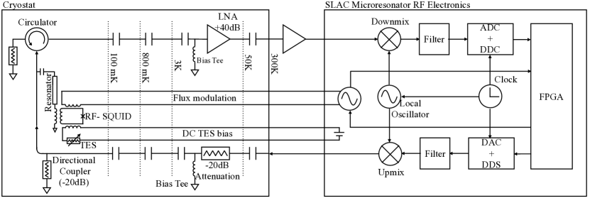
A schematic of the SMuRF readout system with a typical setup of microwave SQUIDs coupled to TESs is shown in Fig. 1. At the heart of the system is an FPGA running firmware for tone generation, tracking, read out and signal demodulation. The system uses a digital I/Q scheme to avoid analog electronic calibration errors. Excitation tones are generated at baseband by the DAC using Direct Digital Synthesis (DDS). Those tones are upmixed to the RF band, sent into the cryostat to probe the resonances, and the transmitted signals are then downmixed to baseband. The ADC uses Digital Down Conversion (DDC) to measure the phase shift of the tones after they interact with the microresonators. An updated frequency is then synthesized in the FPGA to drive each resonator at its new resonant frequency.
2.1 Physical architecture
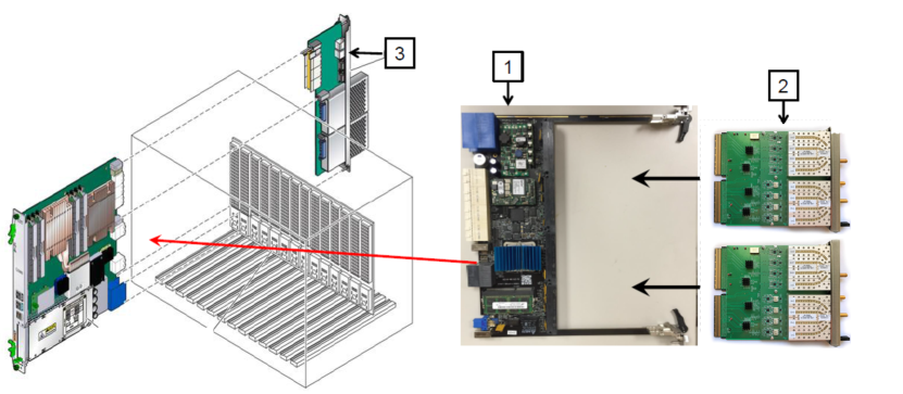
The SMuRF system is built on the Advanced Telecommunication Computing Architecture (ATCA) specification. The physical layout is shown in Fig. 2. The base unit of the SMuRF system is a single slot in an ATCA crate, which houses a carrier card. A carrier card contains a Xilinx Kintex Ultrascale FPGA, DDR memory, connections to a 40 Gbps backplane, and connections to two smaller boards called Advanced Mezzanine Cards (AMCs). The carrier card used for SMuRF was developed at SLAC as part of a “Common FPGA platform” [11].
The FPGA is connected to two AMCs with 16 bi-directional 12.5 Gbit JESD lanes. The AMCs each contain 4 DAC/ADC pairs and local oscillators (LO). Each AMC is connected to a radio frequency (RF) daughter card, which carries bandpass filters and mixers to upconvert the tones to the microresonator band. This is chosen to be on a daughter card to allow flexibility in choosing the microresonator band.
Finally, a rear transition module (RTM) connected to the carrier card via the backplane handles low-frequency functions, including 32 independent TES bias channels and flux biasing for microwave SQUIDs. It also provides stable biases for the low-noise amplifiers in the signal chain. The flux bias can be differentially driven by a slow (20-bit, 1 Ms/s) DAC or a fast (16 bit, 50 Ms/s) DAC, for modulating signals from CMB bolometers and x-ray calorimeters, respectively. For experiments to use SMuRF electronics, a simple, customized interface card with passive analog elements connects wiring between the cryostat and the SMuRF crates. These interface boards will enable setting bias ranges, connectors for the low-frequency wiring, grounding schemes, and low-pass filtering as desired.
2.2 Comb generation
A comb of tones corresponding to resonance frequencies in a 500 MHz block is generated on the FPGA at baseband (750 MHz-1.25 GHz). For each resonator, the FPGA synthesizes a high-amplitude drive tone centered directly on the resonance, and optionally two lower-amplitude sidebands detuned by a half-bandwidth for calibration as necessary. The comb of output tones is played out as a pair of 625 MHz complex timestreams by a 16 bit, 2.5 Gs/s DAC by DDS. Local oscillators (LO) are used to mix the baseband comb up to the microresonator RF frequencies. On-board frequency multiplexers combine 8 such 500-MHz blocks into a single 4 GHz band, which is routed to the cryostat on a single coaxial cable. Upon return to the electronics, the 4 GHz band is channelized into 8 500 MHz bands using bandpass filters. The tones in each band are downmixed to baseband using the same LOs, and digitized and channelized by a 14 bit, 2.5 Gs/s ADC using DDC.
A different choice of LO frequencies and bandpass filters would allow the output tones to access a different RF frequency if the microresonators were, for instance, in the 1–2 GHz band rather than the 4–8 GHz band. Bypassing the mixers would allow direct sampling and excitation of 0.5–1 GHz band resonators.
2.3 Prototype system
A prototype system with a standard SLAC FPGA carrier board, but with ADCs and DACs to manipulate only 150 MHz of bandwidth was assembled to test the tracking algorithms and noise properties. Low-frequency signals, various RF reference signals and filtering and mixing functions in this prototype were performed by benchtop electronics, instead of the compact form factor being developed for the full SMuRF electronics described in Section 2.1. Measurements were performed on two NIST mux16b microwave SQUID chips containing 64 resonances with bandwidths of 300 kHz between 5.0 and 5.5 GHz [12].
3 Tone tracking
A unique feature of the SMuRF electronics is the ability to track resonator dips and adjust excitation tones at high bandwidth. This reduces the power transmitted to the follow-on low-noise amplifier since the tone is always located at the frequency of lowest transmission. This in turn increases the amplifier’s dynamic range, reduces the linearity requirements of the system, and allows more resonances to be read out with the same amplification chain. With the prototype setup we were able to demonstrate fast tone tracking on twelve channels simultaneously.
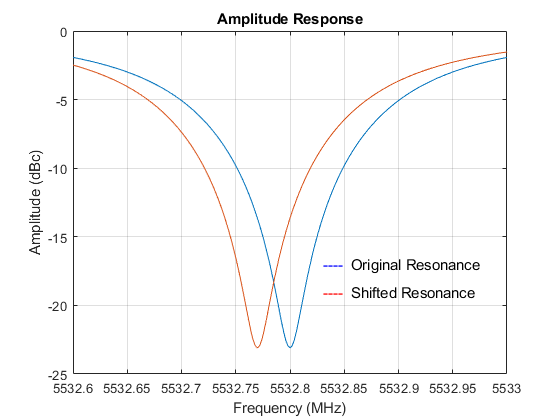
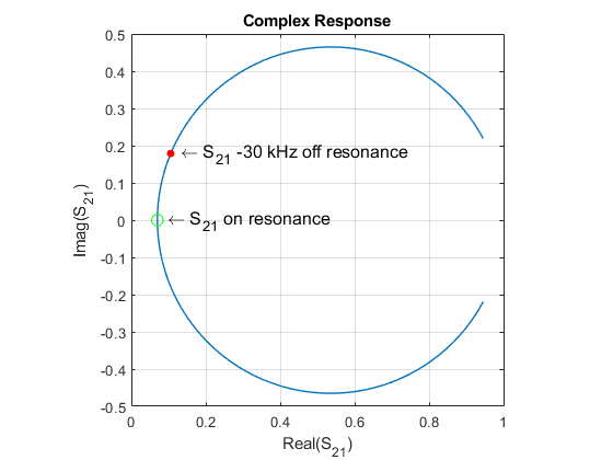
The received signal in a narrow band around each resonance line is demodulated to a complex amplitude. This amplitude is phase-rotated so the quadrature component is proportional to the frequency deviation from the center of the resonance line. The frequency error estimate, updated at 1.3 MHz for each resonance, is input to a feedback loop filter which updates the digitally-generated frequency of each tone used to drive the multiplexer array. Two low-amplitude (20 dB down) sidebands are generated around each line-tracking tone in order to calibrate the phase rotation and scale needed to translate complex amplitude to frequency error. The complex amplitudes of these sidebands, normalized to their generated amplitudes, are averaged to estimate a reference approximating the response of the transmission in the absence of a resonator notch. Initial estimates of resonator parameters are taken either from a network analyzer or amplitude scan with the readout electronics. The process of updating the tones is illustrated in Fig. 3.
3.1 Tone tracking bandwidth
The bandwidth of the tone tracking algorithm was measured for the prototype electronics by abruptly changing the frequency of the center tone and recording the response. The bandwidth was measured to be about 20 kHz. This was limited by the algorithmic latency of the prototype system and can be improved.
While 20 kHz tone tracking is adequate for most CMB applications, the x-ray applications need a bandwidth of closer to 1 MHz. A feed-forward algorithm is being developed in which the resonator movements are predicted for flux bias at MHz speed and the tones are updated at that rate, while the feedback occurs at a slower rate.
3.2 Reduction of power
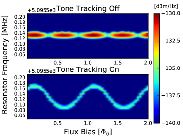
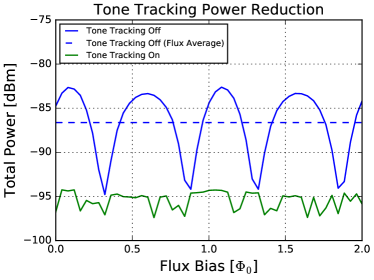
Tone tracking enables most of the drive power to be reflected away from the input of the HEMT amplifier. To demonstrate the improved linearity of the system in closed-loop mode, power at the HEMT input was measured while a sawtooth flux bias of amplitude was applied to the common flux bias line. This modulated all resonance frequencies simultaneously. The drive tones follow resonators as they shift, and the power transmitted to the HEMT input remains constant as a function of flux bias. In open-loop mode, the drive tones are held fixed at the flux-averaged frequency centers of the resonators, and the resonators shift past the drive tones, as shown in Fig. 4. Averaged over a flux bias period, the power per resonance is 9 dB lower in closed-loop mode for this set of resonators, as expected.
4 Noise performance
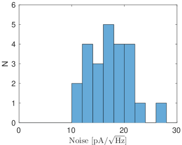
Because the prototype was not optimized for phase noise, we did not evaluate it directly, but this is an important measurement for the full 4 GHz bandwidth SMuRF system. We did, however, characterize the system noise of the prototype running closed-loop tone tracking on mux16b microwave SQUID multiplexers. The noise was measured with a DC flux bias and referred to the input current using the slope of the SQUID response curve and the relative mutual inductance of the input line compared to the flux bias line. This is more sensitive to input current than when averaged over a period of AC flux bias. The measured noise, seen in Fig. 5, is between 10–20 pA/ as observed in measurements of the same type of chips in other systems [12].
5 Conclusion
Using an early prototype of SMuRF electronics we have demonstrated tone tracking over wide RF bandwidth suitable for CMB camera readout. Tone tracking is unique to the SMuRF system and significantly reduces the linearity requirements on the cold and warm readout, potentially enabling larger multiplexing factors than achievable with otherwise comparable systems. The first full SMuRF system is being assembled now and is being designed to read out more than 4000 channels in 4 GHz of bandwidth.
Acknowledgements.
This work was supported by the Department of Energy Office of Science Detector R&D funds.References
- 1 M. H. Abitbol, Z. Ahmed, D. Barron, R. B. Thakur, A. N. Bender, B. A. Benson, et al., “CMB-S4 Technology Book,” arXiv preprint arXiv:1706.02464, 2017.
- 2 J. N. Ullom and D. A. Bennett, “Review of superconducting transition-edge sensors for x-ray and gamma-ray spectroscopy,” Superconductor Science and Technology, vol. 28, no. 8, p. 084003, 2015.
- 3 M. Dobbs, M. Halpern, K. D. Irwin, A. T. Lee, J. Mates, and B. A. Mazin, “Multiplexed readout of CMB polarimeters,” in Journal of Physics: Conference Series, vol. 155, p. 012004, IOP Publishing, 2009.
- 4 B. Benson, P. Ade, Z. Ahmed, S. Allen, K. Arnold, J. Austermann, A. Bender, L. Bleem, J. Carlstrom, C. Chang, et al., “SPT-3G: a next-generation cosmic microwave background polarization experiment on the South Pole telescope,” in SPIE Astronomical Telescopes+ Instrumentation, pp. 91531P–91531P, International Society for Optics and Photonics, 2014.
- 5 S. W. Henderson, R. Allison, J. Austermann, T. Baildon, N. Battaglia, J. A. Beall, D. Becker, F. De Bernardis, J. R. Bond, E. Calabrese, S. K. Choi, K. P. Coughlin, K. T. Crowley, R. Datta, M. J. Devlin, S. M. Duff, R. Dunner, J. Dunkley, A. van Engelen, P. A. Gallardo, E. Grace, M. Hasselfield, F. Hills, G. C. Hilton, A. D. Hincks, R. Hlozek, S. P. Ho, J. Hubmayr, K. Huffenberger, J. P. Hughes, K. D. Irwin, B. J. Koopman, A. B. Kosowsky, D. Li, J. McMahon, C. Munson, F. Nati, L. Newburgh, M. D. Niemack, P. Niraula, L. A. Page, C. G. Pappas, M. Salatino, A. Schillaci, B. L. Schmitt, N. Sehgal, B. D. Sherwin, J. L. Sievers, S. M. Simon, D. N. Spergel, S. T. Staggs, J. R. Stevens, R. Thornton, J. Van Lanen, E. M. Vavagiakis, J. T. Ward, and E. J. Wollack, “Advanced ACTPol Cryogenic Detector Arrays and Readout,” p. 9, oct 2015.
- 6 J. Zmuidzinas, “Superconducting microresonators: Physics and applications,” Annual Review of Condensed Matter Physics, vol. 3, no. 1, pp. 169–214, 2012.
- 7 K. D. Irwin, “Shannon limits for low-temperature detector readout,” in AIP Conference Proceedings, vol. 1185, pp. 229–236, AIP, 2009.
- 8 P. K. Day, H. G. LeDuc, B. A. Mazin, A. Vayonakis, and J. Zmuidzinas, “A broadband superconducting detector suitable for use in large arrays,” Nature, vol. 425, pp. 817–821, Oct. 2003.
- 9 J. A. B. Mates, G. C. Hilton, K. D. Irwin, L. R. Vale, and K. W. Lehnert, “Demonstration of a multiplexer of dissipationless superconducting quantum interference devices,” Applied Physics Letters, vol. 92, p. 023514, jan 2008.
- 10 D. Werthimer, “The CASPER collaboration for high-performance open source digital radio astronomy instrumentation,” in General Assembly and Scientific Symposium, 2011 XXXth URSI, pp. 1–4, IEEE, 2011.
- 11 R. Herbst, R. Claus, M. Freytag, G. Haller, M. Huffer, S. Maldonado, K. Nishimura, C. O’Grady, J. Panetta, A. Perazzo, et al., “Design of the SLAC RCE Platform: A general purpose ATCA based data acquisition system,” in Nuclear Science Symposium and Medical Imaging Conference (NSS/MIC), 2014 IEEE, pp. 1–4, IEEE, 2014.
- 12 B. Dober, D. T. Becker, D. A. Bennett, S. A. Bryan, S. M. Duff, J. D. Gard, J. P. Hays-Wehle, G. C. Hilton, J. Hubmayr, C. D. Reintsema, L. R. Vale, and J. N. Ullom, “Microwave SQUID Multiplexer for Cosmic Microwave Background Imagers,” ArXiv e-prints, Oct. 2017.