Visiting Newton’s Atelier Before the Principia, 1679-1684.
Abstract.
The manuscripts that presumably contained Newton’s early development of the fundamental concepts that led to his Principia have been lost. A plausible reconstruction of this development is presented based on Newton’s exchange of letters with Robert Hooke in 1679, with Edmund Halley in 1686, and on some clues in the diagram associated with Proposition1 in Book1 of the Principia that have been ignored in the past. The graphical method associated with this proposition leads to a rapidly convergent method to obtain orbital curves for central forces, and elucidates how Newton may have have been led to formulate some of his other propositions in the Principia. .
1. Introduction
The publication of Newton’s masterpiece, “Mathematical Principles of Natural Philosophy” known as Principia [1], marks the beginning of modern theoretical Physics and Astronomy. It was regarded as a very difficult book by his contemporaries, and also by modern readers. In 1687 when the Principia was first published, it was claimed that only a handful of readers in Europe were competent to read it [2]. John Locke, for example, found the demonstrations impenetrable, and asked Christiaan Huygens if he could trust them. When Huygens assured him that he could, “he applied himself to the prose and digested the physics without the mathematics” [3]. Shortly after the release of the Principia a group of students at Cambridge supposedly were heard by Newton to say, “here goes a man who has written a book that neither he nor anyone else understands” [4]. Newton himself remarked that “ to avoid being baited by little Smatterers in Mathematicks . . . he designedly made his Principia abstruse; but yet as to be understood by able Mathematicians” [5]
Presumably one person he had in mind was Robert Hooke, with whom he had often quarreled. But shortly after viewing an early draft of the Principia, entitled De Motu Corporum Gyrum, that Newton had sent to the Royal Society in 1685 [6], Hooke understood that Newton had implemented mathematically his own concept of orbital dynamics that he had communicated to Newton in a correspondence in 1679. Hooke promptly applied the first theorem in De Motu, and in an unpublished manuscript dated Sept 1685, he showed graphically and analytically that for a central attractive force depending linearly on the distance from the center, the resulting orbit is an ellipse [7],[8]. Newton described his concepts in a geometrical language rather than in the analytic calculus that he and Gottfried Leibniz had developed. At the time that the Principia was first published (1687) this approach made sense, because the calculus, first published by Leibniz in 1684, was hardly known, and Newton did not published his own version (Fluxions) in full until 1704. It has been argued that Newton’s geometrical descriptions were also the way in which he originally discovered and developed his fundamental dynamical concepts [9]. This view will be supported here. It is also claimed that the Principia is replete with mathematical abstractions and incomprehensible geometrical diagrams [10]. Even Richard Feynman remarked that he could not follow Newton’s demonstration in Proposition 11 (Principia, Book 1) that elliptical orbits imply an inverse square central force [11]. But these difficulties are often overemphasized. It will be shown that with an elementary knowledge of geometry, Proposition 1, one of the most fundamental theorems on which the Principia is based, can be applied as a graphical method to construct approximate orbits that describe the dynamical effect of central forces.
There is considerable evidence that a major progress in Newton’s understanding of orbital dynamics occurred in 1679 through his correspondence with Robert Hooke, who described to Newton his concept for the physical basis of planetary motion. Hooke viewed the origin of the motion of planets around the Sun by the compounding of inertial motion with periodic gravitational impacts towards the Sun. This concept was the link missing before Newton could develop his earlier dynamical concepts further [13]. In a letter to Newton on Nov. 24,1679, Hooke wrote, “For my own part I shall take it as a great favour if you please to communicate by Letter your objections against any hypothesis or opinion of mine, And particularly if you will let me know your thoughts of that of compounding the celestiall motion of the planetts of a direct motion by the tangents and an attractive motion toward the central body” [14].
Hooke had elaborated his dynamical ideas in a short tract, published in 1674, entitled “An attempt to prove the motion the motion of the Earth by observations” [15]. He argued that attractive gravitational forces were universal, and regarding terrestrial gravitation he wrote: “This propagated Pulse I take it to be the Cause of the descent of bodies towards the Earth . . . Suppose for Instance there should be 1000 of these Pulses in a second of Time, then must the Grave body receive all those thousand impressions within the space of time of that Second, and a thousand more the next . . .” [16], [17]. In his letter to Newton he did not specify that the gravitational force could be regarded as a sequence of impacts, but there is evidence that Newton was familiar with Hooke’s 1674 tract. In a letter to Halley on July 14, 1686, Newton admitted that: “This is true, that his Letters occasioned my finding the method of determining Figures which when I tried in the Ellipsis, I threw the calculation by being upon other studies & so it rested for about 5 years till upon your request I sought for yt paper, & not finding it did it again and reduced it into ye Proposition shown you for Mr. Paget . . .”[18]
Newton’s new “method of determining Figures” appeared in the first Theorem of De Motu and in Proposition of the Principia, Book 1, where it is presented, however, in the formal mathematical language of a theorem and its proof, instead of as a graphical method to obtain orbital curves under the action of a central attractive force. This theorem as it appeared in De Motu states that“All orbiting bodies describe, by radii drawn to their centre, areas proportional to their times” [19]. For planetary motion, this relation, known empirically by astronomers as the “area law”, was originally conjectured by Kepler from the observations of planetary motion by Tycho Brahe, but without any dynamical understanding of its origin. For the special case of a circular orbit transversed with constant velocity, the area law follows from the relation between the circumference and the area of the circle, shown first by Archimedes. In effect, Newton’s geometrical construction is a generalization of Archimedes’ construction that approximates a general curve by an inscribed polygon subdivided into triangles of equal areas with a common center.
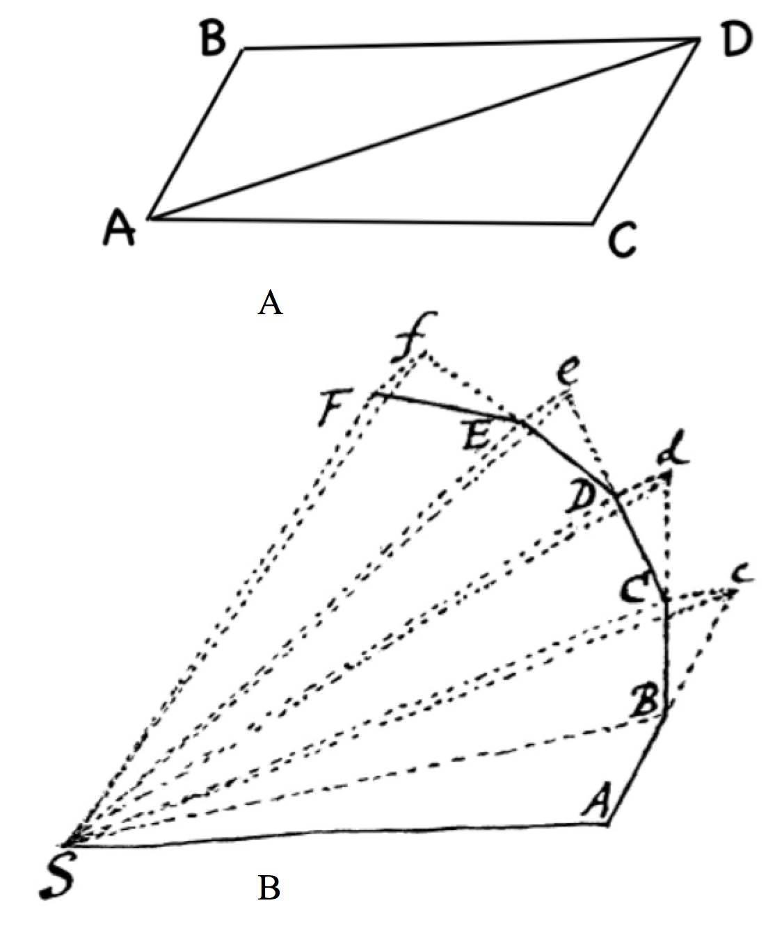
The simplest case of Newton’s geometrical construction of orbital curves by the action of periodic central force impacts is for constant impacts. As Newton wrote to Halley on May 27, 1686, “the simplest case for computation, which was that of Gravity uniform in a medium not Resisting” [20]. This remark, however, has puzzled historians of science aware that a constant central attractive force does not have a simple analytic solution [21] But to obtain such a discrete orbit for periodic impacts graphically , all that is needed is a ruler and a pencil. Indeed, an examination of Newton’s diagram for Theorem 1 in De Motu and for Proposition 1 in the Principia, shows that both were carefully drawn to scale, for the special case of constant impacts. In the resulting diagram in De Motu, reproduced in Fig.1, and in a somewhat different diagram in the Principia, he presented only the discrete orbit resulting for the first four impacts, which was perfectly adequate as an illustration for his theorem or proposition [22]. But it would be highly unlikely that he would not have followed his drawing with further steps as he had done earlier for the case of a constant central force by his curvature method [13], and compare the results from his two distinct methods (see Fig. 4, panels A and B).
When discussing the continuum limit of infinitesimal triangles in Proposition 1, Newton referred to Lemma 3, Corollary 4, indicating that the lines representing the impacts in his diagram ended on a given curve representing the continuum orbit. But this curve does not appear in Newton’s diagram. Moreover, for finite impacts the length of these impact lines would not scale with the radial dependence under consideration. It will be shown that to keep the local radius of curvature of the continuous orbital curve constant, the magnitude of the impact lines vary quadratically relative to the magnitude of the inertial lines (Section 2, Eq. 7). In this case the convergence of the resulting discrete polygon to a continuous orbital curve occurs rapidly.
A bonus from the graphical method to obtain a polygonal approximation for the orbital curve resulting from central force impacts is that it also gives the time elapsed to reach each vertex of the polygon, This time is proportional to the number of vertices from the initial vertex of the orbit. Then the approximate velocity at each vertex is obtained by dividing the average displacement from two adjacent vertices by the periodic time between impacts. In the Principia, the orbital curve and elapsed time can be obtained “granting the quadrature of curvilinear figures”, meaning, by evaluating the two integrals given in in Proposition 41, Problem 28, which in general has to be done numerically. There is not even a hint that it can also be obtained by a graphical method.
Following Newton’s graphical construction, in Section 2 orbital curves are obtained with the initial variables scaled according to the diagrams in De Motu, and in the Principia. For the case of constant impacts, the results are in good agreement with Newton’s earlier approximate graphical calculation based on his curvature method [13] - see Fig.4, panels A amd B - and with an experiment of a ball rolling in an inverted cone - see Fig. 4 panels C and D - carried out also by Hooke [8]. Hooke’s graphical construction for the case that the impacts vary linearly with the distance from a fixed center is shown in Fig.6, panel A. But with the same initial conditions, I found that the corresponding graphical construction for impacts that vary inversely with the square of the distance from the center, shown in Fig.6, panel B, fail to converge [27] . Section 3 contains a discussion of the convergence of the the discrete orbital curves to the continuum limit, and Section 4 contains a summary and some conclusions.
2. Graphical method to construct orbittal curves by Proposition 1
Newton’s recipe to construct graphically a discrete orbit under the action of periodic impacts as described in Theorem 1 of De Motu, and later in Proposition 1, Principia, Book 1, is as follows:
Referring to Fig.1, panel B, for the diagram that appeared in De Motu, SA is the initial distance of a body at A from the center of force at S, and AB is the straight line it transverses at a constant velocity during an interval of time . When it reaches the point B the body receives an impact towards S corresponding in the continuum limit to an acceleration , changing instantaneously its velocity by an amount in this direction. During the next time interval, if the body had started from rest, it would transverse the distance corresponding to in the diagram. But the actual distance transversed and its direction is BC, obtained by compounding (adding vectorially) these two velocities. This law of compounding velocities is shown in Fig.1, panel A. for two simultaneous impacts in the directions AB and AC leading to the displacement AD. The line BC is obtained graphically by extending the line AB to c with Bc=AB, drawing Cc from c parallel to SB, and joining B to C.
This graphical operation is then repeated successively leading to the result shown for constant impacts in the diagram for Theorem 1 in De Motu , Fig.1, panel B obtaining the vertices C,D,E and F. An illustration how and additional step is obtained is shown in Fig.2, panels A,B,C,D and the result for 11 additional inpacts is shown in panel E.
For convenience in notation, let and . Then
| (1) |
and setting for the magnitude of the velocity change due to the component of the impact tangential to the local motion
| (2) |
which can be expressed by a quantity with the dimension of acceleration,
| (3) |
Substituting this expression in Eq.2,
| (4) |
To express graphically as a length, the time interval in this relation is replaced by , Eq.1, and
| (5) |
Finally, replacing by the product of times a length corresponding the local radius of curvature of the continuous orbit at B,
| (6) |
and we have
| (7) |
The relation given in Eq.7, indicating that depends quadratically on , is very important to obtain improved discrete approximations for the orbit in the continuum limit. For example, if the initial magnitude of is decreased by a factor , should be decreased by a factor , and the number of steps required to reach a comparable point of the discrete orbit is approximately doubled. Although the value of is not known a priori, it is not required for the graphical calculation, but it can be evaluated approximately at a given vertex as the radius of a circle that contains this vertex and the two adjacent ones. Newton discussed the radius of curvature of orbital curves in Proposition 6, and in Lemma 11 in the Principia, Book 1.
Given the initial displacement , the initial value of depends on the magnitude of the impact and can be determined by Eq. 7 if the local curvature of the orbit at A is known. In the diagram in Fig. 1, which evidently Newton drew carefully and to scale, he chose the displacement approximately the length of AB=d. Subsequent values of , e.g. , are determined by the graphical construction and the dependence of the magnitude of the impacts on the distances of the vertices from center of force at . For example, assuming a power law dependence of the impacts on distance with exponent , the impact at is related to the previous impact at B by the relation , and more generally,
| (8) |
for the magnitude of the impact at any vertex F. For impacts independent of distance, , for a linear dependence on distance, , and for an inverse square dependence . Newton’s diagram in de Motu, shown in Fig. 1, and the corresponding diagram in Principia were carefully drawn to scale for constant impacts, . This is the “simplest case” for this graphical computation as Newton pointed out to Halley in 1685 (see the quotation in the Introduction), because it avoids the need of an algebraic computation of Eq.8 at each vertex of the discrete orbit .
Regardless of the dependence of the impacts on distance, Newton gave an elementary proof that the areas of successive triangles obtained by joining the ends of the straight lines between impacts to the center at S are all equal. Since by construction, these lines are path lengths transversed at equal time intervals and constant velocity, the areas enclosed by the corresponding polygonal path and the center of force are proportional to the time. This is Newton’s proof of the area law theorem in Proposition 1 quoted in the Introduction.
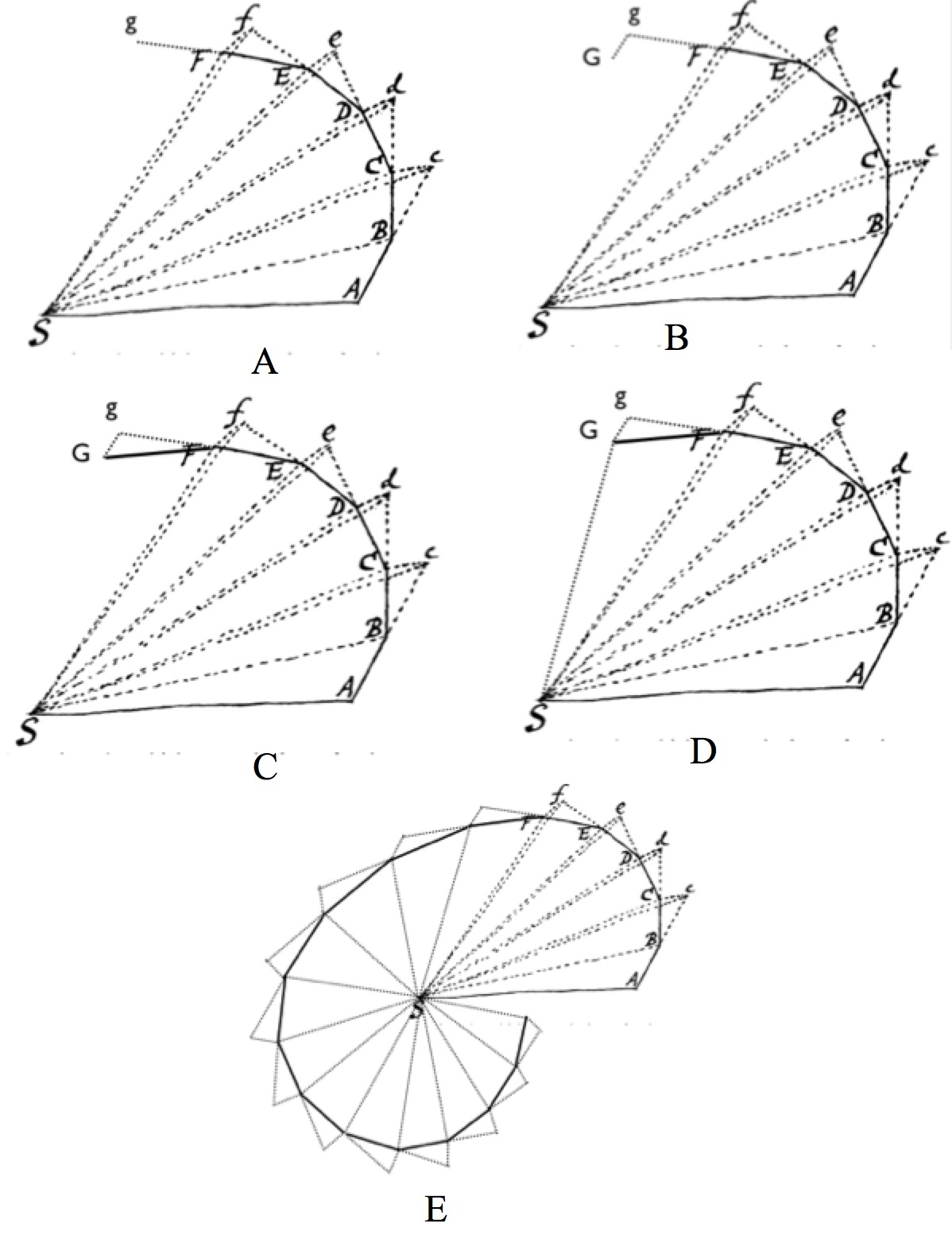
Although Newton’s diagram in Prop.1 was drawn to scale for only 4 equal impacts, it is very likely that he would have continued this graphical construction for more steps as shown in Figs 2 and 3. In Fig. 2, panels A,B,C and D illustrates how the extension of one triangle at the end of vertex F of this diagram is obtained: Taking E as the initial starting point, panel A illustrates the first step, drawing the line Fg equal in length and direction to EF, panel B the impact length Gg drawn equal in length to the other impacts and parallel to SF, panel C the line joining G an F for the displacement GF, and panel D the line SG for the distance and direction at G. Panel E shows the resulting discrete orbit for 11 more impacts. It is very likely that Newton would have carried out this graphical extension, but there isn’t any manuscript evidence for it [23].
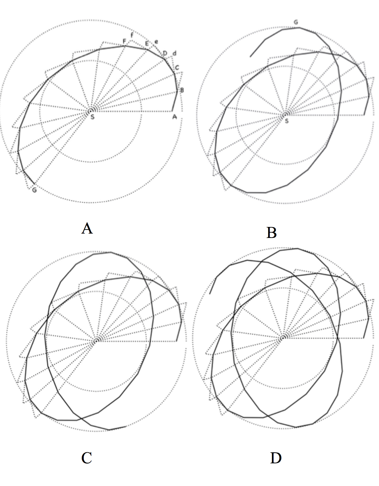
Newton’s graphical construction for constant impacts is continued for additional impacts, and the results are shown in Fig. 3, panels A, B, C, and D. These diagrams show that the orbit has the shape of an ellipse with its axis rotating clockwise about the center of force (impacts), Panel B shows that the next branch of this orbit can be obtained by a reflection about the axis GS indicated in panel A, and similarly in panels C and D. This orbit is confined between two circles with radii corresponding to the nearest and farthest distance of the orbit from the center of force. This restriction is due to the time reversal property of this graphical construction that will not be discussed here.
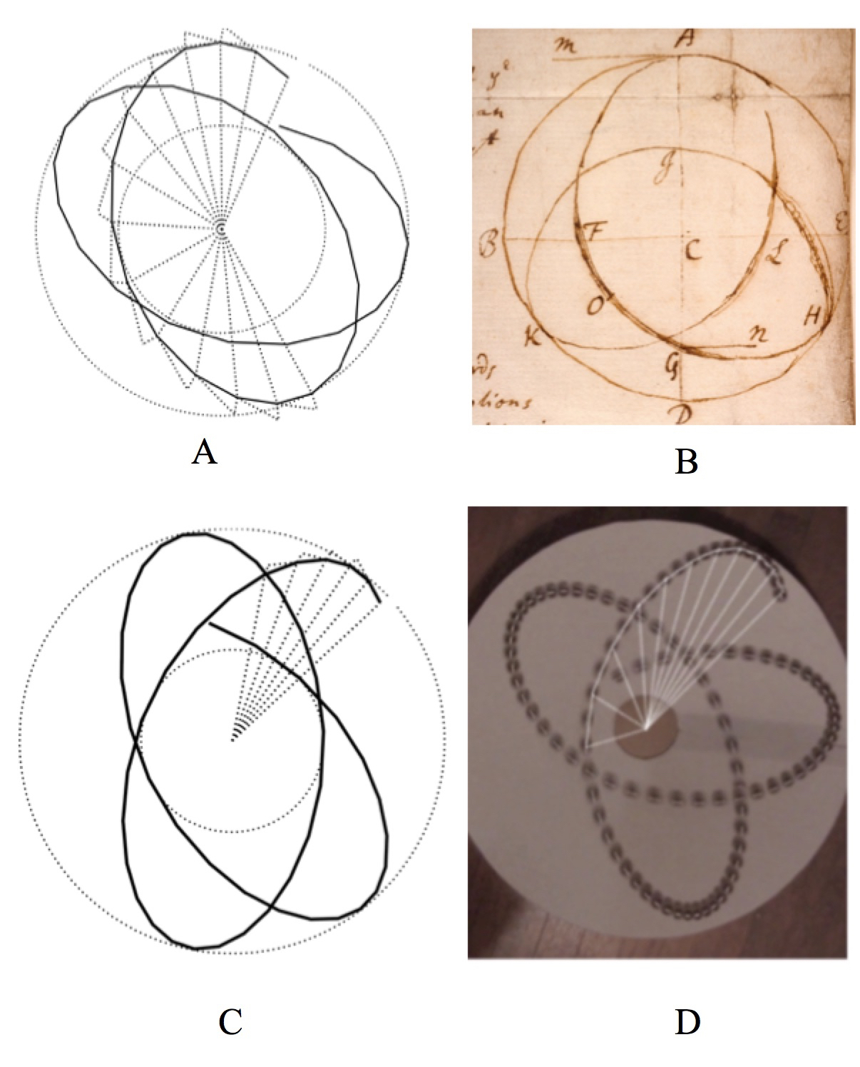
Fig. 4, panel A shows the similarity of the discrete orbital curve obtained with constant impacts, and the diagram in panel B of a figure that Newton included in a letter to Hooke, dated Dec.13, 1679. Newton sent Hooke the diagram shown in this panel , without describing how he had obtained it except for a short comment that “I here consider motion according to the method of indivisibles” [24]. Hooke promptly responded that “Your calculation of the Curve by a body attracted by an equall power at all Distance from the Center Such as a ball Rouling in an inverted Concave Cone is right, and the two auges will not unite for about a third of a Revolution ” [25], [26]. Evidently this experiment had been carried out by Hooke who became very excited after learning that Newton had been able to calculate the corresponding orbit by an appproximate graphical method [27]. At the time Newton could not have implemented the impact approach, because, by his own admission, he had developed it only after his correspondence with Hooke. An alternative approach to obtain the diagram in panel B was based on the local curvature of an orbital curve also developed independently by Christiaan Huygens [13]. Panel D shows a stroboscopic view of an experiment [28] with a ball rolling inside an inverted cone. In this case the radial force is approximately constant, and the radial lines for the first 11 consecutive position have been drawn to illustrate Kepler’s Area Law (conservation of angular momentum). Panel C shows the orbital curve obtained graphically for constant impacts with similar initial conditions. The differences from the experimental orbit is partly due to friction which is evident by the decrease in the maximum displacement of this trajectory from its center.
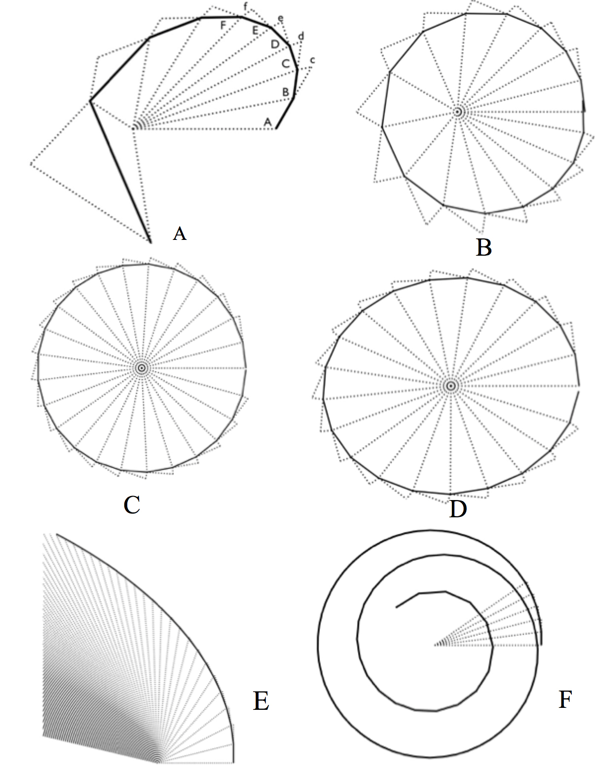
Fig. 5, panel A, shows the resulting discrete orbit when the impacts are scaled according to an inverse square force, starting with the same initial conditions for constant impacts in the De Motu diagram. After the eight impact, the orbit gets too close to the center of force and starts to diverge. Panel B shows a discrete elliptical orbit with the center of force at a focus of the ellipse. It is obtained when the initial displacement is inclined at an angle that gives an isosceles triangle in the first step of the graphical construction. For congruent isosceles triangles associated with the impact length the resulting orbit the graphical construction gives a circular orbit shown in panel C . Panel D shows a discrete elliptical orbit for impacts linear dependent on the distance from the center of the ellipse. Panel E shows a discrete hyperbolic orbit for inverse square force. The envelope of the radial lines at the bottom of this figure indicates the direction of its asymptote. Panel F shows an inward spiraling orbit resulting for the inverse cube force. A the end of his Dec. 13, 1679 letter to Hooke, Newton remarked “for the increased of gravity in the descent may be supposed such that the body shall by an infinite number of spiral revolutions descend continually till it cross the center by motion transcendentally swift”[24]. Evidently, at the time Newton was already aware that for an inverse cube force the orbits do not remain confined. Later, in Proposition 9 in the Principia, he gave a proof that for a spiral orbit, “the centripetal force is inversely as the cube of the distance (from the center) SP”[29].
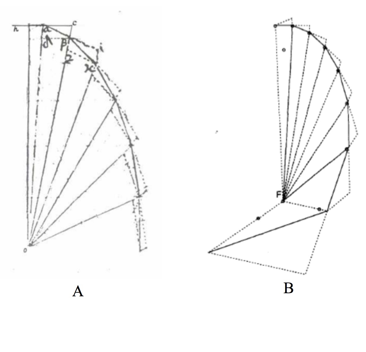
Fig. 6, panel A, shows the upper right hand part of a diagram in a manuscript by Hooke, dated Sept.1685, two years before the publication of the Principia. It represents a discrete orbit obtained with Newton’s graphical procedure, for a body rotating clockwise under the action of a sequence of impacts towards the center at O, that depend linearly on the distance to this center. The resulting vertices of this discrete orbit lie on an ellipse with the center of force at the center of the ellipse. An analytic proof of this result was also given by Hooke[27]. Panel B is the diagram I obtained for an inverse square force with initial conditions equal to those in Hooke’s diagram. For the first 7 steps the discrete orbit approximates closely to an ellipse, as shown by dots in this diagram, with a focus at F, the center of force. But after the discrete orbit approaches closely to F, in the next two steps the impact lengths increase too rapidly as was the case with Newton’s orbit shown in Fig. 5, panel A, and the graphical construction diverges. It is likely that Hooke also carried out this graphical calculation, and perhaps discouraged by this divergence, he failed to publish his results.
3. Summary and Conclusions
It has been shown that Newton’s geometric proof of Kepler’s Area Law in Theorem 1 in De Motu, and in Proposition 1 of the Principia, Book 1, also describes a graphical method to obtain approximate orbits under the action of central forces. When Newton sent De Motu to the Royal Society in 1684, Hooke, who was at the time the secretary of the RS, obtained the copy[6], and recognized that Newton had implemented geometrically his concept of planetary motion - compounding inertial motion with a gravitational attraction towards the Sun. A manuscript dated Sept 1685 in the collection of his papers in the Trinity College Library in Cambridge, shows that Hooke promptly applied Newton’s graphical construction to obtain a discrete orbit under the action of central force impacts that depend linearly on the distance from a fixed center (see Fig. 6, panel A) [7], [8]. He also gave an analytic proof that the vertices of the resulting polygonal orbit lie on an ellipse with the center of the attractive force located at the center of this ellipse. He had observed this orbit with a pendulum, but I could not find any evidence among his papers in this library that he also tried to evaluate the discrete orbit resulting for the gravitational inverse square force. Had he carried it out with his previous initial conditions, he would have found that the graphical procedure fails when the vertices of the discrete orbit approach too closely to the center of force, as shown in my graphical calculation in Fig. 6, panel B. The same problem occurs also if one starts with Newton’s initial conditions, as shown in Fig.5, panel A. It is plausible that Hooke carried out this calculation, but could not figure out the source of this problem, and for this reason did not publish his results.
On Nov 24, 1679 Hooke communicated to Newton his physical concept for the orbital motion under the gravitational action of a central force. It appears to be very unlikely that after Newton implemented Hooke’s concept geometrically, that he would not apply his construction, as Hooke did in 1685, to obtain such orbits graphically. In particular for the simplest case of constant impacts, Newton’s initial condition in the diagrams associate with Theorem 1 in De Motu and with Proposition 1 in the Principia, leads to an approximate discrete orbit shown in Fig. 2, panel E, and in Fig. 3, panel A. This orbit is in good agreement with the result that he had shown to Hooke on Dec 13, 1679, (see Fig 3, panel C) which I conjectured was obtained by a different graphical method based on the concept of curvature developed independently by Huygens[13]. In De Motu and in the Principia, Newton’ diagrams are shown only for four impacts which was adequate to illustrate his proof of Kepler’s Area Law, see Fig.1 panel B. In both cases these diagrams were drawn carefully to scale for the case of constant impacts, and one expects that Newton would have been interested in comparing the resulting discrete orbit with further impacts shown in Fig.4, panel A , with his earlier calculation shown Fig. 4, panel B.. This orbit looks like an ellipse with its axis rotating uniformly, and most likely was also the inspiration for his remarkable Proposition 45, in the Principia, Book1, that states: “ It is required to find the motion of the apsides of orbits that differ very little from circles” [29].
When Halley wrote to Newton that Hooke wanted his contributions to be acknowledged in the Principia, Newton angrily replied: “ For tis plain by his words he knew not how to go about it. Now is this not very fine? Mathematicians that find out, settle & do all the business must consent themselves with being nothing but dry calculators & drudges & another that does nothing but pretend & grasps at all things must carry away all the invention . . .[30]. During a visit at Halley’s, Hooke met Newton and reported in his diary“vainly pretended claim yet acknowledge my information, Interest has no conscience ”[31].
Had Newton chosen to describe Proposition 1 in the Principia not only as a mathematical proof of Kepler’s area law, but also as a graphical method to calculate approximately orbits for central forces, and had he also given for illustration some examples as those shown here, it would have made his book accessible to a large number of readers familiar with elementary geometry. But he chose otherwise, presumably “to avoid being baited by little Smatterers in Mathematicks ”[5]. Moreover, I have shown that the initial lines in his diagrams for Theorem 1 in De Motu, and in Proposition 1 in Principia lead after only a few steps to a divergent orbit for impacts that vary inversely with the square of the distance from the center.(see Fig 5, panel A). Were Newton’s choices of initial parameters in his diagram for Proposition 1 made to discourage little Smatterers in mathematics? Hooke also found such a divergence with his own choice of initial conditions (see Fig. 6 panel B), and presumably became discouraged from pursuing his graphical constructions further[8], [32].
In his introduction to Newton’s Principia, the eminent Newtonian scholar I. B. Cohen asks: “Whatever happened to the work-sheets of the Principia? Do they still exist in some obscure private or public collection? Was this particular set of manuscripts - alone of all the Newton papers - lost or mislaid, either when the Portsmouth Collection was still in Hurstbourne Castle or during the actual transfer to the University Library in Cambridge? Did such work-sheets still exist among Newton’s papers at the time of his death? Or were they lost or destroyed - either by chance or design - during Newton’s own lifetime? We may possibly never be certain of the answer to these questions.”[33] [34].
In the absence of these work-sheets a plausible reconstruction has been given here, based on the first two fundamental propositions on which the Principia is based: Propositions 1 and 6. To underscore the importance of such preliminary work we conclude by quoting Simon Laplace’s: “knowledge of the method that has guided a man of genius is no less useful to the progress of science and to his glory than his discoveries; the method is often the most interesting part”.
4. Acknowledgement
I dedicate this article to the memory of Bruce Brackenridge with whom I had many fruitful discussions on Newton’s Principia. I thank Niccoló Guicciardini and David Book for their helpful comments.
References
- [1] “Isaac Newton, The Principia ” A new translation by I. B. Cohen and Anne Whitman (University of California Press, 1999)
- [2] A.R. Hall, “ Isaac Newton, Adventurer in Thought”, (Cambridge University Press, 1992) p. 217.
- [3] R.S. Westfall, “Never at Rest, A biography of Isaac Newton”, (Cambridge University Press, 1980) p. 470.
- [4] This anecdote was credited by John Conduit to Martin Folkes, “ The Mathematical Papers of Isaac Newton”, vol 6 edited by D.T Whiteside (Cambridge University Press, 1874) pg. 25, footnote 80..
- [5] S. D. Snobolen, “On readng Isaac Newton’s Principia in the 18th century”, Endeavour 22 (1998)159-163.
- [6] On December 27, 1684, Flamsteed wrote to Newton: “ . . . how much I am obliged by your kind concession of ye perusall of your papers, tho I believe I shall not get a sight of them till our common friend Mr. Hooke & the rest of the town have been first satisfied”. Reference 3, p. 405.
- [7] P.J. Pugliese, “Robert Hooke and the Dynamics of Motion in a Curved Path”, in “Robert Hooke, New Studies” (Boydell, Woodbrige 1989) pp. 181-205.
- [8] M. Nauenberg, “Hooke, Orbital Motion and Newton’s Principia”, American Journal of Physics 62 (1994) 331-350.
- [9] Reference [3] pp. 212-213
- [10] For example, I. B. Cohen wrote that “ the issue of the mathematical rigor in Newton’s analysis has been and still remains, a subjectd of debate among scholars. It has been argued, for example (by Michel Blay among others), that even if the limit of the polygon can legitimately be taken to be a continuous curve, the limit of a series of impulsive blows cannot be a continually acting force”. Reference 1, p. 71, foonote 73.
- [11] Feynman remarked: “I found that I could’nt follow it (Newton proof in Prop. 11) myself very well, because it involves so many properties of conic sections . . .” quoted in J.L. Goodstein and J.R. Goodstein, “Feynman’s Lost Lecture, The Motion of Planets around the Sun” (W.W. Norton & Company, New York, 1996) p. 156
- [12] J. C. Maxwell, “Matter and Motion”
- [13] M. Nauenberg, “Newton’s Early Computational Method for Dynamics”, Archives for History of Exact Sciences bf 46 (1994) 221-252. “Newton’s Curvature measure of Force”, Section 3.9 in I.B. Cohem “ A Guide to Newton’s Principia (University of California Press, 1999) pp. 78-82. “Curvature in Newton’s Dynamics” (with J. ), The Cambridge Companion to Newton, edited by I.B. Cohen and G. Smith (Cambridge University Press, 2002) pp 85-187. “Curvature in Orbital Dynamics”, American Journal of Physics 73 (2005) 340-348.
- [14] R. Hooke, The Correspondence of Isaac Newton, vol. 2, 1676-1687, edited by H.W. Turnbull (Cambridge University Press, Cambridge 1960) p. 297.
- [15] R. Hooke, “An Attempt to Prove the Motion of the Earth”, (London, Printed by T. R. for John Martyn Printer to the Royal Society 1674).
- [16] R. Waller, “The Life of Robert Hooke, The Posthumous Works of Robert Hooke”, 2nd. ed. (Cass, Londong, 1971) p. 183
- [17] The idea that accelerated motion consists of discrete changes in velocity during equal time intervals can be traced back to Galileo, and to Isaac Beeckman. Galileo stated that “ A motions is said to be uniformly accelerated when starting from rest, it acquires, during equal time intervals, equal increments of speed” in “ Two New Sciences” (Dover Publication 1954) p. 152. According to Beckman, the terrestrial force acting on a falling body is not truly continuous but discrete: “ she pulls with small jerks”. Berkel van Klass, “Isaac Beeckman on Matter and Motion, Mechanical Philosophy in the Making” (John Hopkins University Press, 2013) p. 113.
- [18] “The Correspondence of Isaac Newton, vol. 2, 1676-1687”, edited by H.W. Turnbull (Cambridge University Press, Cambridge 1960) p. 444.
- [19] “The Mathematical Papers of Isaac Newton, vol. 6, 1684-1691”, edited by D.T. Whiteside (Cambridge University Press, Cambridge 1974) p. 35.
- [20] Ref. [14], p. 433
- [21] Some renown Newtonian scholars did not realize that Newton’s early methods were geometrical and based on graphical procedures. For example, Alexander Koyre remarked that “the problem (central force motion) he (Newton) deals with is very difficult, and its solution implies mathematical methods that Newton, probably did not posses at the time, perhaps not even later. Much more surprising is the very problem Newton is treating,the problem of a body submitted to a constant centripetal force” Isis 43(1952) pg. 332.
- [22] In her French translation of Newton’s Principia, Èmilie Du Châtelet made her own drawing of the diagram for Proposition 1 by following Newton’s description for the construction of this diagram, instead of reproducing it. For example, her drawing differs from Newton’s in the relative angle of the initial displacement AB, the relative magnitude of the impacts, and in the auxiliary lines Sc,Sd,Se,Sf and impact lines that are drawn as lines instead of dots as in the Principia. Likewise in the 1739 annotaded edition of the Principia by the Minimite friars Le Seur and Jacquier, this diagram is also drawn with somewhat different values of the displacements.
- [23] I. B. Cohen, “ Introduction to Newton’s Principia” (Cambridge University Press, Cambridge, 1971) p. 89.
- [24] Ref. [14], pg. 308
- [25] Reference [14], p. 309
- [26] A video of a re-enactment of Hooke’s experiment with a rolling ball rolling in an inverted cone is available on youtube at https://www.youtube.com/watch?v=x8I0Es4Fc94
- [27] Ref. [8], pp. 331-350.
- [28] I reproduced Hooke’s experiment of a ball rolling inside an inverted cone and the stroboscopic view was obtained with a movie camera. A video can be seen at https://vimeo.com/83533367
- [29] Ref. [1], pg. 458.
- [30] Ref. [14], p. 438
- [31] R.T.. Gunther, “Early Science in Oxford” vol. X The life and work of Rovbert Hooke (Oxford, 1935) p.98
- [32] M. Nauenberg, “Hooke’s and Newton’s Contributions to the Early Development of Orbital Dynamics and the Theory of Universal Gravitation”, Early Science and Medicine, 10 (2005) 518-528.
- [33] Ref. [1], p.539
- [34] Sara Dry,“The Newton Papers, The Strange and True Odyssey of Isaac’s Newton’s manuscripts” (Oxford University Press, Oxford 2014). During a recent interview, she commented that “one of the biggest gaps, is that there is no original draft of the Principia. If scholars could have one document, it would be a working draft of the Principia”.
- [35] J. Herivel, “The Background to Newton’s Principia” (Oxford, Clarendon Press 1965)pp. 192-198