Topological band crossings in hexagonal materials
Abstract
Topological semimetals exhibit band crossings near the Fermi energy, which are protected by the nontrivial topological character of the wave functions. In many cases, these topological band degeneracies give rise to exotic surface states and unusual magneto-transport properties. In this paper, we present a complete classification of all possible nonsymmorphic band degeneracies in hexagonal materials with strong spin-orbit coupling. This includes (i) band crossings protected by conventional nonsymmorphic symmetries, whose partial translation is within the invariant space of the mirror/rotation symmetry; and (ii) band crossings protected by off-centered mirror/rotation symmetries, whose partial translation is orthogonal to the invariant space. Our analysis is based on (i) the algebraic relations obeyed by the symmetry operators and (ii) the compatibility relations between irreducible representations at different high-symmetry points of the Brillouin zone. We identify a number of existing materials where these nonsymmorphic nodal lines are realized. Based on these example materials, we examine the surface states that are associated with the topological band crossings. Implications for experiments and device applications are briefly discussed.
I Introduction
The study of semimetals with protected band degeneracies near the Fermi level has attracted a lot of interest in recent years, due their unique transport and topological properties Chiu et al. (2016); Volovik (2013); Armitage et al. (2017); Burkov (2018a); Yang et al. (2017). A multitude of new kinds of semimetals has been discovered, which includes Weyl semimetals Wan et al. (2011); Burkov et al. (2011); Lv et al. (2015), Dirac semimetals Young et al. (2012); Wang et al. (2012, 2013), and various types of nodal-line semimetals Xie et al. (2015); Chan et al. (2016); Yamakage et al. (2016); Heikkilä and Volovik (2011); Schoop et al. (2016). With these discoveries, it has become clear that topology in combination with symmetry offers a useful organizing principle of semimetals. Major strides have been made in developing topological classifications of semimetals using K-theory Hořava (2005); Shiozaki and Sato (2014); Zhao et al. (2016); Zhao and Wang (2013); Chiu and Schnyder (2014), symmetry-based indicators Po et al. (2017); Khalaf et al. (2017); Song et al. (2017); Fang et al. (2017), and compatibility relations between irreducible representations Bradlyn et al. (2017); Michel and Zak (2001); Bradley and Cracknell (1972); Vergniory et al. (2017). These efforts have helped to group the semimetals into categories sharing common characteristics, and moreover, have pointed the way towards the discovery of new topological materials Chen et al. (2017); Bradlyn et al. (2016).
Yet, a unified all-encompassing classification of semimetals, which combines the symmetries of the ten-fold way Chiu et al. (2016) with crystalline space group symmetries, is still lacking. Such a complete enumeration of all possible semimetallic phases of matter would be a major milestone in the theory of solids. The derivation of a full classification represents, however, a formidable challenge, for which it will be likely necessary to not only apply, but also expand sophisticated mathematical tools, such as twisted equivariant K-theory Freed and Moore (2013). In order to make progress towards this goal, it is useful to first focus on a subset of all possible crystalline symmetries and to study the topological band degeneracies on a case-by-case basis. This can give insight into the mechanisms protecting band degeneracies and will allow to build intuition about the classification patterns.
| Space group | Type-(i) nodal points | Type-(i) nodal lines | Type-(ii) nodal lines | Filling constraint | Materials |
|---|---|---|---|---|---|
| 169 | A (12), MUL (4) | - | - | 12 | -In2Se3 |
| 170 | A (12), MUL (4) | - | - | 12 | - |
| 171 | A (6) | - | - | 6 | - |
| 172 | A (6) | - | - | 6 | - |
| 173 | A (4), MUL (4) | - | - | 4 | - |
| 176 | - | - | 4 | LaBr3 | |
| 178 | A (12), MUL (4) | - | - | 12 | AuF3 |
| 179 | A (12), MUL (4) | - | - | 12 | - |
| 180 | A (6) | - | - | 6 | - |
| 181 | A (6) | - | - | 6 | - |
| 182 | A (4), MUL (4) | - | - | 4 | - |
| 188 | - | -plane | - | 4 | LiScI3 |
| 190 | - | - | 4 | ZrIrSn |
Motivated by these considerations, in this paper we classify topological band crossings in hexagonal materials with time-reversal symmetry and strong spin-orbit coupling. We focus on the role played by nonsymmorphic symmetries, which lead to symmetry-required band degeneracies along high-symmetry lines, or within high-symmetry planes, of the Brillouin zone (BZ) Michel and Zak (1999); Zhao and Schnyder (2016); Young and Kane (2015); Alexandradinata et al. (2016); BzduÅ!’ek et al. (2016); Furusaki (2017); Takahashi et al. (2017); Yang et al. (2017); Fang et al. (2015); Mañes (2012); Chiu et al. . While such an analysis has recently been performed to some degree for cubic, tetragonal, and orthorhombic space groups (SGs) Bradlyn et al. (2017); BzduÅ!’ek et al. (2016); Furusaki (2017); Takahashi et al. (2017); Yang et al. (2017), nonsymmorphic hexagonal symmetries have not been considered before. Nonsymmorphic hexagonal SGs are special, because they contain sixfold screw rotations, which, as we will see, lead to multiple band crossings with an accordion-like dispersion (cf. Fig. 3). Another advantage of hexagonal materials is that they are usually easy to cleave, which makes them amenable to surface sensitive probes, such as scanning tunneling microscopy or photoemission spectroscopy. Also, note that nearly all known topological insulator materials are hexagonal or rhombohedral Ando (2013). We study two different types of band degeneracies: (i) twofold degenerate band crossings guaranteed by conventional nonsymmorphic symmetries Bradlyn et al. (2017); BzduÅ!’ek et al. (2016); Furusaki (2017); Takahashi et al. (2017), whose partial translation is parallel to the invariant space of the point-group symmetry; and (ii) fourfold degeneracies protected by off-centered symmetries, whose partial translation is perpendicular to the invariant space of the point-group symmetry Yang et al. (2017); Fang et al. (2015); Chiu et al. . These twofold and fourfold degenerate topological band crossings can give rise to a range of exotic phenomena, including arc and drumhead surface states, quantum anomalies Burkov (2018b, 2018); Rui et al. (2017), anomalous magnetoelectric responses BzduÅ!’ek et al. (2016), and transverse topological currents Rui et al. (2017).
We classify both types of band crossings on a case-by-case basis, by computing the algebraic relations obeyed by the symmetry operators. For the SGs with type-(i) band degeneracies, we also determine the compatibility relations between irreducible symmetry representations. We find that the band connectivities which follow from these compatibility relations are consistent with our results based on the algebraic relations of the symmetry operators. It should be noted, however, that type-(ii) band crossings cannot be derived from the compatibility relations in a straightforward manner. Band crossings protected by off-centered symmetries are therefore missing in classification schemes that build on the theory of irreducible (co-)representations of crystallographic SGs Bradlyn et al. (2017); Michel and Zak (2001); Bradley and Cracknell (1972); Vergniory et al. (2017). The results of our classification program are summarized in Table 1. We find that there are two hexagonal SGs with type-(i) degeneracies forming Weyl nodal lines, ten hexagonal SGs with type-(i) degeneracies forming Weyl nodal points, and one hexagonal SG with type-(ii) Dirac nodal lines. Hence, in total there are 13 hexagonal SGs with nonsymmorphic band crossings. We note that these band crossings are required by the symmetries alone, regardless of the details of the particular crystal structure and composition. In other words, the nonsymmorphic nodal lines cannot be annihilated while preserving the SG symmetries. This is in contrast to accidental nodal lines Xie et al. (2015); Chan et al. (2016); Yamakage et al. (2016), which are only perturbatively stable and can therefore be annihilated by large symmetry-preserving perturbations.
A secondary but equally important goal of this paper is to identify materials that exhibit the predicted band crossings. For this purpose we use the Inorganic Crystal Structure Database (ICSD) from FIZ Karslruhe ICS to look for materials with the SGs listed in Table 1. We identify a number of suitable compounds, for example, AuF3 and -In2Se3, which exhibit Weyl band crossing points with accordion-like dispersions, and LaBr3, which shows fourfold degenerate band crossings with a star-like shape. The topological properties of these band degeneracies manifest themselves at the surface in terms of arc and drumhead surface states. To exemplify this, we compute the surface states of AuF3 and show that there exist a number of arc states that connect the projected Weyl points of the accordion-like dispersion.
The remainder of the paper is organized as follows. In Sec. II we classify band crossings protected by conventional nonsymmorphic symmetries. We consider both nodal points (Sec. II.1) and nodal lines (Sec. II.2). The band connectivities that follow from the compatibility relations between different irreducible representations are discussed in Sec. II.3. Sec. III is devoted to the classification of band crossings protected by off-centered symmetries. In Sec. IV we present a few example materials which realize the predicted band crossings near the Fermi energy and discuss their surface states. Conclusions and perspectives are given in Sec. V. Some technical details are relegated to Appendix A and Appendix B. Appendix C contains additional band structure calculations of the example materials.
II Band crossings protected by conventional nonsymmorphic symmetries
Nonsymmorphic space groups contain symmetry operators that combine point group symmetries with translations by a fraction of a Bravais lattice vector Bradley and Cracknell (1972). In the absence of additional symmetries whose point of reference is different from , the fractional translation can be assumed to satisfy . This is because any component of that is not invariant under can be removed by a suitable choice of reference for . In this section we focus on these types of nonsymmorphic symmetries, which we call “conventional”. (The case where there are additional symmetries whose points of reference are different from will be discussed in Sec. III.) Applying such a nonsymmorphic symmetry times yields an element of the lattice translation group Bradley and Cracknell (1972); Dresselhaus et al. (2008), i.e.,
| (1) |
where is an -fold point group symmetry and is the translation operator for the Bravais lattice vector . The minus sign on the right hand side of Eq. (1) originates from , which equals for Bloch electrons with non-negligible spin-orbit coupling.
In the band structure of nonsymmorphic materials, the operators can lead to the protection of band degeneracies in the -invariant space of the BZ, which satisfies . In these symmetry invariant lines and planes of the BZ, the Bloch states can be constructed in such a way that they are simultaneous eigenfunctions of both and the Hamiltonian. From Eq. (1) it follows that the eigenvalues of are
| (2) |
where . Due to the momentum dependent phase factor in Eq. (2) the eigensectors of can be interchanged, as is moved across the -invariant space of the BZ. As a consequence, provided there are no additional degeneracies due to other symmetries, pairs of bands must cross at least once within the invariant space. This is the basic mechanism that leads to the protection of type-(i) band degeneracies Takahashi et al. (2017); Alexandradinata et al. (2016); Furusaki (2017); BzduÅ!’ek et al. (2016); Young and Kane (2015); Zhao and Schnyder (2016), which we are now going to discuss for the hexagonal space groups. The relevant nonsymmorphic symmetries that need to be considered for this purpose are: sixfold screw rotations of the form
| (3) |
and twofold glide mirrors of the form
| (4) |
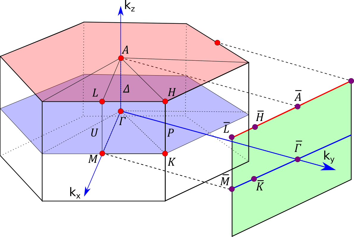
where the Pauli matrices operate in spin space. (See Fig. 1 for the definition of the coordinate system.) The screw rotations protect nodal points within rotation invariant lines, while the glide mirrors guarantee the stability of nodal lines within mirror invariant planes.
II.1 Weyl nodal points
Nodal points occur along the ––A and M–U–L lines of the hexagonal BZ, which are left invariant by the screw rotations and , respectively. Let us discuss these two cases separately. It should be noted that nodal points discussed in this section can in certain cases be part of Weyl nodal lines. An example of this is presented in Sec. IV.1.
II.1.1 M–U–L
The M–U–L line is defined as the segment , with , which connects the two time-reversal invariant momenta (TRIMs) M and L along the direction, see Fig. 1. This line segment is left invariant under the twofold rotation , up to a reciprocal lattice translation. Hence, the Bloch bands within this segment can be chosen to be simultaneous eigenstates of with eigenvalues
| (5) |
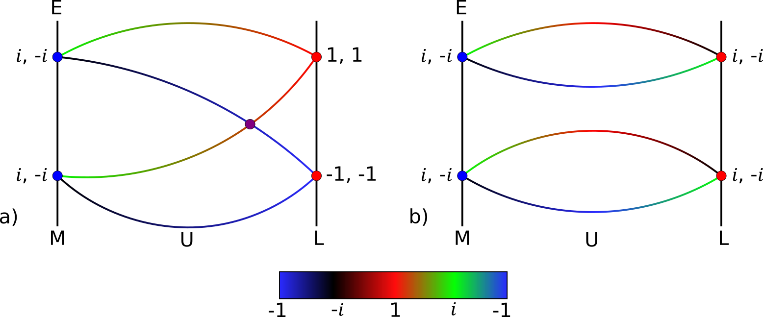
which follows from Eq. (2) with and . Due to the presence of spin-orbit coupling, the energy bands are in general non-degenerate, except at TRIMs (i.e., at M and L), where time-reversal symmetry enforces Kramers degeneracies. From Eq. (5), we find that at the M point has eigenvalues for all , while at the L point the eigenvalues are for even and for odd. At the M and L points time-reversal symmetry pairs up bands whose eigenvalues are complex conjugate pairs. Therefore, Kramers partners at the M point have opposite eigenvalues, while at the L point they have the same eigenvalues for odd and opposite eigenvalues for even. In the absence of additional symmetries, this leads to the band connectivity diagrams shown in Fig. 2. For odd, we see that there are four bands forming a connected group, which must cross at least once, leading to Weyl point degeneracies with an hourglass dispersion Alexandradinata et al. (2016). For even, on the other hand, only two bands form a connected group without any symmetry-enforced crossings.
From the above considerations, we expect that materials in SGs containing screw rotations with odd have band crossings along the M–U–L line. However, some of these SGs contain additional symmetries that lead to extra band degeneracies. In particular, mirror and inversion symmetries enforce extra degeneracies at the L point, between bands with eigenvalues and . Therefore, in the presence of additional mirror or inversion symmetries the band crossing along the M–U–L line is no longer symmetry-required. In conclusion, we find that only those materials with SGs containing a screw rotation with odd, but no inversion or mirror symmetry, exhibit the Weyl degeneracies within the M–U–L line. These are the SGs with Nos. 169, 170, 173, 178, 179, and 182, as indicated in the second column of Table 1.
II.1.2 ––A
| Pairings of | ||
|---|---|---|
| 0 | (0,5), (1,4), (2,3) | |
| 1 | (0,0), (3,3), (1,5), (2,4) | |
| 2 | (0,1), (2,5), (3,4) | |
| 3 | (1,1), (4,4), (0,2), (3,5) | |
| 4 | (0,3), (1,2), (4,5) | |
| 5 | (2,2), (5,5), (0,4), (1,3) |
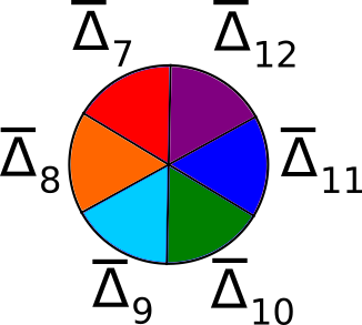
The path ––A is defined as the segment , with , which connects the point at the center of the BZ to the A point at the top surface of the BZ, see Fig. 1. Since this path is invariant under the sixfold screw rotation , we can label the Bloch states within ––A by the eigenvalues of , i.e.,
| (6) |
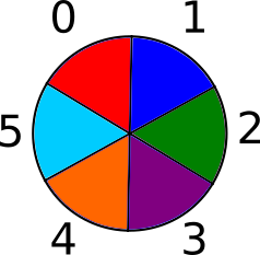
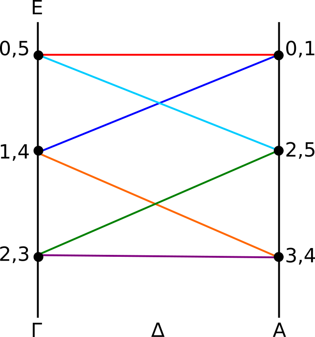
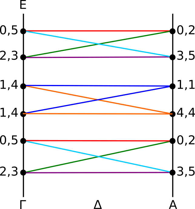
where the eigenvalue label runs from 0 to 5, cf. Eq. (2). Due to Kramers theorem, time-reversal symmetry enforces degeneracies at the TRIMs and A, between bands whose eigenvalues are complex conjugate pairs. Using Eq. (6), we find that at the point bands with the eigenvalue labels (0, 5), (1, 4), and (2, 3) form Kramers partners, independent of . At the A point, on the other hand, the way in which the bands pair up into Kramers partners depends on the value of , as specified in Table 2. We observe that for the bands pair up in different ways at the and A points. As a consequence, the Kramers pairs must switch partners between and A, which, in the absence of additional symmetries, leads to a nontrivial band connectivity. For and we find that there are twelve bands sticking together with an accordion-like dispersion, as shown in Fig. 3(a). These twelve bands have to cross at least five times, forming five Weyl point degeneracies. For and six bands stick together with a minimum number of two crossing points [Fig. 3(b)], while for four bands form at least one Weyl point degeneracy [Fig. 3(c)]. In general, one can show that for bands forming a connected group, the minimum number of crossings is . This is proven in Appendix A using mathematical induction. We note that the bands that cross at the Weyl points have different eigenvalues, which prevents hybridization between them. In addition, the Weyl points are protected by a nonzero Chern number, which gives rise to Fermi arcs at the surface, as will be demonstrated in Sec. IV.
From the above analysis, it follows that materials in SGs with screw rotations can have protected Weyl point degeneracies along the ––A line. However, some of these SGs contain in addition to also inversion or mirror symmetries, which create fourfould (or higher) degeneracies at the A point, thereby removing the symmetry-enforced Weyl crossings. Therefore, only materials in SGs with symmetries, but no mirror or inversion symmetry, display the discussed Weyl points at the ––A line. The SGs that satisfy these criteria are Nos. 169-173 and 178-182, as listed in Table. 1.
II.2 Weyl nodal lines
Nodal lines protected by glide mirror symmetries , Eq. (4), occur within mirror-invariant planes of the hexagonal BZ Wang et al. (2017). Within these planes, the Bloch bands can be chosen to be eigenstates of the glide mirror operator with eigenvalues
| (7) |
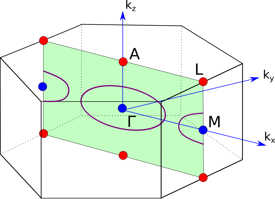
which follows from Eq. (2). Mirror invariant planes contain either two or four TRIMs at which the Bloch bands are Kramers degenerate, see blue and red dots in Fig. 4. It follows from Eq. (7) that at the A and L points the eigenvalues are and , while at the and M points they are and . At and M time-reversal symmetry enforces Kramers degeneracies between pairs with opposite eigenvalues (blue dots), while at A and L Kramers pairs are formed between bands with the same eigenvalues (red dots). This leads to a similar band connectivity as in Sec. II.1.1, cf. Fig. 2. That is, along any one-dimensional path within a mirror invariant plane, connecting /M to A/L, there must be at least one band crossing. Therefore, the mirror invariant planes must contain Weyl line degeneracies, as shown in Fig. 4. The shape of these nodal line crossings is restricted by time-reversal symmetry, which requires that each nodal line consists of pairs of Bloch states that are related by time-reversal symmetry. Due to these requirements each nodal line must enclose one or two TRIMs within the mirror plane.
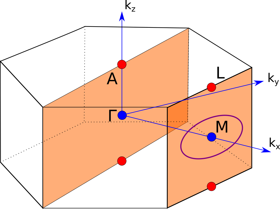
The discussed nodal lines only occur if there are no extra degeneracies at the TRIMs due to additional symmetries. We find that the screw rotations or inversion lead to extra degeneracies at the L and A points between bands with eigenvalues and . Hence, in the presence of these symmetries the L and M points become fourfold degenerate, such that the line crossings are no longer enforced by symmetry. Therefore only materials in SGs with glide mirror symmetries, but no inversion or symmetry, exhibit the predicted line crossings. The only SGs that satisfy these criteria are Nos. 188 and 190 111For SG Nos. 184, 185, and 186 the bands with eigenvalues and at the A and L points are forced to be degenerate by extra mirror symmetries. Therefore, there is no symmetry-enforced crossing in SG Nos. 184, 185, and 186, even though they have a suitable glide plane as pointed out in Ref. BzduÅ!’ek et al. (2016).. SG No. 188 () contains a glide mirror symmetry which leaves the -plane invariant, see Fig. 4(a). This plane contains four TRIMs: two where the Kramers partners have the same eigenvalues (red dots); and two where they have opposite eigenvalues (blue dots). Using the above arguments, we find that there must exist nodal lines within the -plane, which enclose two of the four TRIMs, as shown in Fig. 4(a). The mirror glide symmetry in SG 190 (), on the other hand, leaves two planes invariant, namely the and planes, see Fig. 4(b). Both of these mirror planes contain two TRIMs: one where the two Kramers partners have the same eigenvalues (red dots); and one where they have opposite eigenvalues (blue dots). From our analysis it follows that both mirror planes should contain at least one nodal loop, which either enclose the /M or A/L points. However, in SG No. 190 there exist four-dimensional irreducible representations at the A point, which makes the bands fourfold degenerate. Thus, symmetry-enforced nodal loops generically occur only within the plane, but not within the plane.
II.3 Compatibility relations between irreps
The symmetry enforced band crossings discussed in the previous two sections can also be derived from the compatibility relations between irreducible representations (irreps) at different high-symmetry points (or lines) of the BZ Kruthoff et al. (2017); Elcoro et al. (2017). Here, we give a brief outline of this derivation focusing on SG 171 (), further details can be found in Appendix B.
The symmetries of electronic band structures with spin-orbit coupling and time-reversal symmetry are described by double crystallographic SGs and their double-valued irreducible representations Bradley and Cracknell (1972); Elcoro et al. (2017). If we restrict the total band structure to a particular high-symmetry point (or high-symmetry line) in the BZ, then the symmetries of the band structure are reduced to a subgroup of the double SG, which is called the little group at . Since the Hamiltonian restricted to commutes with the corresponding little group, we can label its Bloch bands by the double valued irreps of the little group. Moving in a continuous way from a point with high symmetry (, say) to a point with lower symmetry (, say), we find that the little-group irreps at these two points must be related to each other, as the little groups at and form a group-subgroup pair. In fact, a representation of the little group at can be subduced from the little-group irreps at . By decomposing this subduced representation into irreps, one obtains the compatibility relations between the irreps at and Miller and Love (1967); Elcoro et al. (2017). These compatibility relations then determine the connectivity of the Bloch bands in the BZ.
| Irrep\Element | E | |||||
|---|---|---|---|---|---|---|
| 1 | -i | -1 | i | 1 | -i | |
| 1 | i | -1 | -i | 1 | i | |
| 1 | i | |||||
| 1 | -i | |||||
| 1 | i | |||||
| 1 | -i |
| Irrep\Element | E | |||||
| 1 | -i | |||||
| 1 | i | |||||
| 1 | -i | |||||
| 1 | i | |||||
| 1 | i | -1 | -i | 1 | i | |
| 1 | -i | -1 | i | 1 | -i |
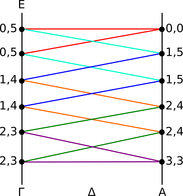
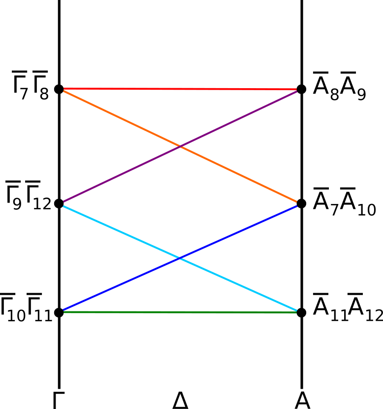
We will now show how this works for the case of SG 171 (). For this SG the relevant high-symmetry points that we need to consider are the TRIMs and A. These two TRIMs are connected by the high-symmetry line ––A, which is left invariant under the screw rotation (cf. Sec. II.1.2). To determine the connectivity of the bands between the and A points, we first derive the little-group irreps at , A, and ––A, and then study the compatibilities between them. Table 3 lists the calculated double-valued irreps at and A for SG 171 without time-reversal. In order to construct time-reversal symmetric irreps we pair complex conjugated irreps from Table 3 and form a direct sum out of them Bradley and Cracknell (1972); Elcoro et al. (2017). In this way we obtain at the point the real irreps , , and , while at the A point we get , , and . Note that these real irreps are all two-dimensional, leading to a twofold degeneracy of the bands at and A, in agreement with Kramers theorem. On the ––A line, however, the symmetry is lower, as time-reversal is absent; only the screw rotation remains as a valid symmetry. As a consequence, the little-group irreps at ––A are in general complex, as shown in Table 4.
| Irrep\Element | E | |
|---|---|---|
| 1 | ||
| 1 | ||
| 1 | ||
| 1 | ||
| 1 | ||
| 1 |
Next, we derive the compatibility relations between the little-group irreps at , A and ––A. This can be achieved, in principle, by studying the subduction of the little-group irreps at (or A) onto the little group at ––A Miller and Love (1967). Here, however, we can use a simpler method, which makes use of the following relation between the characters 222The character of a group irrep associates to each group element the trace of the corresponding irrep matrix. of the little-group irreps
| (8) |
where is the character of the symmetry element for the real irrep and is the set of irreps that decomposes into. Eq. (8) essentially follows from the fact that the characters of each valid symmetry must be preserved, as we continuously move from (or A) to a point on the ––A line. Using Eq. (8) we find that the real irreps at must decompose into
| (9) |
while for the real irreps at A we have
| (10) |
These two sets of equations are the compatibility relations between the little-group irreps at , A, and ––A.
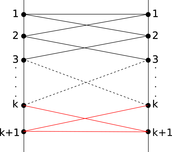
The Bloch bands along ––A must satisfy all of these compatibility relations. That is, as we move from to a point on ––A, Kramers pairs must decompose according to Eq. (II.3), while, as we approach A, they must pair up according to Eq. (II.3). As a consequence, the little-group irreps of ––A switch partners, as shown in Fig. 5. That is, the bands connect in a nontrivial way, with a minimum number of two crossings. This is in full agreement with Sec. II.1.2, cf. Fig. 3(b).
Using a similar approach as above, we have derived the compatibility relations for all SGs of Table 1 and constructed the corresponding band connectivity diagrams, see Appendix B. We find that the band connectivities obtained in this way fully agree with the derivation of Secs. II.1 and II.2. which is based on the algebraic relations obeyed by the symmetry operators.
II.4 Filling constraints
It follows from band theory that, in the presence of time-reversal symmetry, a noninteracting band insulator can form only if the electron filling is an even integer, i.e., 333The electron filling is defines as the number of electrons per primitive unit cells.. That is, materials without strong correlations and must necessarily be (semi-)metals. However, in materials with nonsymmorphic symmetries these filling constraints for the existence of band insulators are tightened Michel and Zak (2001); Young et al. (2012). I.e., nonsymmorphic symmetries forbid the existence of band insulators even when . This is because nonsymmorphic symmetries generally enforce extra band crossings, leading to groups of more than two connected bands, as we have seen in Secs. II.1 and II.2. Thus, we can use the analysis of the above two sections to derive tight filling constraints for the corresponding SGs. For example, for SG 169 we find that along the M–U–L line four bands form a connected group, while along the ––A line twelve bands form a connected group. Hence, for a material in SG 169 to be an insulator, these groups of bands must be fully filled, i.e., the electron filling must be an element of . Using similar arguments, tight filling constraints for all the SGs of Table 1 can be derived, see fifth column.
Recently, the tight filling constraints for all 230 SGs with time-reversal symmetry were calculated by Watanabe et al. Watanabe et al. (2016), using compatibility relations between irreducible representations. Our analysis is in full agreement with Ref. Watanabe et al. (2016) and, moreover, explicitly reveals both the nature and the topological protection of the enforced band crossings that lead to the tightened filling constraints.
III Band crossings protected by off-centered symmetries
Nonsymmorphic symmetries with a translation part that is perpendicular to the invariant space can be transformed into symmorphic symmetries by a suitable choice of reference for . For instance, a glide mirror symmetry with a translation part that is perpendicular to the mirror plane, can be transformed into a symmorphic mirror symmetry by shifting the origin by . However, in the presence of a second symmetry with a reference point different from , the two translation parts which are perpendicular to the point-group invariant spaces cannot be removed both at the same time, since a shift of the origin affects both and . A pair of two such symmetries are called “off-centered” symmetries Yang et al. (2017); Fang et al. (2015); Chiu et al. .
We are now going to show how these off-centered symmetries in hexagonal SGs lead to the protection of fourfold degenerate nodal lines (i.e., Dirac lines), which we refer to as type-(ii) nodal lines 444In certain SGs off-centered symmetries can also protect type-(ii) nodal points. This, however, is not the case for hexagonal materials with strong spin-orbit coupling.. The relevant off-centered symmetries that we need to consider for this purpose are: the glide mirror symmetry which transforms the spatial coordinates and the spin as
| (11) |
together with the inversion symmetry , which sends . Since , the eigenvalues of are . Within the two invariant planes, and , we can label the Bloch states , by the eigenvalues, i.e., . Applying the symmetry operators and successively, we obtain the following commutation relation
| (12) |
Thus, in the plane the two symmetry operators commute, while in the plane they anticommute. Now, since the time-reversal symmetry operator commutes with both and , anticommutes with within the plane. Hence, the Kramers pair and have the same eigenvalues for , since . Therefore, if two bands with opposite eigenvalues cross within the plane, they form a protected line crossing with fourfold degeneracy.
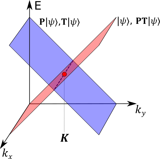
Such a fourfold degenerate nodal line is in fact required to exist by symmetry alone, i.e., it occurs in any material with the off-centered symmetries . To see this, let us consider the degeneracies at the two TRIMs A and L within the plane. At these TRIMs the Bloch states form quartets of four degenerate states with the eigenvalues
| (13) |
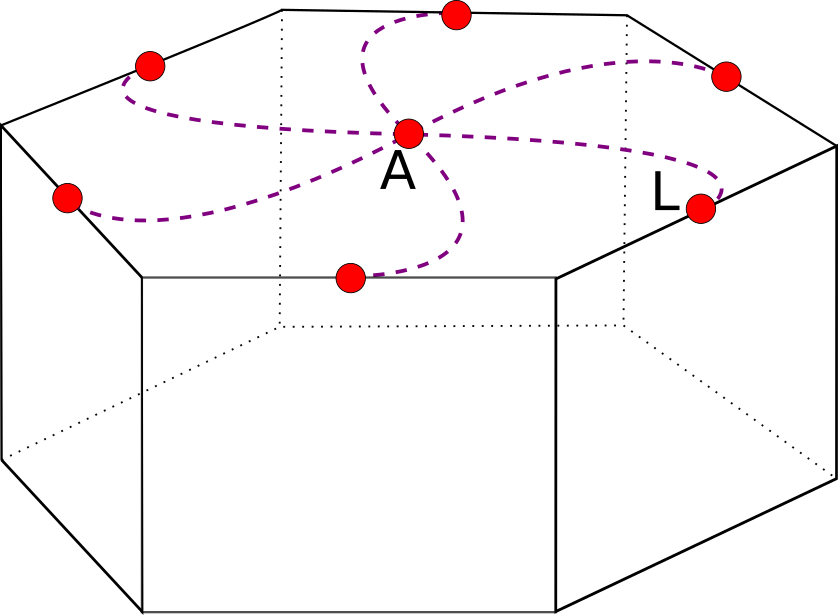
where . These four Bloch states are mutually orthogonal to each other, since they either have opposite eigenvalues or are Kramers partners. As we move away from the TRIMs, the Bloch bands become twofold degenerate in general. We find, however, that the two energetically degenerate states and , which are mapped onto each other by (or by ), have opposite eigenvalues. This leads to a band structure, whose eigenvalues are inverted with respect to , as shown in Fig. 6(a). Since the Bloch bands are smooth functions of , each quartet of Bloch states at must therefore be part of a fourfold degenerate nodal line connecting two TRIMs, as illustrated in Fig. 6(b). Note that this fourfold degenerate nodal line must be symmetric under and and all other point-group symmetries of the SG, but is otherwise free to move within the plane. For this reason, the type-(ii) nodal lines in hexagonal systems are typically shaped like a star [see Fig. 6(b)].
From the above analysis, we expect that hexagonal materials in SGs containing both inversion and the glide mirror symmetry (11) have protected type-(ii) nodal lines. The SGs that fulfill these criteria are Nos. 176, 193, and 194 (cf. Talbe 1). However, for SG Nos. 193 and 194 additional symmetries force the nodal lines to be pinned to the high-symmetry lines connecting A to L and A to H, respectively. Hence, in these cases the fourfold degeneracy is simply a consequence of the four dimensionality of the corresponding irreducible space-group representation, and hence the argument based on off-centered symmetries is not needed.
IV Example Materials
To find example materials, we look for compounds crystallizing in one of the 13 SGs of Table 1 with heavy elements, showing large spin-orbit coupling. For that purpose we perform an extensive search of the Inorganic Crystal Structure Database (ICSD) from FIZ Karslruhe ICS ; Curtarolo et al. (2012), focusing on binary compounds and simple ternary compounds. This search yields two materials with nodal points and two materials with nodal lines, which we are now going to discuss in detail.
For the four example materials we perform DFT calculations with the Vienna ab initio simulation package (VASP) Kresse and Furthmüller (1996a, b) using the projector augmented wave (PAW) method Blöchl (1994); Kresse and Joubert (1999) and the PBE functional Perdew et al. (1996) for the exchange-correlation energy. As input for the DFT calculations the experimental crystal structure of Refs. Zemva et al. (1991); Likforman et al. (1980); Zumdick and P ttgen (1999); Kr mer et al. (1989) was used. In the main text we present only those features of the band structures that clearly show the predicted band crossings, while the full band structures are shown in Appendix C. For one of the four materials, we also compute the surface states using a Wannier-based tight-binding model Mostofi et al. (2008) and an iterative Green s function method Sancho et al. (1985).
IV.1 Materials with nodal points
AuF3—
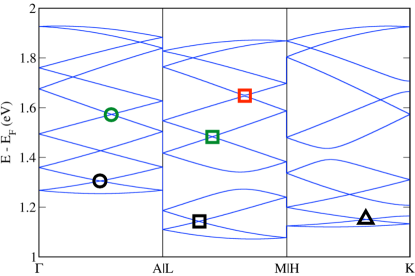
Gold trifluoride AuF3 Zemva et al. (1991) crystallizing in SG (No. 178) is an example of a hexagonal material with Weyl point nodes along the ––A and M–U–L lines (cf. Sec. II.1). The first-principles band structure of AuF3 displays a well separated group of twelve bands 1.5 eV above the Fermi energy . [Figs. 7 and A2(a)]. This group of bands shows the predicted Weyl points in a very clear way. Along the ––A line, which is symmetric under the screw rotation , we observe a group of twelve bands sticking together with an accordion-like dispersion, forming five crossings. Along the M–U–L line, which is invariant under the screw rotation , there are groups of four connected bands, with an hourglass dispersion and a single crossing point. (Note that the two bands marked by the red square form an avoided crossing.) This is in complete agreement with the theoretical band connectivity diagrams of Figs. 3(a) and 2(a), respectively. The occupied states below the Fermi level (see Fig. A2(a) in Appendix C) exhibit the same band connectivity as the unoccupied ones in Fig. 7. That is, along the ––A and M–U–L lines, there are groups of 12 and 4 connected bands, respectively, which form a large number of Weyl points (and possibly also Weyl lines) protected by the screw rotation symmetries.
The topological stability of all these Weyl points is ensured by quantized Chern numbers, which endow the Weyl points with definite chiralities . Interestingly, the chiralities of the Weyl points of AuF3 can be infered from symmetry alone, at least up to some overall signs. This can be achieved using the following three observations. First, the chiralities must be either or , since all the bands cross linearly and not quadratically Huang et al. (2016). Second, the chiralities of all the Weyl points formed by one pair of bands must add up to zero, due to the fermion doubling theorem Nielsen and Ninomiya (1981). Third, Weyl points which are mapped onto each other under space group symmetries must have the same charilities. Using these three observations, let us, as an example, analyze the chiralities of the Weyl points formed by the second and third lowest bands in Fig. 7 (black open symbols). How the bands connect across the entire BZ can be deduced from Fig. A2 shown in Appendix C. Looking at the hexagonal BZ in Fig. 1, we see that there are three Weyl points at the M–U–L lines with chirality , two Weyl points at the K–P–H lines with chirality , and one Weyl point at the ––A line with chirality . Hence, the chiralities of these six Weyl points must obey the equation , which, up to an overall sign, fully determines the chiralites, i.e., 555It should be noted that the second and third lowest conduction bands can, in principle, also form accidental Weyl points, i.e., Weyls points aways from high-symmetry lines, whose existence is not enforced by symmetry. These accidential Weyl points always come in opposite chirality pairs, such that their contribution to the equation for the chiralities cancels out. . Similar arguments can be made for all the other Weyl points of AuF3 and in fact for any material with these type-(i) Weyl points (cf. Table 1). A peculiar case are the crossings formed by the sixth and seventh lowest bands in Fig. 7 (green open symbols). We find that these bands cross only on the ––A and M–U–L lines, but not along the K–P–H path. Therefore, the chiralities must satisfy , which paradoxically has no solution. The resolution to this conundrum, is that the band crossings marked by the green symbols are not actually Weyl points, but rather Weyl nodal lines, whose chirality is illdefined. These Weyl nodal lines connect the M–U–L path to the ––A path in a sixfold star-shaped pattern, which is confirmed by our ab-initio DFT calculations (not shown).
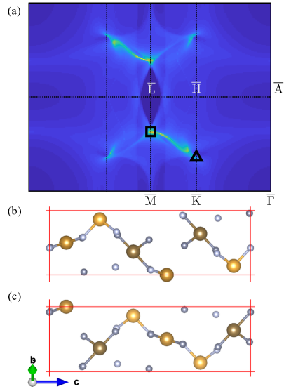
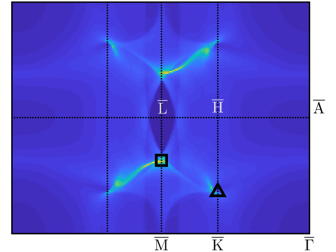
The nontrivial topology exhibited by the Weyl points of AuF3 manifests itself at the surface through arc states, which connect Weyl points with opposite chiralities. This is shown in Fig. 8, which displays the surface density of states of a semi-infinite AuF3 slab with (010) face at the energy eV. The corresponding surface BZ is shown on the right of Fig. 1. The crystal structure of AuF3 allows for two different (010) terminations, which are displayed in Figs. 8(b) and 8(c). In Fig. 8(a) we show the surface density of states for the bottom termination; the corresponding plot for the top termination is presented in Fig. A3 of Appendix C. We observe that there are two arc states connecting the projected Weyl points of the M–U–L and K–P–H lines, which are marked by the black square and triangle, respectively. Similar arc states occur for all the other Weyl points along the ––A and M–U–L lines, also in the occupied bands.
While the band connectivity and the associated Weyl points of AuF3 are very interesting from a theoretical point of view, this material is rather difficult to handle experimentally, as it is highly reactive. Moreover, AuF3 is insulating with a large band gap of eV, which makes it nearly impossible to probe the bulk Weyl points and arc surface states using tunneling spectroscopy, photoemission, or transport experiments. Therefore, in order to experimentally confirm the predicted band crossings, it is more feasible to instead consider the phase of In2Se3.
In2Se3—
In2Se3 exists in several polymorphic forms Ji et al. (2013). In one of them, the so called phase, In2Se3 crystallizes in the space group (169) Likforman et al. (1980). Hence, according to our classification Table 1, the band structure of -In2Se3 exhibits Weyl points along the ––A and M–U–L lines, which are protected by the screw rotations and , respectively. Fig. 9 displays the ab initio band structure of -In2Se3, which clearly shows these Weyl points. We observe groups of four connected bands along the M–U–L direction, which cross at least once, similar to the band connectivity diagram 2(a). Along the ––A line there are groups of 12 connected bands, which form at least Weyl points [Fig. 9 and A2(b)]. Similar to AuF3, these Weyl points lead to arc surface states, due to the bulk boundary correspondence. Here, however, the arc states are much closer to the Fermi energy, which makes it possible to observe them using, e.g., angle-resolved photoemission or scanning tunneling spectroscopy. Moreover, -In2Se3 can have p-type defects that would move the Fermi level closer to the Weyl points. This would allow to measure the topological transport signatures of the Weyl points, e.g., anomalous (magneto-)transport properties due to the chiral anomaly Armitage et al. (2017); Burkov (2018a). In addition, -In2Se3 is expected to exhibit large anomalous Hall effects, since all the bands carry a non-zero Berry curvature, which is especially large close to the Weyl points.
IV.2 Materials with nodal lines
Here, we present two materials with symmetry enforced nodal lines: ZrIrSn, which has twofold degenerate Weyl nodal lines [type-(i)] and LaBr3, which exhibits fourfold degenerate Dirac nodal lines [type-(ii)].
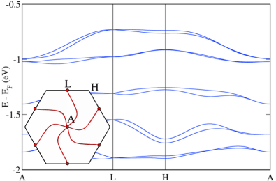
ZrIrSn—
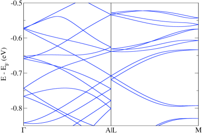
ZrIrSn crystallizing in SG (No. 190) Zumdick and P ttgen (1999) is an example of a hexagonal material with Weyl nodal lines protected by a mirror glide symmetry. In Fig. 10 we present the first-principles band structure of ZrIrSn. Along the M–U–L line, which is invariant under the mirror glide symmetry , we observe groups of four connected bands, which cross each other at least once. Since these crossings must occur for any path within the plane connecting M to L (cf. Sec. II.2), they form Weyl nodal lines. The shape of the Weyl nodal line for the crossing near eV is shown in the inset of Fig. 10. All the other Weyl nodal lines have similar shapes and enclose one of the TRIMs M or L in the plane. We emphasize that all the bands within the plane form such Weyl nodal lines, since their existence is enforced by the mirror glide symmetry. The topological properties of these Weyl nodal lines are characterized by a nonzero Berry phase Chan et al. (2016), which, by the bulk-boundary correspondence, leads to drumhead states at the surface of ZrIrSn. Moreover, due to the absence of inversion, the bands in ZrIrSn carry a nonzero Berry curvature, which is particularly large close to the Weyl nodal lines. In slightly doped samples of ZrIrSn this should give rise to anomalous transport properties, such as, e.g., large anomalous Hall effects or anomalous magnetoelectric responses BzduÅ!’ek et al. (2016).
LaBr3—
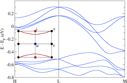
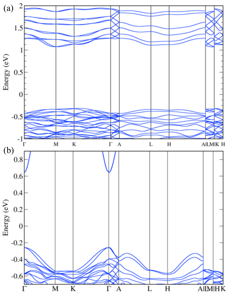
An example of a hexagonal material with Dirac nodal lines is LaBr3 in SG (No. 176) Kr mer et al. (1989). As indicated in Table 1, materials in this SG exhibit fourfold degenerate nodal lines within the plane protected by the off-centered symmetries and . In order to verify this, we perform first-principles band structure calculations of LaBr3 to obtain the band structure shown in Figs. 11 and A4(c). All the bands of LaBr3 are Kramers degenerate, since SG No. 176 () contains a symmetry which squares to . Along the A–L–H–A path, within the plane, there are groups of two Kramers degenerate bands which cross each other several times. These band crossings are part of a fourfold degenerate Dirac nodal line, whose shape resembles a star (inset of Fig. 11), in complete agreement with the theoretical analysis of Sec. III. These Dirac nodal lines are protected from hybridizing, since the bands that cross have opposite eigenvalues. Note that such star-shaped Dirac nodal lines are formed by all the bands at all energies, since their existence follows from symmetry alone, independent of the energetics of the bands. Thus, probing this insulating material below the Fermi energy (which might be possible if flakes of this layered compound are deposited on a metallic substrate) with ARPES, would reveal the star shaped band crossings.
In closing we note that LiScI3 Lachgar et al. (1991) crystallizing in SG (No. 188) is an example of a material with Weyl nodal lines within the -plane. Unfortunately, the spin-orbit coupling in this material is rather weak, leading to a band splitting of only about meV. We therefore do not discuss this material in any further detail here.
V Conclusions
In this work we have classified all possible nonsymmorphic band degeneracies in hexagonal materials with time-reversal symmetry and strong spin-orbit coupling. Our classification approach is based on representation theory of space groups and the algebraic relations between symmetry operators. We find that thirteen out of the 27 hexagonal space groups (SGs) support topological band crossings protected by nonsymmorphic symmetries (Table 1). Among them there are ten SGs with Weyl nodal points (Nos. 169-173 and Nos. 178-182), two SGs with Weyl nodal lines (Nos. 188 and 190) and one SG with Dirac nodal lines (No. 176). The stability of these band crossings is ensured by quantized topological numbers, i.e., by a Chern number or a -Berry phase. We emphasize that the appearance of these band crossings is enforced by symmetry alone, i.e., they occur in any (weakly correlated) material crystallizing in these SGs, regardless of the chemical composition.
The results of our classification are helpful for searching and designing materials with Weyl and Dirac nodal points or nodal lines. Using the Inorganic Crystal Structure Database (ICSD) ICS , we have identified a number of hexagonal materials which exhibit topological band crossings (last column of Table 1). Particularly interesting are -In2Se3 and ZrIrSn, as their band crossings are sufficiently close to the Fermi energy to be measurable. The nontrivial topology of the band crossings in these two materials has various experimental consequences: arc and drumhead surface states, which can be observed by angle-resolved photoemission, and various anomalous responses to external probes, such as anomalous magnetotransport properties, and anomalous Hall effects Burkov (2018a). These anomalous properties may open up the possibilities for new device applications, such as spin-filter transistors Shi et al. (2015), or valleytronics applications, which utilize the valley degree of freedom to process information Schaibley et al. (2016); Rui et al. (2017). We hope that this will stimulate experimentalists to synthesize the reported materials and study their topological properties and responses.
In closing, we mention several interesting directions for future studies. First, our approach can be generalized to other magnetic and nonmagnetic SGs containing screw rotations or glide mirror symmetries. In particular, materials in SGs containing threefold or fourfold screw rotations (e.g., in trigonal systems Tri ) can have multiple Weyl band crossings with accordion-like dispersions, similar to Fig. 3. Second, it would be of interest to derive a detailed theory of the topological responses, in particular for the Dirac nodal line materials in SG No. 176, which remain poorly understood. Third, we expect that our analysis can be adapted to bosonic systems, for example, phononic or photonic band structures, or the bands formed by elementary excitations of quantum magnets.
Acknowledgements.
The authors thank M. Hirschmann and A. Yaresko for useful discussions. This research was partially supported by NSF through the Princeton Center for Complex Materials, a Materials Research Science and Engineering Center DMR-1420541. M.G.V. was supported by IS2016-75862-P national project of the Spanish MINECO. C.-K.C. acknowledges support by Microsoft and the Laboratory for Physical Science. J.Z. thanks the Max-Planck-UBC-Tokyo Centre for Quantum Materials for hospitality and financial support.Appendix A Minimum number of crossings

In this appendix we prove that bands forming a connected group along a line in between two TRIMs must cross at least times (cf. Sec. II.1). This problem is closely related to finding the minimum number of crossings for a bipartite graph, which in general is not a solved problem Tamassia (2013). However, in the case of connected groups of bands with time-reversal symmetry and spin-orbit coupling, the corresponding bipartite graphs exhibit additional constraints, such that a proof can be constructed using mathematical induction.
We start by relating connected groups of bands to connected bipartite graphs of order . For that purpose, we identify the energy values of the Kramer’s pairs at the two TRIMs with the vertices (i.e., nodes) of the graph. The edges (i.e., lines) of the graph are identified with the bands along the path that connects the two TRIMs. Because this identification is one-to-one, the lines cannot curve outside the nodes to avoid crossings. Each node of the graph has degree two, because in the absence of inversion symmetry the Kramer’s pairs split into two nondegenerate bands as we move away from the TRIMs. Moreover, the graph is bipartite, since every line connects two nodes of two distinct TRIMs. The order of the graph is , because bands form Kramer’s pairs at the two TRIMs. Using mathematical induction, we will now show that the minimum number of crossings in this bipartite graph with nodes is .
First we need to proof this statement for : The minimum number of crossings in a bipartite graph with two nodes is trivially zero, since a double connection between two nodes never has to cross itself. For the induction step, we need to show that if the statement holds for a graph with nodes, it must also hold for a graph with nodes. So let us assume that there is a graph with nodes with crossing number . We now wish to connect two more nodes of degree two to the bipartite graph, (i.e, one node at each TRIM), such that the total number of crossings is increased by as little as possible (see Fig. A1). This is achieved by (i) connecting the th node at the left TRIM to the th node at the right TRIM and (ii) connecting the th node at the left TRIM to the th node at the right TRIM, and vice versa. This creates one additional crossing. Thus, the total number of crossings is now , which completes the proof.
Appendix B Representation theory
To be completed.
Appendix C Additional band structure and surface state calculations
In this appendix we present additional band structure and surface state calculations for the example materials discussed in the main text.
Figure A2 displays the full band structures of the two materials AuF3 and -In2Se3, which exhibit Weyl points. AuF3 is insulating with a large gap of eV. We observe that Weyl points with accordion dispersions occur along ––A both in the conduction and valence bands. While the accordion dispersion is clearly visible above , it is less clear below , where the bands are not well separated in energy [Fig. A2(a)]. Nevertheless, all valence bands form Weyl points along the ––A and M–U–L lines, as required by symmetry. By the bulk-boundary correspondence these Weyl points give rise to arc surface states. Figure A3 shows the arc states at the (010) surface of AuF3 with top termination, which connect the Weyl points formed by the lowest two conduction bands. Since AuF3 is insulating with a gap of eV, it is very difficult to experimentally probe the Weyl points. In principle, one could try to dope AuF3 with F defects to bring the Fermi level into the valence band. But this is likely challenging.
The phase of In2Se3 is also insulating, but with a smaller gap of eV, see Fig. A2(b). Here, it might be possible to measure the Weyl points along the ––A line using photoemission, as they are only about 300-400 meV below the Fermi energy. It might also be possible to observe signatures of the Fermi arc states using Fourier-transform scanning tunneling spectroscopy.
In Fig. A4 we present the full band structures of the nodal line materials ZrIrSn and LaBr3, which exhibit Weyl and Dirac nodal lines, respectively. ZrIrSn contains two Weyl nodal lines within the plane that are only about 100 meV away from the Fermi energy (Figs. A4(a) and 10). These Weyl nodal lines give rise to drumhead states on the (100) and (010) surfaces. Because of spin-orbit coupling, these drumhead surface states posses an intricate helical spin texture, with the spin and momentum directions locked to each other. It should be possible to measure this spin texture using, e.g., spin-resolved photoemission or spin-resolved scanning tunneling spectroscopy. Furthermore, in slightly doped ZrIrSn samples the Weyl nodal lines could be accessed in transport experiments. We expect that this material will show anomalous magnetoelectric responses and anomalous Hall effects, since the bands carry a nonzero Berry curvature.
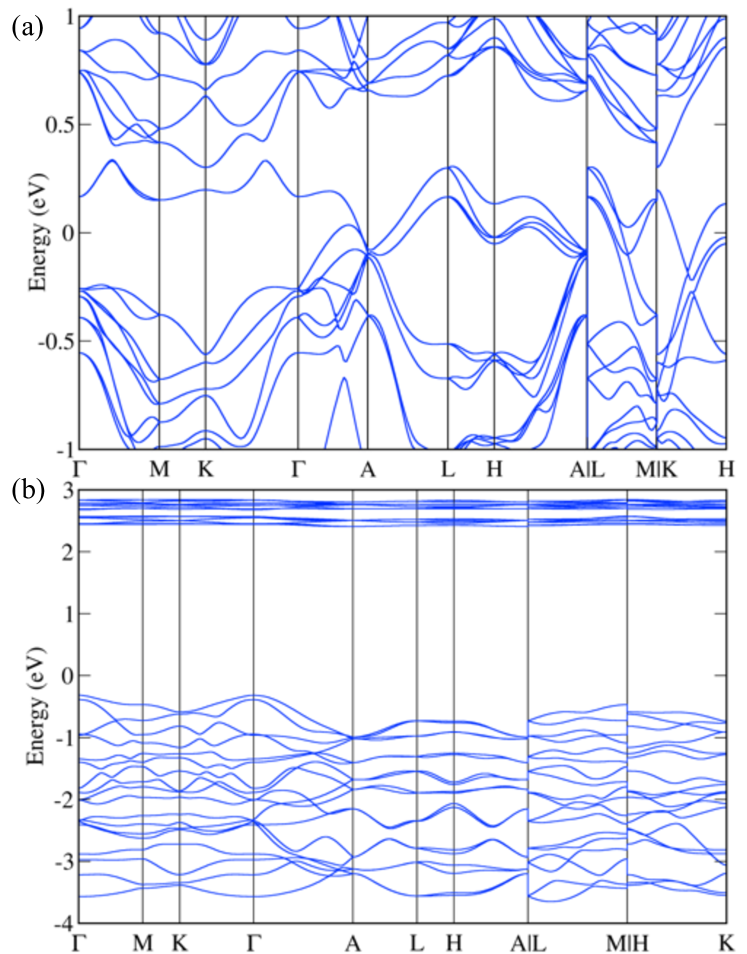
The Dirac nodal lines of LaBr3, which are located within the plane, are difficult to observe, as this material is insulating with a gap of about eV [Fig. A4(b)]. It might be possible to probe the Dirac nodal lines below the Fermi energy in exfoliated flakes of LaBr3 deposited on a metallic substrate. However, this is likely challenging as the material is air sensitive. Therefore, the search for suitable Dirac nodal-line materials in SG 176 with band crossing at the Fermi energy remains as a goal for future work.
References
- Chiu et al. (2016) C.-K. Chiu, J. C. Y. Teo, A. P. Schnyder, and S. Ryu, Rev. Mod. Phys. 88, 035005 (2016).
- Volovik (2013) G. E. Volovik, Topology of quantum vacuum, Lecture Notes in Physics, Vol. 870 (Springer Berlin, 2013) pp. 343–383.
- Armitage et al. (2017) N. P. Armitage, E. J. Mele, and A. Vishwanath, ArXiv e-prints (2017), arXiv:1705.01111 [cond-mat.str-el] .
- Burkov (2018a) A. Burkov, Annual Review of Condensed Matter Physics 9, null (2018a), https://doi.org/10.1146/annurev-conmatphys-033117-054129 .
- Yang et al. (2017) S.-Y. Yang, H. Yang, E. Derunova, S. S. P. Parkin, B. Yan, and M. N. Ali, ArXiv e-prints (2017), arXiv:1707.04523 [cond-mat.mtrl-sci] .
- Wan et al. (2011) X. Wan, A. M. Turner, A. Vishwanath, and S. Y. Savrasov, Phys. Rev. B 83, 205101 (2011).
- Burkov et al. (2011) A. A. Burkov, M. D. Hook, and L. Balents, Phys. Rev. B 84, 235126 (2011).
- Lv et al. (2015) B. Q. Lv, H. M. Weng, B. B. Fu, X. P. Wang, H. Miao, J. Ma, P. Richard, X. C. Huang, L. X. Zhao, G. F. Chen, Z. Fang, X. Dai, T. Qian, and H. Ding, Phys. Rev. X 5, 031013 (2015).
- Young et al. (2012) S. M. Young, S. Zaheer, J. C. Y. Teo, C. L. Kane, E. J. Mele, and A. M. Rappe, Phys. Rev. Lett. 108, 140405 (2012).
- Wang et al. (2012) Z. Wang, Y. Sun, X.-Q. Chen, C. Franchini, G. Xu, H. Weng, X. Dai, and Z. Fang, Phys. Rev. B 85, 195320 (2012).
- Wang et al. (2013) Z. Wang, H. Weng, Q. Wu, X. Dai, and Z. Fang, Phys. Rev. B 88, 125427 (2013).
- Xie et al. (2015) L. S. Xie, L. M. Schoop, E. M. Seibel, Q. D. Gibson, W. Xie, and R. J. Cava, APL Mater. 3, 083602 (2015), http://dx.doi.org/10.1063/1.4926545.
- Chan et al. (2016) Y.-H. Chan, C.-K. Chiu, M. Y. Chou, and A. P. Schnyder, Phys. Rev. B 93, 205132 (2016).
- Yamakage et al. (2016) A. Yamakage, Y. Yamakawa, Y. Tanaka, and Y. Okamoto, Journal of the Physical Society of Japan 85, 013708 (2016), http://dx.doi.org/10.7566/JPSJ.85.013708 .
- Heikkilä and Volovik (2011) T. T. Heikkilä and G. E. Volovik, JETP Letters 93, 59 (2011).
- Schoop et al. (2016) L. M. Schoop, M. N. Ali, C. StraÃ?er, A. Topp, A. Varykhalov, D. Marchenko, V. Duppel, S. S. P. Parkin, B. V. Lotsch, and C. R. Ast, Nature Communications 7 (2016).
- Hořava (2005) P. Hořava, Phys. Rev. Lett. 95, 016405 (2005).
- Shiozaki and Sato (2014) K. Shiozaki and M. Sato, Phys. Rev. B 90, 165114 (2014).
- Zhao et al. (2016) Y. X. Zhao, A. P. Schnyder, and Z. D. Wang, Phys. Rev. Lett. 116, 156402 (2016).
- Zhao and Wang (2013) Y. X. Zhao and Z. D. Wang, Phys. Rev. Lett. 110, 240404 (2013).
- Chiu and Schnyder (2014) C.-K. Chiu and A. P. Schnyder, Phys. Rev. B 90, 205136 (2014).
- Po et al. (2017) H. C. Po, A. Vishwanath, and H. Watanabe, Nature Communications 8 (2017).
- Khalaf et al. (2017) E. Khalaf, H. C. Po, A. Vishwanath, and H. Watanabe, ArXiv e-prints (2017), arXiv:1711.11589 [cond-mat.str-el] .
- Song et al. (2017) Z. Song, T. Zhang, Z. Fang, and C. Fang, ArXiv e-prints (2017), arXiv:1711.11049 [cond-mat.mes-hall] .
- Fang et al. (2017) C. Fang, Z. Song, and T. Zhang, ArXiv e-prints (2017), arXiv:1711.11050 [cond-mat.mes-hall] .
- Bradlyn et al. (2017) B. Bradlyn, L. Elcoro, J. Cano, M. G. Vergniory, Z. Wang, C. Felser, M. I. Aroyo, and B. A. Bernevig, Nature 547, 298 (2017).
- Michel and Zak (2001) L. Michel and J. Zak, Physics Reports 341, 377 (2001), symmetry, invariants, topology.
- Bradley and Cracknell (1972) C. Bradley and A. P. Cracknell, The Mathematical Theory of Symmetry in Solids: Representation theory for point groups and space groups (Clarendon Press, 1972).
- Vergniory et al. (2017) M. G. Vergniory, L. Elcoro, Z. Wang, J. Cano, C. Felser, M. I. Aroyo, B. A. Bernevig, and B. Bradlyn, Phys. Rev. E 96, 023310 (2017).
- Chen et al. (2017) R. Chen, H. C. Po, J. B. Neaton, and A. Vishwanath, Nature Physics 14 (2017).
- Bradlyn et al. (2016) B. Bradlyn, J. Cano, Z. Wang, M. G. Vergniory, C. Felser, R. J. Cava, and B. A. Bernevig, Science (2016), 10.1126/science.aaf5037, http://science.sciencemag.org/content/early/2016/07/20/science.aaf5037.full.pdf .
- Freed and Moore (2013) D. S. Freed and G. W. Moore, Annales Henri Poincaré 14, 1927 (2013).
- Michel and Zak (1999) L. Michel and J. Zak, Phys. Rev. B 59, 5998 (1999).
- Zhao and Schnyder (2016) Y. X. Zhao and A. P. Schnyder, Phys. Rev. B 94, 195109 (2016).
- Young and Kane (2015) S. M. Young and C. L. Kane, Phys. Rev. Lett. 115, 126803 (2015).
- Alexandradinata et al. (2016) A. Alexandradinata, Z. Wang, and B. A. Bernevig, Phys. Rev. X 6, 021008 (2016).
- BzduÅ!’ek et al. (2016) T. BzduÅ!’ek, Q. Wu, A. Rüegg, M. Sigrist, and A. A. Soluyanov, Nature 538, 75 (2016).
- Furusaki (2017) A. Furusaki, Science Bulletin 62, 788 (2017).
- Takahashi et al. (2017) R. Takahashi, M. Hirayama, and S. Murakami, Phys. Rev. B 96, 155206 (2017).
- Yang et al. (2017) B.-J. Yang, T. A. Bojesen, T. Morimoto, and A. Furusaki, Phys. Rev. B 95, 075135 (2017).
- Fang et al. (2015) C. Fang, Y. Chen, H.-Y. Kee, and L. Fu, Phys. Rev. B 92, 081201 (2015).
- Mañes (2012) J. L. Mañes, Phys. Rev. B 85, 155118 (2012).
- (43) C.-K. Chiu, Y.-H. Chan, and A. P. Schnyder, to be published .
- Ando (2013) Y. Ando, Journal of the Physical Society of Japan 82, 102001 (2013), https://doi.org/10.7566/JPSJ.82.102001 .
- Burkov (2018b) A. A. Burkov, Phys. Rev. Lett. 120, 016603 (2018b).
- Burkov (2018) A. A. Burkov, ArXiv e-prints (2018), arXiv:1802.00450 [cond-mat.mes-hall] .
- Rui et al. (2017) W. B. Rui, Y. X. Zhao, and A. P. Schnyder, ArXiv e-prints (2017), arXiv:1703.05958 [cond-mat.mes-hall] .
- (48) Https://icsd.fiz-karlsruhe.de/.
- Dresselhaus et al. (2008) M. S. Dresselhaus, G. Dresselhaus, and A. Jorio, Group Theory, Application to the Physics of Condensed Matter (Springer Verlag, Berlin Heidelberg, 2008).
- Wang et al. (2017) L. Wang, S.-K. Jian, and H. Yao, Phys. Rev. B 96, 075110 (2017).
- Note (1) For SG Nos. 184, 185, and 186 the bands with eigenvalues and at the A and L points are forced to be degenerate by extra mirror symmetries. Therefore, there is no symmetry-enforced crossing in SG Nos. 184, 185, and 186, even though they have a suitable glide plane as pointed out in Ref. BzduÅ!’ek et al. (2016).
- Kruthoff et al. (2017) J. Kruthoff, J. de Boer, J. van Wezel, C. L. Kane, and R.-J. Slager, Phys. Rev. X 7, 041069 (2017).
- Elcoro et al. (2017) L. Elcoro, B. Bradlyn, Z. Wang, M. G. Vergniory, J. Cano, C. Felser, B. A. Bernevig, D. Orobengoa, G. de la Flor, and M. I. Aroyo, Journal of Applied Crystallography 50, 1457 (2017).
- Miller and Love (1967) S. C. Miller and W. F. Love, Tables of Irreducible Representations of Space Groups and Co-representations of Magnetic Groups (Boulder: Pruett, 1967).
- Note (2) The character of a group irrep associates to each group element the trace of the corresponding irrep matrix.
- Note (3) The electron filling is defines as the number of electrons per primitive unit cells.
- Watanabe et al. (2016) H. Watanabe, H. C. Po, M. P. Zaletel, and A. Vishwanath, Phys. Rev. Lett. 117, 096404 (2016).
- Note (4) In certain SGs off-centered symmetries can also protect type-(ii) nodal points. This, however, is not the case for hexagonal materials with strong spin-orbit coupling.
- Curtarolo et al. (2012) S. Curtarolo, W. Setyawan, S. Wang, J. Xue, K. Yang, R. H. Taylor, L. J. Nelson, G. L. Hart, S. Sanvito, M. Buongiorno-Nardelli, N. Mingo, and O. Levy, Computational Materials Science 58, 227 (2012).
- Kresse and Furthmüller (1996a) G. Kresse and J. Furthmüller, Phys. Rev. B 54, 11169 (1996a).
- Kresse and Furthmüller (1996b) G. Kresse and J. Furthmüller, Computational Materials Science 6, 15 (1996b).
- Blöchl (1994) P. E. Blöchl, Phys. Rev. B 50, 17953 (1994).
- Kresse and Joubert (1999) G. Kresse and D. Joubert, Phys. Rev. B 59, 1758 (1999).
- Perdew et al. (1996) J. P. Perdew, K. Burke, and M. Ernzerhof, Phys. Rev. Lett. 77, 3865 (1996).
- Zemva et al. (1991) B. Zemva, K. Lutar, A. Jesih, W. J. Casteel, A. P. Wilkinson, D. E. Cox, R. B. Von Dreele, H. Borrmann, and N. Bartlett, Journal of the American Chemical Society 113, 4192 (1991), http://dx.doi.org/10.1021/ja00011a021 .
- Likforman et al. (1980) A. Likforman, P.-H. Fourcroy, M. Guittard, J. Flahaut, R. Poirier, and N. Szydlo, Journal of Solid State Chemistry 33, 91 (1980).
- Zumdick and P ttgen (1999) M. F. Zumdick and R. P ttgen, Zeitschrift f r Kristallographie - Crystalline Materials 214, 90 (1999).
- Kr mer et al. (1989) K. Kr mer, T. Schleid, M. Schulze, W. Urland, and G. Meyer, Zeitschrift f r anorganische und allgemeine Chemie 575, 61 (1989).
- Mostofi et al. (2008) A. A. Mostofi, J. R. Yates, Y.-S. Lee, I. Souza, D. Vanderbilt, and N. Marzari, Computer Physics Communications 178, 685 (2008).
- Sancho et al. (1985) M. P. L. Sancho, J. M. L. Sancho, J. M. L. Sancho, and J. Rubio, Journal of Physics F: Metal Physics 15, 851 (1985).
- Huang et al. (2016) S.-M. Huang, S.-Y. Xu, I. Belopolski, C.-C. Lee, G. Chang, T.-R. Chang, B. Wang, N. Alidoust, G. Bian, M. Neupane, D. Sanchez, H. Zheng, H.-T. Jeng, A. Bansil, T. Neupert, H. Lin, and M. Z. Hasan, Proceedings of the National Academy of Sciences 113, 1180 (2016), http://www.pnas.org/content/113/5/1180.full.pdf .
- Nielsen and Ninomiya (1981) H. Nielsen and M. Ninomiya, Nuclear Physics B 185, 20 (1981).
- Note (5) It should be noted that the second and third lowest conduction bands can, in principle, also form accidental Weyl points, i.e., Weyls points aways from high-symmetry lines, whose existence is not enforced by symmetry. These accidential Weyl points always come in opposite chirality pairs, such that their contribution to the equation for the chiralities cancels out.
- Ji et al. (2013) H. Ji, A. Reijnders, T. Liang, L. Schoop, K. Burch, N. Ong, and R. Cava, Materials Research Bulletin 48, 2517 (2013).
- Lachgar et al. (1991) A. Lachgar, D. S. Dudis, P. K. Dorhout, and A. U. S. Corbett, J. D. (Iowa State Univ., (1991).
- Shi et al. (2015) Z. Shi, M. Wang, and J. Wu, Applied Physics Letters 107, 102403 (2015), https://doi.org/10.1063/1.4930875 .
- Schaibley et al. (2016) J. R. Schaibley, H. Yu, G. Clark, P. Rivera, J. S. Ross, K. L. Seyler, W. Yao, and X. Xu, Nature Reviews Materials 1 (2016).
- (78) to be published .
- Tamassia (2013) R. Tamassia, Handbook of Graph Drawing and Visualization, Discrete Mathematics and Its Applications (CRC Press, 2013).