Performance Study of LTE and mmWave in Vehicle-to-Network Communications
Abstract
A key enabler for the emerging autonomous and cooperative driving services is high-throughput and reliable Vehicle-to-Network (V2N) communication. In this respect, the millimeter wave (mmWave) frequencies hold great promises because of the large available bandwidth which may provide the required link capacity. However, this potential is hindered by the challenging propagation characteristics of high-frequency channels and the dynamic topology of the vehicular scenarios, which affect the reliability of the connection. Moreover, mmWave transmissions typically leverage beamforming gain to compensate for the increased path loss experienced at high frequencies. This, however, requires fine alignment of the transmitting and receiving beams, which may be difficult in vehicular scenarios. Those limitations may undermine the performance of V2N communications and pose new challenges for proper vehicular communication design. In this paper, we study by simulation the practical feasibility of some mmWave-aware strategies to support V2N, in comparison to the traditional LTE connectivity below 6 GHz. The results show that the orchestration among different radios represents a viable solution to enable both high-capacity and robust V2N communications.
Index Terms:
V2N communications; millimeter wave (mmWave); LTE; connectivity performanceI Introduction
Emerging advanced automotive services aim at enhancing the road safety, reducing the environmental impact of the traffic and the fuel consumption, and supporting infotainment applications [1]. Such services can greatly benefit from Vehicle-to-Vehicle (V2V) and Vehicle-to-Network (V2N) communications, which would make it possible to realize cooperative perception and maneuvering, e.g., by enabling the sharing of sensor data and driving decisions among vehicles and infrastructure nodes [2]. Currently, the principal wireless technology supporting V2V communications is the IEEE 802.11p standard, which offers data exchange at a nominal rate ranging from 6 to 27 Mbps within a range of a few hundreds of meters [3]. V2N communications, instead, presently use the Long Term Evolution (LTE) connectivity below 6 GHz, enabling a data rate of up to 100 Mbps in high mobility scenarios [4].
However, the data generation rate of vehicles can soon reach the order of terabytes per driving hour, exceeding the capacity of traditional technologies for vehicular communications [5]. In this regard, the 3rd Generation Partnership Project (3GPP) has recently investigated new Radio Technologies (RTs) as enablers for the performance requirements of future automotive services, including the millimeter wave (mmWave) spectrum – roughly above 10 GHz [6]. Besides the large bandwidths available at such frequencies, the small size of antennas at mmWaves makes it practical to build very large antenna arrays and obtain high gains by beamforming (BF), thereby guaranteeing extremely high transmission speeds [7]. On the other hand, the severe isotropic path loss and the harsh propagation characteristics of the mmWave channel, as well as the dynamic topology of the vehicular networks, have raised many concerns about the applicability of this technology to a vehicular context. Moreover, mmWave links are typically directional and require precise alignment of the transmitter and receiver beams to maintain connectivity, an operation that may degrade the connection performance and lead to network disconnections.
Motivated by these considerations, in this study we investigate the reliability and efficiency of V2N communication when using mmWave and LTE technologies. More specifically, we conducted an extensive simulation campaign to (i) compare the performance of the mmWave and the LTE technologies in terms of achievable data rate, communication stability and signal outage probability under realistic dynamic scenarios, and (ii) assess their benefits and potential shortcomings in relation with target V2N application requirements. In order to have realistic movement of the vehicles in an urban environment, we generate some mobility traces using Simulation of Urban MObility (SUMO) [8], an open road traffic simulator designed to handle and model the traffic of large road networks. The results show that the support of high-frequency bands has the potential to guarantee extremely high throughput, and that LTE transmissions enable stable communications. We conclude that the parallel use of different RTs makes it possible to complement the limitations of each type of network and therefore represents a viable approach to guarantee both high-capacity and resilient V2N communications.
The rest of the paper is organized as follows. In Sec. II we review some of the most relevant contributions related to V2N communication, while in Sec. III we overview the strengths and weaknesses of the LTE and the mmWave paradigms as enabling technologies for vehicular communications. The system and mobility models and the simulation parameters are described in Sec. IV, while in Sec. V we present our main findings and simulation results. Finally, conclusions and suggestions for future work are provided in Sec. VI.
| RT | Pros | Cons |
| LTE [9, 4] | • Low latency (RTT within a cell lower than 10 ms) • Wide deployment • Omnidirectional/broadcast transmissions • Scheduled transmissions | • Scalability issues • Non-ubiquitous coverage • Limited transmission data rate |
| mmWaves [7] | • Very large bandwidth (50 times more than LTE) • Beamforming gain • Spatial isolation • Inherent security and privacy | • Very large path loss • Signals do not penetrate through solid material • Need to set up aligned transmissions • Significant shadowing, reflection and scattering |
II Related Work
The application of mmWave technology in the automotive context is not new and some preliminary studies have already demonstrated the feasibility of designing mmWave-based protocols to support vehicular communications [10, 11]. The research has also focused on the design of automotive radars operating in the 77 GHz band to enable driver assistance functionalities [12]. More recently, the authors in [13, 14] have explored the benefits of emerging technologies (e.g., 5G communications, network slicing, mobile edge computing) to support advanced automotive applications.
Despite this growing interest, the severe radio conditions resulting from the mobility of vehicles and their relative speed with respect to the road infrastructures, and the need to maintain beam alignment between the communication endpoints, pose significant challenges to the design of V2N systems operating at mmWaves [15]. A stochastic analysis of the connectivity probability in mmWave networks is presented in [16], where the authors derive a probabilistic connectivity model that makes it possible to study the communication performance when varying the nodes speed, the beam alignment periodicity, the infrastructure density and the antenna geometry, under some simplifying assumptions. The problem of beam alignment is addressed in some other recent studies, e.g., [17], which proposes sophisticated strategies to reduce the beam alignment overhead under dynamic networks and unpredictable wireless channel evolution, and [18], where a location-aided hierarchical beamforming approach is proposed to achieve ultra-fast alignment and connection.
However, given the variety of the automotive services and the heterogeneity of their requirements, it is unlikely that V2N communications can be supported by a single radio access interface, rather the orchestration of multiple RTs, which complement each other’s capabilities, might be the solution. Although the effectiveness of such mixed solutions has already been demonstrated (e.g., [19, 20]), at the time of writing there is no prior work that quantitatively investigates the strengths and weaknesses of the enabling technologies and, in particular, of mmWave and LTE, which are currently considered for future V2N communications. This paper contributes to partially fill this gap.
III Radio Technologies to Support
V2N Communications
The 3GPP has provided a basic set of V2N connection requirements to support classic services, mainly intended to avoid or mitigate vehicle accidents, but also to enable a wide range of other safety, environmental and societal benefits [21]. These safety-related services have very stringent demands in terms of communication reliability and stability, while relatively low data rates are usually expected.
However, V2N communications will also enable more advanced services, e.g., by sharing sensory data to build collective context awareness and permitting the vehicles to enhance their perception beyond what provided by the onboard instrumentation. The digital horizon built by vehicles can be exploited to coordinate their maneuvers and support safe and automated driving applications, which are collectively referred to as cooperative driving/maneuvering.
Finally, V2N transmissions enable infotainment applications, which generically refer to a set of services that deliver a combination of information and entertainment. For media download applications (e.g., Internet browsing) the required throughput will depend on the content type, while latency is reasonably tolerated because the download can be generally completed within some flexible time frame. Video streaming, on the other hand, demands stable throughput (especially for high-quality video) with stringent latency. Other real-time services (e.g., on-line gaming) generate data streams with relatively low bitrate but require the dynamic maintenance of multicast communication, reliable connections and minimum end-to-end delays.
Based on the above considerations, in this section we overview the characteristics of candidate RTs currently being considered to support V2N communications, i.e., the LTE standard and the mmWave technology, and discuss their possible shortcomings in relation with the aforementioned application requirements. Table I provides a short summary of this discussion.
III-A LTE Communications
The LTE standard [9] operates in the sub-6 GHz spectrum. It can provide a round-trip-time within a cell theoretically lower than 10 ms. Moreover, the LTE infrastructure is widely deployed, the transmissions are omnidirectional and LTE has the potential to support multicast and broadcast data distribution [4]. Finally, LTE transmissions are scheduled, so that collisions are avoided and mutual interference is minimized.
However, there are several challenges that need to be addressed before LTE can be massively exploited in vehicular environments. First, access and transmission latencies increase with the number of vehicles in the cell, thus raising scalability issues. Second, despite the almost ubiquitous coverage of the LTE infrastructures, still the connection may not be always available (e.g., in tunnels or in rural areas). Third, LTE offers limited downlink capacity (i.e., around 300 Mbps in Release 8, though much lower rates are typical in high mobility scenarios), which may not be sufficient to support some categories of applications (e.g., advanced driving or infotainment). Finally, the V2N communications should share the LTE cell capacity with classic human-initiated services, which may result in a strong performance degradation in either (or both) traffic categories.
In conclusion, the LTE standard, despite its clear strengths, may not be able to support all future V2N requirements.
III-B Millimeter Wave Communications
The mmWave spectrum between 10 GHz and 300 GHz will be a cornerstone of next-generation wireless networks (5G) [22] and represents a promising candidate to support the demands of future automotive applications. As mentioned, in fact, the large bandwidth available at mmWave frequencies permits a much higher bitrate than traditional systems. Moreover, the small wavelengths make it practical to design very large antenna arrays to obtain high beamforming gains and spatial isolation that, in turn, decrease the interference among different vehicles and have the potential to reduce the risk of eavesdropping [7]111Although security in automotive systems will mainly rely on bit-level cryptographic techniques, mmWave transmissions leveraging physical layer security look promising to mitigate computational and communication overhead for application-level encryption [23]..
On the other hand, there are still a number of challenges that need to be addressed before enabling mmWave V2N solutions. To begin with, mmWave signals do not penetrate most solid materials, so that shadowing and blockage phenomena may be quite frequent. Moreover, the path loss at mmWaves is very large and, hence, long-range omnidirectional radio transmissions are not possible, which makes data broadcasting more complex. Such a severe path loss is counteracted by adopting directional communication that, however, requires precise beam alignment between transmitter and receiver, whose maintenance may imply control overhead and latency. These challenges are further exacerbated in highly dynamic vehicular scenarios, as the beam alignment may be lost before a data exchange is completed [16]. Although the alignment overhead can be reduced by the dissemination of context information, e.g., geographical position of vehicles and Road Side Units (RSUs), or by implementing digital beamforming architectures, the direct applicability of the mmWave technology to a vehicular context is still not clear and has become a research focus in the area of intelligent autonomous systems.
IV System Model and Simulation Parameters
In this section we present the system model we considered to evaluate the performance of the V2N system. The channel and mobility models are described in Secs. IV-A and IV-B, respectively, while the simulation parameters are illustrated in Sec. IV-C.
IV-A Channel Model
In V2N systems, we reasonably expect that other vehicles, pedestrians or urban buildings can
block the link connecting the target vehicle and its serving RSU.
It is therefore necessary to distinguish between
Line of Sight (LOS) and Non Line of Sight (NLOS) nodes.
LTE Model. For the LTE cells, we consider the 3GPP specifications [24] for an outdoor dense scenario. Accordingly, a vehicle at distance from its LTE serving infrastructure will be in LOS with probability
| (1) |
and in NLOS with complementary probability . The path loss for the two conditions, in dB, is given by
| (2) | |||
| (3) |
In addition, we consider a fast Rayleigh fading, which is modeled as a stochastic gain with unit power (in linear scale).
Millimeter Wave Model. As already mentioned, the short wavelengths of mmWave signals result in significant shadowing, reflection and diffusion [25], especially where the coverage frequently implies NLOS links. We therefore adopt the channel model described in [26] that provides a realistic assessment of the mmWave network in a dense urban deployment. According to this model, the instantaneous probability to be in LOS and NLOS at distance from the transmitter is equal to and , respectively, where m-1. The path loss is computed as:
| (4) | |||
| (5) |
where and characterize the shadowing (in dB) in LOS and NLOS conditions, respectively, with dB and dB at 28 GHz [26].
IV-B Mobility Model
For our simulations, we use a real road map data imported from Openstreetmaps (OSM) [27], an open-source tool which combines wiki-like user generated data with free access information, allowing users to create editable maps of the world. We consider the OSM map of New York City and, more specifically, of the Madison Square Park district between W 16th and W 27th streets.
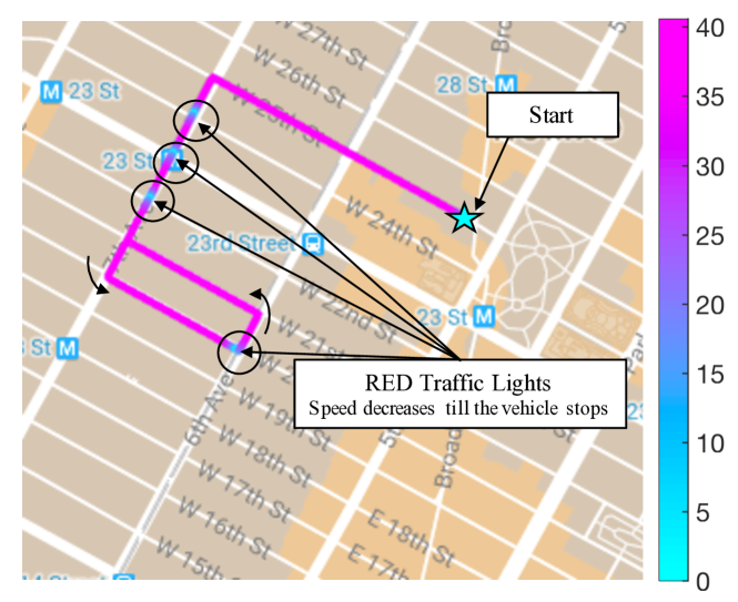
Moreover, in order to consider realistic mobility models and representative speed traces, we simulated the mobility of cars using SUMO [8], a powerful, open-source traffic generator that supports the modeling of intermodal traffic systems including road vehicles and structures, public transports and pedestrians. The vehicles move through the street network (imported from OSM) according to a randomTrip mobility model, which generates trips with random origins and destinations, and speed values which depend on the interaction of the moving vehicle with the road and network elements (e.g., traffic lights or road intersections), as displayed in Fig. 1.
IV-C Simulation Parameters
The simulation parameters are based on realistic system design considerations and are summarized in Table II. The mmWave and LTE RSUs are deployed over an area of 1 km2 (which is deemed sufficient to avoid undesired boundary effects) according to two independent Poisson Point Processes (PPPs) with densities and , respectively. In particular, according to the 3GPP specifications [24], the LTE macro inter-site distance is 500 m, i.e., RSU/km2, while varies from 10 to 100 RSU/km2 (the trade-off oscillates between better coverage and increased deployment cost). We assume the LTE systems operate in the 2 GHz legacy band, with 20 MHz of bandwidth and omnidirectional transmission.
For the mmWave links, instead, we assume to operate at 28 GHz, with 1 GHz bandwidth and (in general) directional transmission. To this end, vehicles and RSUs are equipped with Uniform Planar Arrays (UPAs) of and elements, respectively, allowing to steer beams consisting of a main lobe of predefined width (which depends on and ) and a side lobe that covers the remainder of the antenna radiation pattern.222There exists a strong correlation among number of antenna elements, beam width, and beamforming gain: the more antenna elements in the system, the narrower the beams, the more directional the transmission, and the higher the gain that can be achieved by beamforming. For the sake of completeness, we also consider omnidirectional mmWave transmissions at the vehicle side, which corresponds to . Notice that, in general, , since RSUs are usually less space-constrained than cars.
For the beam alignment, we consider the procedure described in [16], according to which the nodes exchange channel quality reports at the beginning of every slot of duration , so that vehicles and RSUs can regularly identify the optimal directions for their respective beams. In order to minimize the tracking overhead (which might be significant when considering very low values of ), in case the alignment is lost within a slot, connectivity can be recovered only at the beginning of the subsequent slot, i.e., when a new beam alignment operation will be completed. In order to get insights on some limit performance, we will also consider the perfect beam alignment case where the beam alignment procedure is performed continuously () and the beams are hence always perfectly aligned (e.g., thanks to the use of digital beamforming or other external means).
| Parameter | Value | Description |
| dBm | mmWave TX power | |
| GHz | mmWave bandwidth | |
| GHz | mmWave carrier frequency | |
| RSU/km2 | mmWave RSU density | |
| s | Tracking periodicity | |
| Vehicle array size | ||
| mmWave RSU array size | ||
| dBm | LTE TX power | |
| MHz | LTE bandwidth | |
| GHz | LTE carrier frequency | |
| RSU/km2 | LTE RSU density | |
| LTE channel parameters [24] | ||
| mmWave channel parameters [26] | ||
The statistical results are derived through a Monte Carlo approach, where multiple independent simulations are repeated to get different statistical quantities of interest. More specifically, we analyze the received signal strength between a single target transmitting vehicle and its serving infrastructure for different values of . The signal strength is also related to the achievable data rate, which is calculated according to the Shannon formula. Given a bandwidth (either or , according to the technology being considered), and the SNR between the transmitter and its candidate receiver , the average (Shannon) data rate is therefore computed as
| (6) |
V Comparative Results
In the following subsections we provide some numerical results to compare the connectivity performance of LTE and mmWave-based V2N transmissions, which will be evaluated in terms of achievable data rate, stability and outage probability.
In Fig. 2 we compare the two technologies in terms of average data rate experienced by the target vehicle assuming perfect beam alignment for the mmWave links and different antenna configurations (including omnidirectional transmissions at the vehicular node, ). The data rate is computed according to Eq. (6). We observe that the very large bandwidth available to the mmWave systems (50 times larger than in LTE) provides much higher throughput, which may be required by some V2N applications (e.g., high-resolution video streaming). Moreover, even with an omnidirectional mmWave antenna at the vehicular node, the connection can still provide acceptable average bitrate, provided that the mmWave RSUs are sufficiently dense (to increase the LOS probability). Finally, we note that by further increasing , the mutual interference among the RSUs will eventually impact the average bitrate, which will start decreasing.
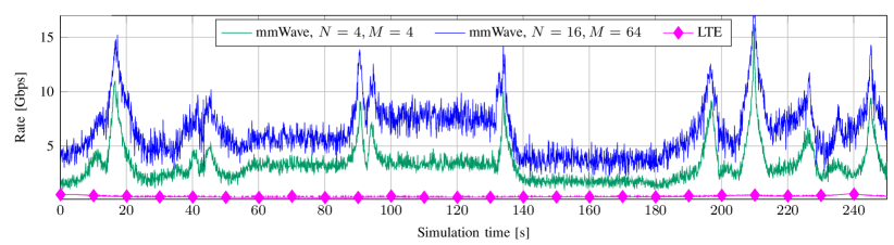
In Fig. 3 we plot the evolution of the transmit rate experienced by a moving vehicle in a specific SUMO simulation of duration s, for two antenna configurations. It is apparent that the mmWave throughput depends on the array factors, i.e., on the beamforming gain. From Fig 3, it is also interesting to observe that the rate traces follow accurately the movements of the car along the streets. For example, the almost constant rate intervals (e.g., from s to s, from s to s, and from s to s) correspond to stopping periods at the red traffic lights, while the peaks correspond to the crossing of the coverage range of the mmWave RSUs, whose range is geometrically determined by their beamwidths. Finally, we observe that the mmWave rate presents clear fluctuations and variations, which are mainly due to transitions from LOS to NLOS, and vice versa, and to the small scale fading.
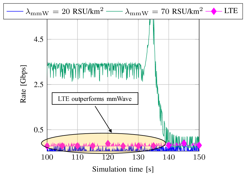
In Fig. 4 we can observe the effect on the transmission rate of different mmWave RSU deployment strategies. As expected, the rate decreases in sparser networks (i.e., with RSU/km2) since vehicles generally need to connect with farther RSUs. In these conditions, LTE can provide better performance (despite the low density of LTE RSUs, equal to RSU/km2).
V-A Stability Performance
Following the analysis we proposed in [28], we measure the stability performance of a link in terms of the coefficient of variation of the transmission rate, which is defined as
| (7) |
where and are the standard deviation and mean, respectively, of the throughput experienced by a certain RT. High values of indicate significant channel instability, meaning that the rate would be affected by local variations and periodic degradations. Let and denote the stability indices (7) for mmWave and LTE links, respectively. From Fig. 5 we observe that for all values of , which reflects the much higher variability of the performance guaranteed by mmWave links as a result of the scattering from nearby buildings, vehicles and terrain surfaces. These variations may actually hinder the adoption of mmWave links to support some types of V2N applications, especially those requiring long-term stable throughput (e.g., real-time services). However, the stability of the mmWave links increases in dense environments, as the probability of path loss outage decreases.
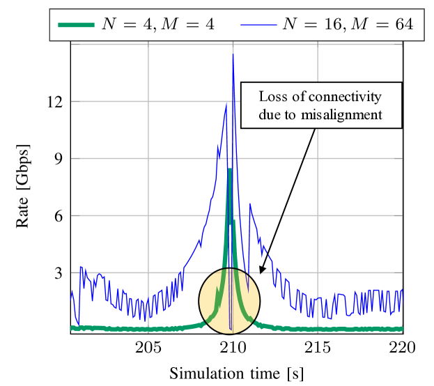
In case of directional mmWave transmissions, the misalignment between the transmitter and the receiver can also significantly impact the link stability, as exemplified in Fig. 6 which shows the rate achieved by the mmWave link when changing the beam tracking period. As increases, the rate presents significant variations which, in some cases, may lead to network disconnections. Conversely, the omnidirectional transmissions of LTE systems offer more stable connectivity and, under some circumstances, even higher throughput than mmWave strategies.
The extent to which beam misalignment impacts the communication performance depends on several factors, including the beamwidth, as illustrated in Fig. 7. Wider beams provide more durable connections (even with very sporadic beam tracking), as they enlarge the area in which the vehicles can benefit from the coverage of their serving cells before disconnecting. In this context, however, the well-known stability versus data rate trade-off arises: the narrower the beams, the higher but less stable the transmission rates.
V-B Outage probability
In Fig. 8 we evaluate the outage probability of the investigated V2N schemes, i.e., the probability that the received signal strength is below a predefined threshold. We first observe that the outage probability for mmWave transmissions decreases monotonically with the RSU density (because of the closer distance between transmitter and receiver), and with the number of antenna elements at the nodes (because of the higher beamforming gain). Moreover, we notice that the outage probability of mmWave links degrades significantly when the vehicle has only one omnidirectional antenna (), while LTE provides more reliable communications, with lower outage probability.
VI Conclusion and Future Work
A limitation for the feasibility of mmWave-enabled V2N communication is the rapid dynamics of the mmWave channel and the high risk of misalignment between the communication endpoints caused by user mobility when using narrow beams. The vehicle may be suddenly in outage with respect to all the surrounding RSUs and, in some scenarios, this may prevent the timely dissemination of data. In this paper, we have compared the performance of LTE and mmWave technologies in terms of achievable data rate, communication stability and outage probability. Our results showed that LTE systems provide limited data rates (i.e., up to a few hundreds of Mbps) but guarantee stable and reliable transmissions thanks to the intrinsic stability of the low-frequency channels and the omnidirectional transmissions. Conversely, mmWave networks offer high-capacity but highly variable connectivity, though their performance can be improved by considering very directional transmissions and frequent re-alignment operations, and by increasing the infrastructure density.
From our analysis we conclude that a practical way to complement the limitations of each type of network is via heterogeneous networking, i.e., by combining multiple radio access technologies into a single solution that is more robust and efficient than any individual approach.
The performance of V2N communications can be improved by designing advanced multi-RT schemes able to instantaneously identify the best access solution to interconnect the vehicles and the infrastructure(s), or by envisioning synergistic combinations of the two approaches, e.g., exploiting LTE to help beam alignment of mmWave links, or using the two technologies in parallel to transmit layered content. These research challenges are left for future work.
References
- [1] 3GPP, “Technical Specification Group Services and System Aspects; Enhancement of 3GPP support for V2X scenarios; Stage 1 (Release 15),” TS 22.186, 2017.
- [2] H. Hartenstein and K. Laberteaux, VANET vehicular applications and inter-networking technologies. John Wiley & Sons, 2009.
- [3] J. B. Kenney, “Dedicated Short-Range Communications (DSRC) Standards in the United States,” Proceedings of the IEEE, vol. 99, no. 7, pp. 1162–1182, Jul 2011.
- [4] G. Araniti, C. Campolo, M. Condoluci, A. Iera, and A. Molinaro, “LTE for vehicular networking: a survey,” IEEE Communications Magazine, vol. 51, no. 5, pp. 148–157, May 2013.
- [5] V. Va, T. Shimizu, G. Bansal, and R. W. Heath, “Millimeter wave vehicular communications: A survey,” Foundations and Trends® in Networking, vol. 10, no. 1, pp. 1–113, 2016. [Online]. Available: http://dx.doi.org/10.1561/1300000054
- [6] J. Choi, V. Va, N. Gonzalez-Prelcic, R. Daniels, C. R. Bhat, and R. W. Heath, “Millimeter-Wave Vehicular Communication to Support Massive Automotive Sensing,” IEEE Communications Magazine, vol. 54, no. 12, pp. 160–167, December 2016.
- [7] T. S. Rappaport, R. W. Heath Jr, R. C. Daniels, and J. N. Murdock, Millimeter wave wireless communications. Pearson Education, 2014.
- [8] D. Krajzewicz, J. Erdmann, M. Behrisch, and L. Bieker, “Recent development and applications of SUMO - Simulation of Urban MObility,” International Journal On Advances in Systems and Measurements, vol. 5, no. 3&4, pp. 128–138, December 2012.
- [9] 3GPP, “Requirements for Evolved UTRA and Evolved UTRAN (Release 7) ,” TR 25.913, 2015.
- [10] A. Kato, K. Sato, and M. Fujise, “ITS wireless transmission technology. Technologies of millimeter-wave inter-vehicle communications: Propagation characteristics,” Journal of the Communications Research Laboratory, vol. 48, pp. 99–110, March 2001.
- [11] A. Yamamoto, K. Ogawa, T. Horimatsu, A. Kato, and M. Fujise, “Path-loss prediction models for intervehicle communication at 60 GHz,” IEEE Transactions on Vehicular Technology, vol. 57, no. 1, pp. 65–78, 2008.
- [12] J. Hasch, E. Topak, R. Schnabel, T. Zwick, R. Weigel, and C. Waldschmidt, “Millimeter-Wave Technology for Automotive Radar Sensors in the 77 GHz Frequency Band,” IEEE Transactions on Microwave Theory and Techniques, vol. 60, no. 3, pp. 845–860, March 2012.
- [13] S. Shah, E. Ahmed, M. Imran, and S. Zeadally, “5G for Vehicular Communications,” IEEE Communications Magazine, vol. 56, no. 1, pp. 111–117, Jan 2018.
- [14] N. Lu, N. Cheng, N. Zhang, X. Shen, and J. W. Mark, “Connected Vehicles: Solutions and Challenges,” IEEE Internet of Things Journal, vol. 1, no. 4, pp. 289–299, Aug 2014.
- [15] M. Giordani, A. Zanella, and M. Zorzi, “Millimeter wave communication in vehicular networks: Challenges and opportunities,” in 6th International Conference on Modern Circuits and Systems Technologies (MOCAST), May 2017.
- [16] M. Giordani, M. Rebato, A. Zanella, and M. Zorzi, “Coverage and Connectivity Analysis of Millimeter Wave Vehicular Networks,” submitted to Ad Hoc Networks, 2018. [Online]. Available: https://arxiv.org/abs/1803.01136
- [17] V. Va, T. Shimizu, G. Bansal, and R. W. Heath, “Beam design for beam switching based millimeter wave vehicle-to-infrastructure communications,” in IEEE International Conference on Communications (ICC), May 2016.
- [18] N. Garcia, H. Wymeersch, E. G. Strom, and D. Slock, “Location-aided mm-wave channel estimation for vehicular communication,” in IEEE 17th International Workshop on Signal Processing Advances in Wireless Communications (SPAWC), July 2016.
- [19] M. Sepulcre, J. Gozalvez, O. Altintas, and H. Kremo, “Context-aware heterogeneous V2I communications,” in 7th International Workshop on Reliable Networks Design and Modeling (RNDM), Oct 2015, pp. 295–300.
- [20] F. Dressler, H. Hartenstein, O. Altintas, and O. K. Tonguz, “Inter-vehicle communication: Quo vadis,” IEEE Communications Magazine, vol. 52, no. 6, pp. 170–177, June 2014.
- [21] 3GPP, “Technical Specification Group Services and System Aspects; Study on enhancement of 3GPP Support for 5G V2X Services (Release 15),” TS 22.886, 2017.
- [22] S. Rangan, T. S. Rappaport, and E. Erkip, “Millimeter-wave cellular wireless networks: Potentials and challenges,” Proceedings of the IEEE, vol. 102, no. 3, pp. 366–385, March 2014.
- [23] C. Wang and H.-M. Wang, “Physical layer security in millimeter wave cellular networks,” IEEE Transactions on Wireless Communications, vol. 15, no. 8, pp. 5569–5585, 2016.
- [24] 3GPP, “Study on Small Cell enhancements for E-UTRA and E-UTRAN; Higher layer aspects (Release 12) ,” TR 36.842, 2014.
- [25] S. Geng, J. Kivinen, X. Zhao, and P. Vainikainen, “Millimeter-Wave Propagation Channel Characterization for Short-Range Wireless Communications,” IEEE Transactions on Vehicular Technology, vol. 58, no. 1, pp. 3–13, Jan 2009.
- [26] M. R. Akdeniz, Y. Liu, M. K. Samimi, S. Sun, S. Rangan, T. S. Rappaport, and E. Erkip, “Millimeter Wave Channel Modeling and Cellular Capacity Evaluation,” IEEE Journal on Selected Areas in Communications, vol. 32, no. 6, pp. 1164–1179, June 2014.
- [27] OpenStreetMap (OSM). [Online]. Available: http://www.openstreetmap.org/
- [28] M. Polese, M. Giordani, M. Mezzavilla, S. Rangan, and M. Zorzi, “Improved Handover through Dual Connectivity in 5G mmWave mobile networks,” IEEE Journal on Selected Areas in Communications, vol. 35, no. 9, pp. 2069–2084, Sept 2017.