Standalone and Non-Standalone
Beam Management for 3GPP NR at mmWaves
Abstract
The next generation of cellular networks will exploit mmWave frequencies to dramatically increase the network capacity. The communication at such high frequencies, however, requires directionality to compensate the increase in propagation loss. Users and base stations need to align their beams during both initial access and data transmissions, to ensure the maximum gain is reached. The accuracy of the beam selection, and the delay in updating the beam pair or performing initial access, impact the end-to-end performance and the quality of service. In this paper we will present the beam management procedures that 3GPP has included in the NR specifications, focusing on the different operations that can be performed in Standalone (SA) and in Non-Standalone (NSA) deployments. We will also provide a performance comparison among different schemes, along with design insights on the most important parameters related to beam management frameworks.
Index Terms:
5G, mmWave, initial access, tracking, 3GPP, NR.I Introduction
In order to satisfy the expected growth in capacity demand [1], the fifth generation of cellular networks (5G) will adopt for the first time communication at mmWaves in a truly mobile access scenario, thanks to the support of frequencies up to 52.6 GHz in 3GPP Release 15 for NR [2]. In this band, indeed, there are large chunks of untapped spectrum that can be allocated to the cellular radio access to boost the available data rate and increase the network capacity [3].
The communication at such high frequencies, however, introduces new challenges for the whole protocol stack, which could affect the end-to-end performance and the quality of experience perceived by the users. The main issues are related to the harsh propagation environment, characterized by high propagation loss and sensitivity to blockage from common materials [3]. In order to overcome these problems, the NR standard includes new Physical (PHY) and Medium Access Control (MAC) layer operations, related to the support of directional communications [4], and new deployment options related to multi-connectivity and inter-networking with legacy sub-6 GHz network such as Long Term Evolution (LTE) [5].
Directional communications are enabled by antenna arrays with a large number of elements, which are feasible at mmWaves thanks to the small wavelength. They provide an additional beamforming gain to the link budget, compensating for the increase in propagation loss, and possibly enabling spatial multiplexing [3]. Directional links, however, need accurate alignment of the transmitter and the receiver beams, a procedure which might introduce a delay to access the network and to update the beam pair, thus impacting the overall end-to-end performance. Therefore, reliable networks will need robust and optimized beam management operations, both for Initial Access (IA), i.e., when the User Equipment (UE) is not connected, and for tracking, i.e., when the UE is exchanging data with the network.
Multi-connectivity solutions have also been shown to improve the end-to-end performance in mmWave networks, by combining a reliable sub-6 GHz link (e.g., on LTE) with a high capacity mmWave connection [6]. Additionally, the Non-Standalone (NSA) deployment option [5], in which LTE and Evolved Packet Core (EPC) are used as a radio overlay and as core network also for NR base stations, has been introduced to ease the deployment of NR.
In this article, we will discuss beam management frameworks for NR at mmWave frequencies, focusing in particular on the benefits that multi-connectivity may introduce. We will compare the operations supported by NR Standalone (SA) and NSA deployments at mmWaves, and their performance. We show that exploiting sub-6 GHz frequencies reduces the latency in beam reporting during IA and in the reaction to Radio Link Failure (RLF). On the other hand, thanks to the robust signaling structure designed for NR, the SA option exhibits a good performance for IA, even though it is more dependent than NSA on the network and antenna array configurations111For a more technical discussion and an extensive set of results we refer the interested reader to [7].. In this context, some recent works (e.g., [8, 9]) have provided an overview of the key features pertaining to IA and beam management for 5G NR networks currently being standardized by the 3GPP. In [8], the authors focus on a user-centric coordinated transmission mechanism able to realize seamless intra and inter-cell handover and IA operations, and to reduce the interference levels across the network. In [9] the use of analog and digital beamforming architectures is investigated as a means to support high-resolution channel state information exchange to deliver efficient beam management procedures. Our work is distinguished from the aforementioned references as we now investigate, in a single contribution, the performance and the architectural implementation of beam management for users both in idle and in connected mode, to enable IA and tracking operations, respectively. Moreover, unlike previous papers, this is the first contribution in which both SA and NSA deployments are considered and compared for beam management.
The remainder of the paper is organized as follows. In Sec. II we provide a brief overview on the main NR novelties, and in Sec. III we describe the NR beam management operations. In Sec. IV we report a performance evaluation, and discuss the influence of beam management configurations on the overall results. Finally, in Sec. V we conclude the paper and suggest possible avenues for future work.
II 3GPP NR
NR and 5G Core (5GC) are, respectively, the 3GPP standards for the Radio Access Network (RAN) and the core network of 5G networks. Their main characteristic is flexibility: the standard, indeed, provides a general technology framework designed to address the different and, in some cases, conflicting 5G requirements [1] and to be forward compatible, so that it can accommodate future applications and use cases. Therefore, the main novelties with respect to LTE in the RAN are (i) a more flexible frame structure; (ii) the support of a much larger spectrum, with frequencies also in the mmWave band (up to 52.6 GHz); and (iii) the design of PHY and MAC layer procedures for beam management [4, 2], which we will describe in Sec. III. In the core network, instead, the new 5GC introduces network slicing and a higher level of flexibility and virtualization with respect to the traditional LTE EPC. Moreover, different deployment options and inter-networking with LTE are supported.
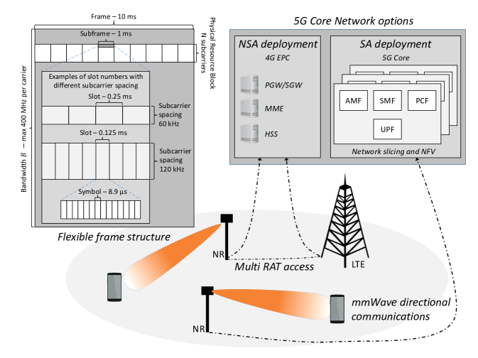
Fig. 1 summarizes the main 5G novelties for mobile cellular networks and, in the following paragraphs, we will introduce the main novelties related to the NR frame structure and the 5G deployment architectures, focusing on how they can support mmWave communications.
II-A NR Frame Structure
The main characteristics of the frame structure can be found in [4]. The waveform will be Orthogonal Frequency Division Multiplexing (OFDM) with a cyclic prefix, and, in general, the frame structure is based on time and frequency sub-divisions similar to those of LTE, with a frame of 10 ms composed of 10 subframes. However, the main novelty with respect to LTE is flexibility: NR supports multiple numerologies, i.e., sets of parameters for the OFDM waveform, also multiplexed in time and frequency, as long as they are aligned on a subframe basis. This makes it possible to target the different 5G use cases: for example, a shorter OFDM symbol duration, combined with a higher subcarrier spacing, can be used for high-data-rate and low-latency traffic, while lower subcarrier spacing can be used for low-frequency narrowband communications for machine-generated traffic.
The top-left corner of Figure 1 shows an example of NR frame structure. The maximum bandwidth for a single carrier is 400 MHz, and it is possible to aggregate up to 16 carriers. In time, each subframe is composed by slots, with ranging from 0 to 4. This parameter controls also the subcarrier spacing, which is given by kHz. For frequencies above 6 GHz, the minimum value of is 2, therefore the minimum subcarrier spacing is 60 kHz. In time, each slot contains 14 OFDM symbols, but also mini-slots are supported: they can last as little as 2 OFDM symbols, have variable length, and can be positioned asynchronously with respect to the beginning of a standard slot. They are designed for ultra-low latency communications, so that the data transmission does not need to wait for the beginning of the next slot.
Another important novelty is that a subframe can be self-contained, meaning that a complete round-trip transmission with a first transmission and the corresponding acknowledgment can happen in a single subframe. Therefore, NR supports sub-ms latency for acknowledged transmissions.
II-B 5G Network Deployment
The flexibility provided by the 3GPP specifications extends to the possible deployment architectures and interconnectivity between 4G and new 5G networks, as shown in Fig 1. In particular, in order to smooth the transition between the different generations and reuse the widely deployed LTE and EPC infrastructure, the NR specifications foresee a NSA deployment, in which the network operator only deploys NR Next Generation Node Base Stations (gNBs) which are connected to EPC, possibly with a Dual Connectivity (DC) setup aided by LTE. The other option is an SA deployment, in which both the RAN and the core network respect 5th generation (5G) specifications. When it comes to deployments at mmWave frequencies, the NSA option with DC across different Radio Access Technologies (RATs) can also be particularly beneficial to improve the network performance, as shown in [6]. The so-called E-UTRAN-NR DC (EN-DC) [5] is an extension of the DC already standardized in LTE networks, and allows a UE to transmit and receive data from different base stations, belonging to an LTE and an NR deployment, with independent schedulers, possibly connected by a non-ideal (i.e., with limited data rate and additional latency) backhaul link. In particular, with EN-DC the core network is the EPC, but 3GPP will standardize also a multi RAT DC option with 5GC. There is the possibility of performing inter-RAT measurement and coordination of the user mobility in the different RATs, and to use service radio bearers for control only on LTE, so that the mobility management at mmWave frequencies can be aided by the control plane at lower frequencies.
III Beam Management in 3GPP NR
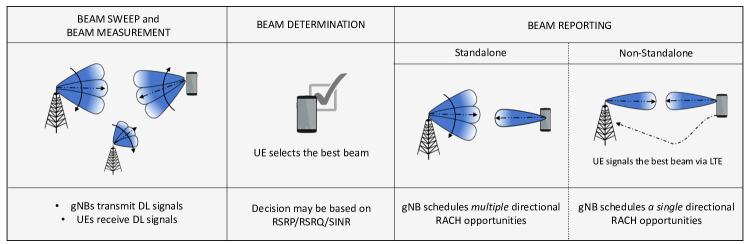
MmWave communication systems typically implement directional transmissions, e.g., using high-dimensional phased arrays, to benefit from the resulting beamforming gain and compensate for the increased path loss experienced at high frequencies. Therefore, next-generation cellular networks must provide a mechanism by which UEs and gNBs regularly identify the optimal beams to interconnect at any given time. To this goal, the 3GPP has specified a set of basic procedures for the control of multiple beams at NR frequencies above 6 GHz which are categorized under the term beam management [7]. In line with the 3GPP design for NR, we consider a downlink architecture where the synchronization and reference signals (i.e., Synchronization Signal (SS) blocks and Channel State Information - Reference Signals (CSI-RSs), respectively) are broadcast by the gNBs and received by the UEs within reach. In particular, the following four operations are defined:
-
•
Beam sweeping, i.e., the covering of a spatial area with a set of beams transmitted and received according to pre-specified intervals and directions.
-
•
Beam measurement, i.e., the evaluation of the quality of the received signal, which can be expressed in terms of Reference Signal Received Power (RSRP)– the linear average of the received power on different resources with synchronization signals, the Reference Signal Received Quality (RSRQ)– the ratio between the RSRP and the Received Signal Strength Indicator (RSSI), a measurement that includes also thermal noise and signals from other sources, or the Signal to Interference plus Noise Ratio (SINR) [10].
-
•
Beam determination, i.e., the selection of the optimal beam (or set of beams) to set up a directional (and fully beamformed) communication.
-
•
Beam reporting, i.e., the procedure with which the nodes send to the RAN information on the quality of the received beamformed signals and on their decision in the beam determination phase.
For idle users, beam management is fundamental to design a directional initial access strategy, which allows the UE to establish a physical link connection when it first accesses the network [11, 7]. For users in connected mode, as the dynamics of the mmWave channel imply that the directional path to any cell can deteriorate rapidly, beam management is required to maintain precise alignment of the transmitter and receiver beams as the UEs move, an operation that resembles handover and which is referred to as tracking [6].
In this context, after reviewing in Sec. III-A the most relevant measurement signals supported by 3GPP NR for beam management, in Sec. III-B we present SA and NSA operations for both IA and tracking purposes.
III-A Downlink Measurement Signals for Beam Management
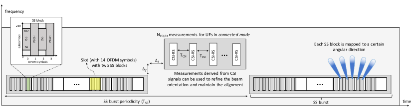
The structure of the measurement signals considered in the following paragraphs is graphically represented in Fig. 2.
SS Blocks. In LTE systems, the synchronization procedure relies on two specifically designed physical signals, which are broadcast omnidirectionally in the downlink, namely the Primary Synchronization Signal (PSS) and the Secondary Synchronization Signal (SSS). Each UE in the cell is aware a priori of when and where the synchronization control channel is and can extract and detect those signals.
Along these lines, the 3GPP has defined a directional version of such signals introducing the concept of SS blocks and bursts [4]. An SS block is a group of 4 OFDM symbols [4] in time and 240 subcarriers in frequency (i.e., 20 resource blocks) with the PSS, the SSS and the Physical Broadcast Channel (PBCH) that can be used to estimate the RSRP and select the optimal beam to communicate. The SS blocks are grouped into the first 5 ms of an SS burst, which can have different periodicities ms [12]. The maximum number of SS blocks in a burst is frequency-dependent, and above 6 GHz there could be up to 64 blocks per burst.
When considering frequencies that need directional transmissions, each gNB transmits directionally the SS blocks, by sequentially sweeping different angular directions to cover a whole cell sector. Based on the measured quality of the received signal, the SS blocks can be exploited by both idle users to identify their initial directions of transmission (in this case, to reduce the impact of SS transmissions and guarantee prompt network access operations, SS can be sent through wide beams) and connected users for beam tracking purposes.
CSI-RS. In LTE, CSI-RSs allow connected UEs to regularly estimate the channel conditions and report Channel Quality Information (CQI) to their serving base station. Likewise, in NR, these signals can be used as Radio Resource Management (RRM) measurements for mobility management purposes in connected mode [2]. However, it is fundamental for the UEs to know in which time and frequency resources the CSI-RSs signals will be sent: as long as each CSI-RS is represented by a unique identifier, it shall be possible to configure multiple CSI-RSs to the same SS burst, in such a way that the UE can first obtain synchronization with a given cell using the SS bursts, and then use that as a reference to search for CSI-RS resources. The CSI-RSs configuration should also contain at least the periodicity and time/frequency offsets relative to the associated SS burst.
Regarding the bandwidth, although an NR network may be able to transmit CSI-RS measurements in full bandwidth, in some deployment scenarios the reference signals may be broadcast through a subset of all the available frequency resources (with a minimum of 50 resource blocks [13]) which is deemed sufficiently large to allow proper channel estimation at the receiver.
Regarding the time allocation, CSI-RSs may span 1, 2 or 4 OFDM symbols [4]. Moreover, the 3GPP defines different activation methodologies for the CSI-RS measures. For periodic or semi-persistent CSI-RS transmissions, the following periodicities (measured in slots) are supported: [4]. For semi-persistent and aperiodic CSI-RS transmissions, the resources are configured and pre-allocated by the higher layers, while their persistent counterparts assume that measurement signals are broadcast with regularity. For aperiodic transmissions, a single set of CSI-RS triggering states is higher-layer configured, therefore a UE is not expected to receive more than one aperiodic CSI-RS in a given slot, i.e., it is not expected to transmit more than one aperiodic CQI report to its serving cell [13]. It should be noted that CSI-RSs may have a significantly higher time/frequency density compared to that of the SS blocks, thus implying higher overhead but, at the same time, higher flexibility.
When considering beamformed communications, the CSI-based results assume a crucial role if they are properly associated with the SS measurements. In this approach, as far as the transceiver has already identified a suitable beam pair to establish a directional transmission, the measurements derived from the CSI-RS signals corresponding to different angular directions can be used to refine the beam orientation and maintain the alignment between the communication nodes when considering network topology changes and dynamic evolution of the channel.
III-B Standalone vs. Non-Standalone Beam Management
In this subsection, we focus on the differences between SA and NSA deployments for the beam management of users both in idle and in connected mode, as illustrated in Fig. 3.
Idle Mode. Referring to the list of operations described in Sec. III for beam management, we claim that the NSA functionality enables an improvement in the beam reporting phase, which allows the UE to disseminate the beam quality and beam decision information to the RAN. In order to do so, the mobile terminal has to wait for its candidate serving gNB to schedule a Random Access Channel (RACH) opportunity towards the best direction it has selected during the beam determination phase to perform random access. If an SA deployment is preferred, this may require an additional complete directional scan of the gNB, thus further increasing the time it takes to access the network.222It has been agreed that, for each SS block, the gNB will specify one or more RACH opportunities with a certain time and frequency offset and direction, so that the UE knows when to transmit the RACH preamble [2]. On the other hand, leveraging the support of the LTE overlay offered by the NSA architecture, the UE can inform the selected serving infrastructure of the optimal direction (or set of directions) through which it has to steer its beam, in order to be properly aligned, through the legacy LTE connection. A single RACH opportunity with full beamforming capabilities can therefore be immediately scheduled for that direction, without the need to wait for an additional beam sweep at the gNB side.
Connected Mode. When the quality of an associated control channel falls below a predefined threshold, i.e., in the case of RLF, mechanisms to recover acceptable communication capabilities (e.g., by updating the steering direction of the network nodes or, as a last resort, by handing over to a more robust gNB) need to be quickly triggered upon notifying the network. We assess that faster and more efficient RLF recovery operations are guaranteed if an NSA architecture is preferred over an SA one. As soon as an impairment is detected, in the case of SA deployments the UE may not be able to properly inform its serving gNB since the optimal directional path connecting the endpoints is affected by the failure. As a consequence, a recovery phase can only be triggered when a new beam configuration is determined, i.e., after the completion of an IA operation. This may take up to several tens of milliseconds. Conversely, if the failure notification is forwarded through the robust LTE overlay (i.e., by implementing an NSA-based measurement framework), the RLF recovery delay is equal to the latency of a traditional LTE connection, which may be significantly lower than the time it takes to perform IA. The LTE radio may also serve the UE’s traffic requests until the mmWave directional communication is successfully restored, thereby offering continuous connectivity even during link failures.
The performance of the SA and NSA architectures will be numerically assessed and compared in Sec. IV.
IV Design Considerations and Results
In this section we provide some general guidelines for the selection of the beam management parameters described in Sec. III, and we compare the performance of the SA and NSA architectures for beam reporting and RLF recovery operations. We refer to [7] for a complete analysis of the different beam management schemes for NR.
General Discussion. The most important metrics to be considered when evaluating the performance of the beam management schemes are detection accuracy, reactiveness and overhead, as shown in Fig. 4. The accuracy represents the capability of the framework to identify and correctly measure the beams, and is inversely proportional to the probability of misdetection, i.e., the probability of not detecting the beam. The reactiveness, instead, describes how quickly the framework is able to detect an updated channel condition, and is inversely proportional to the average time required to find the best beam pair, during the IA, and to the average time to receive a CSI-RS in a certain direction for the tracking of already connected users. Finally, the overhead is the ratio between the number of time and frequency resources that should be allocated to beam management operations (instead of data transmission) and all the available resources. Although these metrics are apparently orthogonal there exist some configurations that are able to provide performance gains on different metrics, jointly.
In this context, the beamforming architectures and the number of antennas at the gNBs and the UEs (i.e., and , respectively) are key parameters in the design of directional initial access and tracking. From Fig. 4(a), we observe that a larger number of antennas enables narrower beams which, in turn, guarantee better accuracy (thanks to the higher gains achieved by beamforming). On the other hand, highly directional communications lead to worse performance in terms of reactiveness and overhead (due to the increased number of directions that need to be scanned before the optimal beam configuration is selected). A digital beamforming architecture (which allows the processing of the received signals in the digital domain, enabling the transceiver to generate beams in multiple directions at the same time) has the potential to improve the reactiveness of the measurement scheme and decrease the overhead, without penalizing the accuracy. However, it suffers from increased power consumption with respect to an analog strategy.333For completeness, it should be mentioned that the 5G equipment manufacturers are also considering a hybrid beamforming solution, which uses radio-frequency chains and enables the transceiver to transmit/receive in directions simultaneously. Nevertheless, when hybrid beamforming is used for transmission, the power available at each transmitting beam is the total node power constraint divided by , thus potentially reducing the received power.
The setup of the maximum number of SS blocks in a burst (i.e., ) and the SS burst periodicity (i.e., ) has also a remarkable impact in terms of reactiveness and overhead, as represented in Fig. 4(b). A higher number of SS blocks per burst, although increasing the overhead linearly, increases the probability of completing the sweep in a single burst and thus reduces the time it takes to perform IA. In these circumstances, a higher would guarantee more reactive tracking operations and reduce the overhead of the SS blocks, as shown by the “IA overhead” axis in Fig. 4(b).
| Standalone | Non Standalone | |||||
| [W] | [W] | |||||
| Analog | Digital | Analog | Digital | |||
| 4 | 0.0894 | 0.0894 | 16.2847 | 64.359 | 0.0894 | 16.2847 |
| 16 | 0.7149 | 0.0894 | 135.8934 | 257.433 | 0.0894 | 16.9867 |
| 64 | 2.2341 | 0.0894 | 494.8670 | 1030.74 | 0.0894 | 19.7947 |
| Antenna | [ms] | |||
|---|---|---|---|---|
| , gNB ABF, UE ABF | , gNB DBF, UE ABF | , gNB DBF, UE ABF | ||
| 4 | 4 | 30.2322 | 20.3572 | 40.3572 |
| 64 | 1 | 130.1072 | 20.0535 | 40.0535 |
| 64 | 16 | 5250 | 22.6072 | 42.6072 |
| ms, according to the considerations in [14]. | ||||
NSA vs. SA. As discussed in Sec. III-B, the design of an NSA-like framework for beam management may be preferable in many respects. First, as illustrated in Fig. 5(a), although the SA architecture generally presents low beam reporting delays , an NSA scheme may guarantee faster reporting operations in case of large antenna arrays at the gNB side, i.e., when configuring very narrow beams which would inevitably increase the number of directions to scan before a RACH opportunity is scheduled towards the correct random access direction. For the NSA case, the beam reporting delay is equal to the latency of an LTE connection which, assuming no retransmissions are needed, ranges from 10.5 ms to 0.8 ms, according to the latency reduction techniques being implemented [7]. Notice that the results are independent of since the UE has already selected its optimal steering direction and therefore does not require a beam sweeping operation.
Second, from Fig. 5(b), we observe that an NSA architecture can reduce the impact of the beam reporting overhead while delivering more power-efficient operations. For the SA case, the overhead may increase significantly, especially if analog beamforming is implemented, since the completion of the random access requires the system to scan through all directions one by one, thereby requiring the allocation of possibly multiple RACH resources. On the other hand, an NSA scheme necessitates a single RACH opportunity – regardless of the beamforming architecture being implemented – with a total overhead of . It should be noticed that, while this overhead may seem small, it represents that of a RACH opportunity for a single user, and not the overall overhead of IA procedures [7]. Moreover, we recall that the SA overhead may be reduced as configuring a digital beamforming architecture, which enables the transceiver to direct beams at multiple directions simultaneously, thereby removing the need for a directional scan at the gNB side during random access. However, digital beamforming requires a separate Radio Frequency (RF) chain for each antenna element and therefore shows much higher power consumption than if analog beamforming were preferred.444The total power consumption of each beamforming scheme is evaluated according to [15] in which quantization bits are used by the Analog-to-Digital Converter block.
Third, Tab. I exemplifies how, in connected mode, an NSA implementation offers reactive recovery operations in the case of radio link failure events. We observe that, for the SA case, the RLF recovery delay is quite high for all the investigated settings and is dominated by the IA delay. In some circumstances (e.g., , ms, and when analog beamforming is implemented), the RLF recovery delay assumes unacceptably high values. For the NSA case, instead, the RLF recovery delay is equal to the latency of a traditional LTE connection (which depends on the implemented latency reduction technique) which, in general, is remarkably lower than the IA delay.
V Conclusions
A challenge for the feasibility of 5G cellular systems operating at mmWaves is the rapid channel dynamics that affect a high-frequency environment and the need to maintain alignment between the communication endpoints. In this regard, the design and configuration of efficient initial access and tracking procedures able to periodically identify the optimal beam pair with which a base station and a mobile terminal communicate is of extreme importance. In this paper, after a general description of the main parameters and reference signals specified by the 3GPP for NR, we compared the performance of a standalone and non-standalone deployment for the management of the beams of users both in connected and in idle modes. We showed that an NSA configuration exploiting multi-connectivity offers improved end-to-end performance in mmWave networks and has the potential to (i) guarantee higher resilience and improved reactiveness in case radio link failures occur, (ii) reduce the impact of the overhead in the beam reporting phase, and (iii) deliver more reactive reporting operations.
References
- [1] A. Osseiran, F. Boccardi, V. Braun, K. Kusume, P. Marsch, M. Maternia, O. Queseth, M. Schellmann, H. Schotten, H. Taoka, H. Tullberg, M. A. Uusitalo, B. Timus, and M. Fallgren, “Scenarios for 5G mobile and wireless communications: the vision of the METIS project,” IEEE Communications Magazine, vol. 52, no. 5, pp. 26–35, May 2014.
- [2] 3GPP, “NR and NG-RAN Overall Description - Rel. 15,” TS 38.300, 2018.
- [3] S. Rangan, T. S. Rappaport, and E. Erkip, “Millimeter-Wave Cellular Wireless Networks: Potentials and Challenges,” Proceedings of the IEEE, vol. 102, no. 3, pp. 366–385, March 2014.
- [4] 3GPP, “NR - Physical channels and modulation - Release 15,” TS 38.211, V15.0.0, 2018.
- [5] ——, “NR - Multi-connectivity - Overall description (Stage 2),” TS 37.340, 2018.
- [6] M. Polese, M. Giordani, M. Mezzavilla, S. Rangan, and M. Zorzi, “Improved Handover Through Dual Connectivity in 5G mmWave Mobile Networks,” IEEE Journal on Selected Areas in Communications, vol. 35, no. 9, pp. 2069–2084, Sept 2017.
- [7] M. Giordani, M. Polese, A. Roy, D. Castor, and M. Zorzi, “A Tutorial on Beam Management for 3GPP NR at mmWave Frequencies,” submitted to IEEE Communications Surveys & Tutorials, 2018. [Online]. Available: https://arxiv.org/abs/1804.01908
- [8] J. Liu, K. Au, A. Maaref, J. Luo, H. Baligh, H. Tong, A. Chassaigne, and J. Lorca, “Initial Access, Mobility, and User-Centric Multi-Beam Operation in 5G New Radio,” IEEE Communications Magazine, vol. 56, no. 3, pp. 35–41, March 2018.
- [9] E. Onggosanusi, M. S. Rahman, L. Guo, Y. Kwak, H. Noh, Y. Kim, S. Faxer, M. Harrison, M. Frenne, S. Grant, R. Chen, R. Tamrakar, and a. Q. Gao, “Modular and High-Resolution Channel State Information and Beam Management for 5G New Radio,” IEEE Communications Magazine, vol. 56, no. 3, pp. 48–55, March 2018.
- [10] 3GPP, “NR - Physical layer measurements - Rel. 15,” TS 38.215, 2017.
- [11] M. Giordani, M. Mezzavilla, and M. Zorzi, “Initial access in 5G mmWave cellular networks,” IEEE Communications Magazine, vol. 54, no. 11, pp. 40–47, November 2016.
- [12] 3GPP, “NR - Radio Resource Control (RRC) protocol specification - Release 15,” TS 38.331, 2017.
- [13] ——, “NR - Physical layer procedures for data - Release 15,” TS 38.214, 2018.
- [14] K. Takeda, L. H. Wang, and S. Nagata, “Latency Reduction toward 5G,” IEEE Wireless Communications, vol. 24, no. 3, pp. 2–4, June 2017.
- [15] W. B. Abbas and M. Zorzi, “Towards an Appropriate Receiver Beamforming Scheme for Millimeter Wave Communication: A Power Consumption Based Comparison,” in 22th European Wireless Conference, May 2016.