Dual-wavelength fiber Fabry-Perot cavities with engineered birefringence
Sébastien Garcia,1 Francesco Ferri,1 Konstantin Ott,1,2 Jakob Reichel,1 and Romain Long 1,*
1Laboratoire Kastler Brossel, ENS–Université
PSL, CNRS, Sorbonne Université, Collège de France,
24 rue Lhomond, 75005 Paris, France
2LNE-SYRTE, Observatoire de Paris–Université PSL, CNRS,
Sorbonne Université, 61 Avenue de l’Observatoire, 75014 Paris, France
*long@lkb.ens.fr
Abstract
We present a method to engineer the frequency splitting of polarization eigenmodes in fiber Fabry-Perot (FFP) cavities. Using specific pattern of multiple CO2 laser pulses, we machine paraboloidal micromirrors with controlled elliptical shape in a large range of radii of curvature. This method is versatile and can be used to produce cavities with maximized or near-zero polarization mode splitting. In addition, we realize dual-wavelength FFP cavities with finesse exceeding at 780 nm and at 1559 nm in the telecom range. We provide direct evidence that the birefringent frequency splitting in FFP cavities is governed only by the geometrical shape of the mirrors, and that the astigmatism of the cavity modes needs to be taken into account for specific cavities.
OCIS codes: (060.2310) Fiber optics; (120.2230) Fabry-Perot; (140.3945) Microcavities; (230.4040) Mirrors; (260.1440) Birefringence; (270.0270) Quantum optics; (020.0020) Atomic and molecular physics.
References and links
- [1] Y. Colombe, T. Steinmetz, G. Dubois, F. Linke, D. Hunger, and J. Reichel, “Strong atom-field coupling for Bose-Einstein condensates in an optical cavity on a chip,” Nature 450, 272–276 (2007).
- [2] D. Hunger, T. Steinmetz, Y. Colombe, C. Deutsch, T. W. Hänsch, and J. Reichel, “A fiber Fabry-Perot cavity with high finesse,” New Journal of Physics 12, 065038 (2010).
- [3] G. Barontini, L. Hohmann, F. Haas, J. Esteve, and J. Reichel, “Deterministic generation of multiparticle entanglement by quantum Zeno dynamics,” Science 349, 1317–1321 (2015).
- [4] M. Uphoff, M. Brekenfeld, G. Rempe, and S. Ritter, “Frequency splitting of polarization eigenmodes in microscopic Fabry-Perot cavities,” New Journal of Physics 17, 013053 (2015).
- [5] J. Gallego, S. Ghosh, S. K. Alavi, W. Alt, M. Martinez-Dorantes, D. Meschede, and L. Ratschbacher, “High-finesse fiber Fabry-Perot cavities: stabilization and mode matching analysis,” Applied Physics B 122, 47 (2016).
- [6] B. Brandstätter, A. McClung, K. Schüppert, B. Casabone, K. Friebe, A. Stute, P. O. Schmidt, C. Deutsch, J. Reichel, R. Blatt, and T. E. Northup, “Integrated fiber-mirror ion trap for strong ion-cavity coupling,” Review of Scientific Instruments 84, 123104 (2013).
- [7] M. Steiner, H. M. Meyer, C. Deutsch, J. Reichel, and M. Köhl, “Single ion coupled to an optical fiber cavity,” Physical Review Letters 110, 043003 (2013).
- [8] C. Toninelli, Y. Delley, T. Stöferle, A. Renn, S. Götzinger, and V. Sandoghdar, “A scanning microcavity for in situ control of single-molecule emission,” Applied Physics Letters 97, 021107 (2010).
- [9] A. Muller, E. B. Flagg, J. R. Lawall, and G. S. Solomon, “Ultrahigh-finesse, low-mode-volume Fabry-Perot microcavity.” Optics letters 35, 2293–5 (2010).
- [10] J. Miguel-Sánchez, A. Reinhard, E. Togan, T. Volz, A. Imamoglu, B. Besga, J. Reichel, and J. Estève, “Cavity quantum electrodynamics with charge-controlled quantum dots coupled to a fiber Fabry-Perot cavity,” New Journal of Physics 15, 045002 (2013).
- [11] R. Albrecht, A. Bommer, C. Deutsch, J. Reichel, and C. Becher, “Coupling of a single nitrogen-vacancy center in diamond to a fiber-based microcavity,” Physical Review Letters 110, 243602 (2013).
- [12] H. Kaupp, T. Hümmer, M. Mader, B. Schlederer, J. Benedikter, P. Haeusser, H. C. Chang, H. Fedder, T. W. Hänsch, and D. Hunger, “Purcell-Enhanced Single-Photon Emission from Nitrogen-Vacancy Centers Coupled to a Tunable Microcavity,” Physical Review Applied 6, 054010 (2016).
- [13] A. Jeantet, Y. Chassagneux, C. Raynaud, P. Roussignol, J. S. Lauret, B. Besga, J. Estève, J. Reichel, and C. Voisin, “Widely Tunable Single-Photon Source from a Carbon Nanotube in the Purcell Regime,” Physical Review Letters 116, 1–5 (2016).
- [14] T. Hümmer, J. Noe, M. S. Hofmann, T. W. Hänsch, A. Högele, and D. Hunger, “Cavity-enhanced Raman Microscopy of Individual Carbon Nanotubes,” Nature Communications 7, 1–7 (2016).
- [15] N. E. Flowers-Jacobs, S. W. Hoch, J. C. Sankey, A. Kashkanova, A. M. Jayich, C. Deutsch, J. Reichel, and J. G. E. Harris, “Fiber-cavity-based optomechanical device,” Applied Physics Letters 101, 221109 (2012).
- [16] A. D. Kashkanova, A. B. Shkarin, C. D. Brown, N. E. Flowers-Jacobs, L. Childress, S. W. Hoch, L. Hohmann, K. Ott, J. Reichel, and J. G. E. Harris, “Superfluid Brillouin optomechanics,” Nature Physics 13, 74–79 (2016).
- [17] H. Zhong, G. Fläschner, A. Schwarz, R. Wiesendanger, P. Christoph, T. Wagner, A. Bick, C. Staarmann, B. Abeln, K. Sengstock, and C. Becker, “A millikelvin all-fiber cavity optomechanical apparatus for merging with ultra-cold atoms in a hybrid quantum system,” Review of Scientific Instruments 88, 023115 (2017).
- [18] R. J. Barbour, P. A. Dalgarno, A. Curran, K. M. Nowak, H. J. Baker, D. R. Hall, N. G. Stoltz, P. M. Petroff, and R. J. Warburton, “A tunable microcavity,” J. Appl. Phys. 110, 053107 (2011).
- [19] B. Petrak, K. Konthasinghe, S. Perez, and A. Muller, “Feedback-controlled laser fabrication of micromirror substrates,” Rev. Sci. Instrum. 82, 123112 (2011).
- [20] D. Hunger, C. Deutsch, R. J. Barbour, R. J. Warburton, and J. Reichel, “Laser micro-fabrication of concave, low-roughness features in silica,” AIP Adv. 2, 012119 (2012).
- [21] L. Greuther, S. Starosielec, D. Najer, A. Ludwig, L. Duempelmann, D. Rohner, and R. J. Warburton, “A small mode volume tunable microcavity: Development and characterization,” Appl. Phys. Lett. 105, 121105 (2014).
- [22] K. Ott, S. Garcia, R. Kohlhaas, K. Schüppert, P. Rosenbusch, R. Long, and J. Reichel, “Millimeter-long fiber Fabry-Perot cavities,” Optics Express 24, 9839 (2016).
- [23] F. Bielsa, A. Dupays, M. Fouché, R. Battesti, C. Robilliard, and C. Rizzo, “Birefringence of interferential mirrors at normal incidence,” Appl. Phys. B 97, 457 (2009).
- [24] A. J. Fleisher, D. A. Long, Q. Liu, and J. T. Hodges, “Precision interferometric measurements of mirror birefringence in high-finesse optical resonators,” Phys. Rev. A 93, 013833 (2016).
- [25] A. Stute, B. Casabone, P. Schindler, T. Monz, P. O. Schmidt, B. Brandstätter, T. E. Northup, and R. Blatt, “Tunable ion-photon entanglement in an optical cavity,” Nature 485, 482–485 (2012).
- [26] A. Reiserer, N. Kalb, G. Rempe, and S. Ritter, “A quantum gate between a flying optical photon and a single trapped atom.” Nature 508, 237–40 (2014).
- [27] H. Takahashi, J. Morphew, F. Oručević, A. Noguchi, E. Kassa, and M. Keller, “Novel laser machining of optical fibers for long cavities with low birefringence.” Optics express 22, 31317–28 (2014).
- [28] R. Gehr, J. Volz, G. Dubois, T. Steinmetz, Y. Colombe, B. L. Lev, R. Long, J. Estève, and J. Reichel, “Cavity-based single atom preparation and high-fidelity hyperfine state readout,” Physical Review Letters 104 (2010).
- [29] J. Volz, R. Gehr, G. Dubois, J. Estève, and J. Reichel, “Measurement of the internal state of a single atom without energy exchange.” Nature 475, 210–3 (2011).
- [30] R. C. Jones, “A new calculus for the treatment of optical systems i. description and discussion of the calculus,” J. Opt. Soc. Am. 31, 488–493 (1941).
- [31] J. A. Arnaud and H. Kogelnik, “Gaussian Light Beams with General Astigmatism,” Applied Optics 8, 1687 (1969).
- [32] S. J. Habraken and G. Nienhuis, “Modes of a twisted optical cavity,” Physical Review A - Atomic, Molecular, and Optical Physics 75, 1–11 (2007).
- [33] H. Weber, “Rays and fields in general astigmatic resonators,” Journal of Modern Optics 59, 740–770 (2012).
- [34] J. R. Taylor, An introduction to error analysis: the study of uncertainties in physical measurements (University Science Books, Sausalito, California, 1997), 2nd ed.
- [35] J.-M. Cui, K. Zhou, M.-S. Zhao, M.-Z. Ai, C.-K. Hu, Q. Li, B.-H. Liu, J.-L. Peng, Y.-F. Huang, C.-F. Li, and G.-C. Guo, “Polarization nondegenerate fiber Fabry-Perot cavities with large tunable splittings,” Applied Physics Letters 112, 171105 (2018).
1 Introduction
Since their first realization [1, 2], high-finesse Fiber Fabry-Perot (FFP) cavities with laser-machined mirrors have rapidly spread and are now routinely used in many experiments, enabling miniature setups with stable, enhanced coupling between light and different material systems. They have been combined with atomic systems (cold atoms [1, 3, 4, 5], ions [6, 7], or molecules [8]), quantum dots and quantum wells [9, 10], nitrogen vacancy centers [11, 12], carbon nanotubes [13, 14], as well as opto-mechanical devices [15, 16, 17]. Similar laser-machined mirrors on free-space substrates [18] are also being used successfully with solid-state emitters. To progress on the development of these miniature light-matter interfaces, efforts have been devoted to improving the production of the laser-machined fiber micromirrors [19, 20, 21, 22]. The shape carved into the fiber end-facets and its surface quality are crucial parameters for the cavity mode volume and for the finesse of the resonator, determining the strength of the light-matter coupling. Another property that needs to be fully controlled is the polarization of the cavity modes. Cavity birefringence is an important factor not only for cavity quantum electrodynamics (CQED), but indeed for most applications of high-finesse cavities, ranging from precision spectroscopy to gravitational wave detection and measurement of vacuum magnetic birefringence [23, 24]. It has been shown in [4] that the birefringence of FFP cavities is mainly due to the geometrical asymmetry of the shape of the mirrors. This effect is particularly important for FFP cavities because the radii of curvature of the fiber mirrors are much smaller than of typical macroscopic ones, and because the control of the production of the mirrors is challenging due to the non-linearity of the CO2 laser ablation process.
Depending on the application, this birefringence can be a problem or an advantage. Polarization-degenerate cavities can be used to address closed atomic transitions and to implement photonic polarization qubits [25, 26]. To realize FFP cavities with very low birefringence, one method is to use imperfectly shaped fiber mirrors and compensate the birefringence of each mirror by rotating one fiber with respect to the other [4]. Another technique is to produce micromirrors with a high-degree of rotational symmetry by rotating the fiber during the ablation process [27].
However, the frequency splitting of eigenmodes can also be used as a resource. For example, if one polarization mode of the cavity is closely resonant to the transition of an emitter, a large splitting detunes the second, orthogonally polarizated mode far away from this transition, minimizing its detrimental role [28, 29] as an extra decay channel. It also enables the use of the cavity as a polarization filter, and makes it possible to prepare an intracavity field with well-defined polarization by appropriately tuning the cavity. Such a controlled splitting could even be used to address two different transitions of an optical emitter with the two splitted polarization eigenmodes.
FFP cavities with large birefringent frequency splitting can only be obtained by producing fiber mirrors with strongly asymmetrical profiles. Recently, we introduced a new method of machining fibers based on a laser ablation approach using spatial pattern of multiple pulses [22]. It has allowed us to realize FFP cavities with millimeter length scale. In this article, we leverage this method to produce strongly elliptic paraboloidal fiber mirrors, and measure a large birefringent splitting. To compare different production methods, we introduce the "geometrical birefringence" of a cavity, which is a parameter independent of the wavelength of the light and of the finesse of the resonator. We determine theoretically the orientation of the polarization eigenaxes of the resonator for a non-degenerate cavity. We also produce fiber mirrors with a very low asymmetry, ideally suited for cavity with low birefringence, by compensating the imperfection of the standard single pulse laser ablation. This method, which does not require rotating the fiber, is therefore applicable to any substrate. In addition, we report in detail the operation of a FFP cavity working at the two wavelengths of 1559 nm and 780 nm with finesse exceeding . We measure the variation of the finesse with the cavity length for both wavelengths and show the effect of the asymmetry of the cavity mode. We also measure the birefringent frequency splitting of the cavity for the two wavelengths and provide direct evidence that this splitting is governed by its geometrical birefringence for a given finesse and wavelength.
2 Birefringence of FFP cavities
2.1 Geometrical birefringence of a cavity
In high-finesse cavities, and especially in FFP cavities, a frequency splitting is usually observed between the two polarization eigenmodes of a given transverse and longitudinal cavity mode. In a cavity with isotropic mirror coatings, the birefringent frequency splitting stems from the rotational asymmetry of the mirror. Indeed, for light of wavelength , the birefringent dephasing between the two polarization modes due to a single reflection on an elliptic paraboloidal mirror is given by [4]:
| (1) |
In this expression, we define the parameter as the geometrical birefringence of the mirror. It only depends on the long radius of curvature (ROC) and on the short one along the eigenaxes of the mirror. It represents the intrinsic effect of the mirror shape and can be controlled by the relative difference of the ROCs, which is equal to the excentricity squared of the elliptical cross-section of the mirror parallel to the fiber endfacet. As depends on the ratio , controlling the birefringent dephasing becomes harder for small ROCs or large wavelengths. These equations are not limited to optical mirrors but apply to any mirrors in the full electromagnetic spectrum.
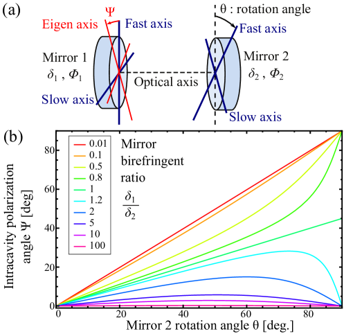
In the following, we consider two birefringent mirrors and with isotropic coatings and geometrical birefringences given respectively by and . By convention, the fast axis of is taken along the vertical direction and the fast axis of is rotated by an angle with respect to the one of (see Fig. 1(a)). When the mirrors are birefringent, the polarization eigenmodes inside the cavity can be calculated via the Jones matrix formalism [30]. As the ROCs in usual FFP cavities are much larger than the wavelengths, birefringent dephasing is small: . In the small phase approximation, the polarization eigenmodes in the cavity are linear and the ratio of the birefringent frequency splitting to the resonator linewidth (defined as Half Width Half Maximum in frequency) can be expressed as :
| (2) |
where is the finesse of the cavity and where we define the geometrical birefringence of the cavity, . The latter depends only on the shape of the two mirrors via and , and on their relative orientation . results only from the geometrical properties of the cavity while the resonant wavelength and the finesse featuring in depend only on the properties of the dielectric coating.
For applications where a given birefringence frequency splitting is needed, it can be adjusted by the angle between the two fast axes of the birefringent mirrors in the range . A perfect degenerate-mode cavity can only be obtained with mirrors that have exactly the same geometrical birefringence. However, variations in the shape productions lead to non-perfect cancellations of the cavity geometrical birefringence. A reliable solution to approach degeneracy is to use mirrors that have an excellent rotational symmetry and inherently a very low geometric birefringence. On the contrary, if a specific non-zero splitting is targeted, the best solution is to produce mirrors with approximately the same geometrical birefringence, slightly above one half of the targeted cavity one. The cavity birefringence will then be easily adjusted by a small rotation of one mirror remaining close to and thus being less sensitive to angle adjustment errors. If a precise absolute frequency splitting is needed, the wavelength and the length of the cavity must be taken into account to design the geometrical birefringence of the cavity according to the relation
| (3) |
where is the speed of light.
2.2 Polarization of the cavity mode for birefringent cavities
In an experiment with a non-degenerate cavity, the orientation of the polarization eigenmodes with respect to the complete apparatus can be of crucial importance. For example in atomic systems, it is required to achieve precise polarization dependent transitions for optical pumping.
If we consider the same setting as previously with two birefringent mirrors and with isotropic coatings and geometrical birefringence and , then the fast eigenmode of the cavity (i.e. the highest frequency mode) will have an angle relative to the fast axis of given by:
| (4) |
The value of the angle depends only on the ratio of the geometrical birefringence of the mirrors and on the angle between the fast axes of the two mirrors. The evolution of the angle of the polarization eigenmode basis is shown on Fig. 1(b). If the geometrical birefringence of one mirror is much larger than of the other one , then the eigenmode basis is aligned with the fast axis of the strongest birefringent mirror. When both are equal , the fast eigenmode is on the bisector of the fast axes of the two mirrors.
2.3 Spatial distribution of astigmatic cavity modes
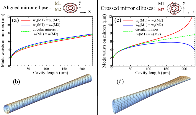
For applications where a maximal frequency splitting between the polarization eigenmodes is required, mirrors with strong geometrical birefringence are needed and the two fast axes have to be close to parallel. This implies to produce mirrors with very different radii along the two eigenaxes, noted and , which are then highly astigmatic. This affects the spatial distribution of the cavity mode. For the simple case of two identical mirrors with ROCs and and with parallel fast axes, the waists are located in the center of the cavity for both axes, but have a different value and for each one. The mode is then elliptical and the ratio of the waists for a cavity length is given by . If the length of the cavity is not too close to twice the smallest ROC, this ratio scales slowly with and stays roughly close to one. We are then close to the case of a circular cavity formed by two identical mirrors with a ROC corresponding to the average of and (see Fig. 2).
If instead a degenerate-mode cavity is targeted, a crossed configuration where the two fast axes of each mirror are orthogonal will minimize the cavity birefringence by compensating the geometrical one of each mirror. For two identical mirrors, the waists have the same value for both directions but their positions for each direction lie on opposite sides of the cavity center at a distance given by . When the resonator length tends toward the smallest ROC, the cavity gets closer to the limit of the stability region. The waists for each direction lie on the two opposite mirrors (on the mirror having the largest ROC along this direction) and the mode size on the facing mirror starts to diverge (see Fig. 2). This induces clipping losses that limit the finesse.
In the configuration where the fast axes of the two mirrors are neither parallel nor orthogonal, the cavity is twisted, featuring general astigmatism with a rotating elliptic intensity distribution along the resonator axis [31, 32, 33].
Beyond polarization control, our ability to produce mirrors with no rotational symmetry can be leveraged to tailor the spatial shape of cavity modes, for example to compensate the astigmatism of some ring cavity types.
3 Versatile CO2 laser dot machining of FFP cavity micromirrors
3.1 CO2 laser dot machining
We have recently developed a CO2 laser ablation setup, described in detail in [22], where the position of the fiber (or substrate) is controlled in all directions by a combination of state-of-the-art translation stages. This setup features several substantial improvements such as the automation of fiber alignment, in-situ phase-shifting profilometry and fast modification of the laser ablation beam diameter. Most importantly, it gives us the ability to carve structures into the fiber endfacets by using multiple laser pulses ("shots") precisely positioned relative to the fiber core center and with adjustable pulse lengths. This has allowed us to produce large circular fiber mirrors with large ROC, mandatory to realize FFP cavities longer than a millimeter [22].
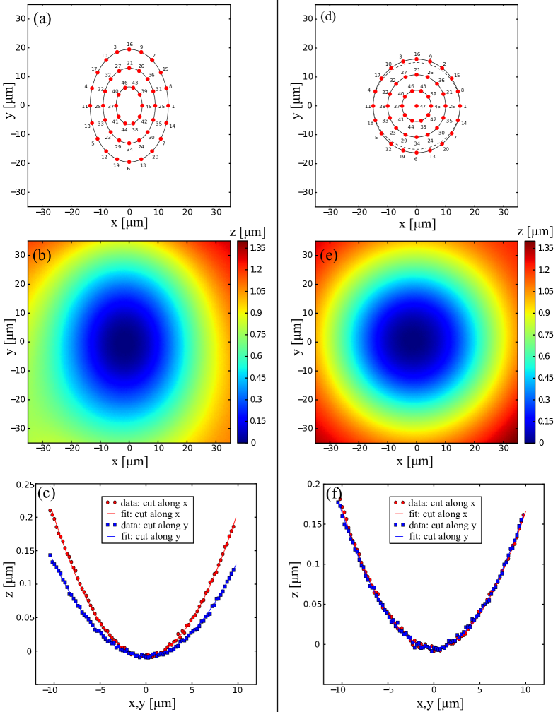
Moreover, this technique extends the range of realizable surface structures well beyond the circular symmetry while preserving the very low surface roughness required to sustain high finesse cavity modes and obtained thanks to surface tension smoothing [20]. The relative precision of the transverse motion of the substrate by the translation stages is below nm, thus offering unprecedented control over the shape of the carved structure via the choice of an adequate geometry of the shot pattern. In this article, we focus on the control of the elliptic shape of mirrors (and thus on the control of their birefringence) by using concentric elliptical shot patterns as shown on Fig. 3(a).
As the laser ablation is a highly non-linear process, finding a suitable shot pattern to produce elliptic paraboloidal structures needs at first some empirical investigations before a systematic optimization can be done. We mention here some general rules to converge towards such a pattern. First, neighboring shots should not be done consecutively to maintain a homogeneous heating of the substrate during the laser ablation process. As can be seen on Fig. 3(a), consecutive shots are separated by 3 positions in our optimized elliptical pattern. Second, for the same reason, we set a waiting time of second between two pulses. Third, the most centered shot should be done last, specially because the smoothing effect by surface tension occurs over a melted region of the mirror, which is much larger than the zone where single shot ablation occurs.
3.2 Elliptic paraboloidal micromirrors
Strongly elliptic paraboloidal structures were obtained by using shot patterns with a large ellipse radii ratio (typically close to 2), as the one presented on Fig. 3(a) that contains 46 shots. The shape shown on Fig. 3(b) is obtained by CO2 laser ablation of a multimode fiber (Cu50, IVG Fiber Ltd). We use a CO2 laser beam with a waist of 78m, a power of 750 mW, and single shot pulse length of 14.7 ms. We extract the two ROCs (m and m ) along the eigenaxes of the mirrors by using a bi-dimensional fit of the structure within a 10m radius around the center. By taking into account the measured nm standard deviation of the profilometry noise, the standard deviations of the fitted ROCs are much lower than m. The eigenaxes of the mirror are aligned with the eigenaxes, noted and , of the elliptical shot patterns. The cuts of the profile and of the bi-dimensional fit along these axes are presented on Fig. 3(c). The produced shape has mean absolute deviations from an elliptic paraboloid as small as nm over a circular region of interest which has a diameter of 30 m.
In order to tune the value of the mirrors geometric birefringences of different fiber types, we vary the single shot pulse length (between ms), the ratio of the shooting ellipse radii (over the range ) and the homothetic scaling of the shot positions. The mirror ROCs along the two eigenaxes were mostly designed to be in the range of respectively m and m and show correlated fluctuations from one fiber to another of about . By changing the pulse length and the scaling, we have tuned them from m and m up to m and m. This range was chosen according to the targeted characteristics of the cavity for our experiment which take into account the birefringent frequency splitting but also the mode waist and mode volume, the cavity stability and the mode coupling to the fibers modes. In particular, we aimed at stable cavities with length of about 100m and with relatively small mode volumes as required for CQED experiments. However, for other cavity geometries, the rotational asymmetry of the shape, and thus the geometric birefringence can be increased, if a large frequency splitting is needed.
3.3 Circular paraboloidal micromirrors
If nearly degenerate-mode cavities are targeted, mirrors with identical geometrical birefringence are required. To avoid extra alignment steps of mirror rotation and strongly asymmetric spatial distribution of the cavity mode, the best solution is to produce mirrors with very low geometric birefringence. However, the mirror shapes produced with a single shot technique usually show some residual asymmetry that stems from imperfections of the CO2 laser beam (non ideal circular polarized light, astigmatism). To eliminate this effect due to the lack of symmetry of the laser beam, one method is to rotate the fiber during the ablation process [27]. Here, we compensate for it with the CO2 dot machining method. We use a shot pattern with an ellipticity which is opposite to the ellipticity of the mirror’s cross-section obtained by a single shot as shown on Fig. 4(a). The processed fiber is Thorlabs 980HP, the CO2 beam waist is 78m, the produced ROCs are around 290m, and the shot pattern is the same as the one of Fig. 3(d)).
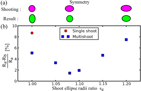
The relative difference of the ROCs of the two eigenaxes ROC when varying the pattern ellipticity are presented on Fig. 4(b). It is directly related to the geometrical birefringence by a factor which remains approximately constant for a given cavity design.
When we use the single shot technique, we obtain mirrors with %, where we have chosen the major axis to be vertical. The dot machining method with a circular pattern () improves due to the additional symmetry of the shooting pattern, but still presents a difference of about %. By using an elliptical shooting configuration whose major axis is orthogonal to the previous one (i.e. horizontal), we can reduce the asymmetry down to about % between the eigenaxes ROCs on average over several fibers. Some fibers in the set show a relative difference below %, as the one presented in Fig. 3(e,f), paving the way for a reliable realization of degenerated polarization modes in FFP cavities. Moreover, contrary to the technique that relies on fiber rotation, this method is easily applicable to any substrate.
4 Dual-wavelength operation of high-finesse FFP cavities
After producing the mirror structures, the fibers have been coated with a dual-wavelength high-reflective coating for 780 nm and 1559 nm (ion beam sputtering technique performed by Laseroptik GmbH). The choice of this coating is motivated by the specific application of our fiber cavities in the domain of CQED with neutral 87Rb atoms. In our experiment, the TEM00 cavity mode at 780 nm probes the 87Rb atoms on the D line, while the fundamental mode at 1559 nm acts as far-off-resonance optical lattice to trap the atoms along the cavity axis, achieving identical and maximal coupling to the probe.
4.1 Two types of FFP cavities
To inject the laser light in the fiber cavities, we use single-mode (SM) fibers in order to get a stable coupling, which is one of the key advantages of FFP cavities. The coupling efficiency results then from the overlap between the out-coming mode of the fiber (approximately Gaussian) and the cavity mode. To optimize the coupling and finesse, one fiber is mounted on a 3-axis translation stage with piezo actuators, while the second fiber is mounted on a 3-axis rotation stage. We have tested two different types of FFP cavities:
-
1.
SM-SM cavities: the 780 nm laser light is coupled into one fiber (IVG Cu800, SM from 770 nm to 1000 nm), while the 1559 nm light is coupled into the other one (IVG Cu1300, SM in the range 1250-1600 nm). These are commercial copper-coated fibers compatible with ultra-high vacuum applications. The light transmitted through the cavity at 780 nm can propagate efficiently in the SM fiber for 1559 nm, while the transmission at 1559 nm cannot be measured due to strong losses in the fiber for 780 nm.
-
2.
Photonic crystal (PC)-Multimode (MM) cavities: both 780 nm and 1559 nm lights are injected through an "endlessly single-mode" photonic crystal fiber with large mode area (LMA-10 from NKT Photonics). This fiber is specified for single-mode operation over a large wavelength interval. To be able to use this fiber in ultra-high vacuum, we replace the original acrylate coating with a home-made polyimide coating. The transmitted light is collected through the graded-index MM fiber (IVG Cu50) with essentially 100% efficiency for both wavelengths. The large mode diameter of the PC fibers that we choose allows us to achieve a better fiber-to-cavity coupling compared to the SM-SM configuration. PCF-MM cavities are also less sensitive to misalignment and centering imperfections than the SM-SM ones, due to the large acceptance of the MM fiber.
4.2 Finesse at 780 nm and 1559 nm
To measure the resonator finesse at both wavelengths, we first align a PC-MM cavity with two slightly elliptic paraboloidal fiber mirrors. We set the major axes to be orthogonal and measure the resonator finesse at both wavelengths. We perform this measurement by scanning the resonator length with a piezoelectric actuator and measuring the linewidth of the fundamental cavity mode at 780 nm and at 1559 nm in transmission. We use the sidebands generated by an electro-optic modulator for frequency calibration. A microscope is used to measure the cavity length with a precision of m, from which we calculate the free spectral-range. We perform the finesse measurement for different cavity lengths within the stability region, taking care of re-optimizing the alignment at every step. The results are shown on Fig. 5.
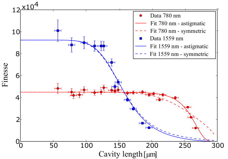
We observe that, when the cavity length is shorter than 100m, the finesse stays at its maximal value of (45 2)103 for 780 nm and (92 3)103 for 1559 nm, limited by the coating properties. As the length increases between 100m and 200m, the finesse at 1559 nm drops due to the effect of the clipping losses, which start playing a major role in reducing the finesse when the size of the mode on the mirrors grows. For cavity length above 200m, the finesse at 780 nm starts to decrease too. The mode at 780 nm is less affected by the clipping losses than the one at 1559 nm due to its smaller mode area by about a factor 2. Fabricating regular concave structures which are large enough to avoid clipping losses for the designed cavity length is then essential to achieve high finesse; our CO2 dot machining fabrication technique is a powerful tool in this sense, as shown in detail in [22].
To fit the data, we use the simple analytical model described in [2]. In this model, the cavity finesse is given by
| (5) |
where is the transmission through one mirror, are the absorption losses of the reflective coating, and are the scattering losses due to the surface roughness of the mirror (these values stand for one mirror and we suppose them identical for the two mirrors). are the clipping losses caused by the finite size of the mirror . The value of is determined from the finesse measurements on several short cavities, which give (702) ppm at 780 nm and (341) ppm at 1559 nm. The factor close to 2 between the losses for the two wavelengths stems from the term which we estimate to be roughly five times larger at 780 nm than at 1559 nm (measured value at 780 nm (352) ppm).
To take into account the elliptic paraboloidal structure of the mirror, we extend the previous model of the clipping losses[2, 22]. We associate to each mirror an effective elliptical cross-section with principal semi-axes and and we take into account the elliptical and astigmatic spatial distribution of the cavity mode. The mirror’s ellipse sets the size of the cut-off for the cavity mode through the relation
| (6) |
where are the mode radii along the principal axes of of the mirror .
Each dataset is fitted with this model, from which we deduce the effective size of the mirrors. The mode waists on the mirrors are deduced from the cavity length and from the ROCs of the fiber mirrors. They are slightly different for the two wavelengths. They are indeed extracted from the fibers profilometry data by using a bi-dimensional fit within a circular region, whose radius is the mode radius at the cavity length where clipping losses become dominant (i.e. the finesse drops to half of its maximum value). Since the fibers profile slightly deviates from an ideal elliptic paraboloid, the effective ROCs have a small dependence on the fitting region. For the measurement shown in Fig. 5, we set the fast axes of the mirrors to be orthogonal by finding the configuration that minimizes the birefringence.
We assume that the mirror shape is an asymmetric paraboloid, truncated at and respectively along and . This sets the constraint , where are the ROCs from the profilometry. Since our cavity is only slighlty asymmetric, it is difficult to estimate and independently with good confidence because, as remarked in [22], larger clipping loss on one mirror can be compensated by smaller losses on the other. We thus impose the additional constraint , i.e. that the cutoff occurs at the same depth on both mirrors.
The best fit curves give us a value of about 20m for the semi-axes of the elliptical cross-section describing the effective mirror size, with a difference of 1m between the major and minor axes. We also find a dependence of the effective size on the wavelength: the ones at 1559 nm exceed by about 2m the ones at 780 nm. At this distance of 20m from the center of the mirror, we notice on the profilometry data a deviation of about nm from the ideal parabolic profile, that rapidly increases further away.
We find good agreement between the data and the model within the experimental uncertainties, which indicates that no other main sources of loss are significantly affecting the cavity. For comparison, dashed lines in Fig. 5 show the results obtained by fitting our data by considering symmetric mirrors with a ROC equal to the average of the ROCs along the two principal axes. This corresponds to the situation where we neglect the asymmetry of the cavity mode, which becomes particularly important close to the instability region. We observe that such a model fits badly with our data at 780 nm (the level of statistical significance of the best-fit is less than 0.1%, in contrast to the 25% significance level that we obtain with the elliptical model) [34]. This wavelength is indeed more sensitive, as clipping losses starts to play a significant role closer to the instability region where the mode size on the mirror has a sharper variation with the cavity length. The effect of the astigmatism of the mode cannot be neglected especially in the situation where the two major-axes of the elliptical cross-section are orthogonal, which is the configuration which minimize the frequency splitting of the polarization eigenmodes.
5 Large birefringent frequency splitting with asymmetric mirrors
Knowing the finesse of the cavity at both wavelengths, we can now turn to the measurement of the birefringent frequency splitting of the polarization eigenmodes at 780 nm and at 1559 nm, and verify if both sets of data can be explained using the geometrical birefringence of the cavity. In order to achieve a large frequency splitting, we use mirror shapes, as the one presented in Fig. 3(b), which have radii of curvature of about 350m and 250m along their eigenaxes.
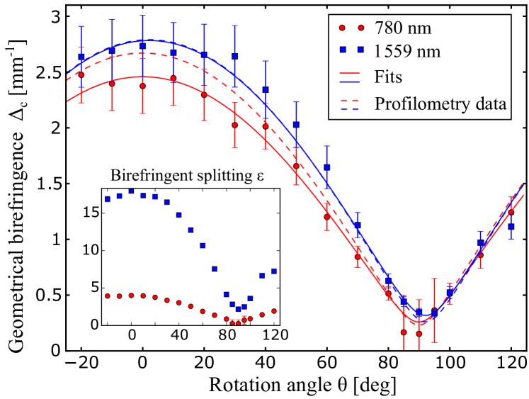
To measure the birefringent frequency splitting, we align a FFP cavity with two SM fibers. The resonator length is set to m and we rotate one of the fiber around its axis. The relatively short length facilitates the required re-optimisation of the cavity alignment after a rotation step. We observe the evolution of the absolute birefringent frequency splitting and the cavity linewidth for the two wavelengths. The birefringent frequency splitting data is shown on the inset of the Figure 6. The difference by approximately a factor 4 in the splitting between the two data sets stems from the wavelength dependence of Eq. 2 and from the higher finesse at 1559 nm () than at 780 nm ().
Figure 6 shows the geometrical birefringence obtained by dividing the birefringent frequency splitting by the wavelength, the finesse and (see Eq. 2). The fact that the two sets of data are relatively close to each other confirms that the birefringent frequency splitting originates from the geometrical asymmetry of the mirrors.
The small remaining mismatch can be explained by the slight differences in the effective ROCs seen by the two wavelengths. Indeed, the effective area of the mirror seen by the cavity mode is twice larger at 1559 nm than at 780 nm. From the profilometry measurement, we calculate the geometrical birefringence of each mirror for the two wavelengths: at 780 nm and at 1559 nm, where the number in parentheses is the numerical value of standard uncertainty referred to the corresponding last digits of the quoted result. We can then deduce the expected cavity geometrical birefringences for the two wavelengths, which are plotted in dotted lines. When fitting with the geometrical birefringence of each mirror as parameters, we obtain a good matching of fitted curves (full lines) with the data points for the following values at 780 nm and at 1559 nm. The fitted geometric birefringences at 780 nm are slightly lower than the predicted values, which correspond to the small shift of the data points to lower values. We attribute the remaining mismatch to slight differences between the effective ROCs actually experienced by the cavity mode and the ones given by the fit of profilometry data in the center of the cavity. Indeed, the actual position of the cavity mode can deviate slightly from the center of the fiber while maintaining a good finesse and coupling, which were the parameters we optimized during the alignment. Thus, slight deviations of the profile from an ideal paraboloid and small variations of the mode position on the mirror lead to small differences in the effective ROCs. Nevertheless, all data points lie within a % uncertainty range on the ROCs given by the profilometry measurement. This confirms that the geometric birefringence of the mirrors extracted from in-situ profilometry can be used to predict the actual geometrical birefringence of the cavity, which is the key parameter that controls the birefringent splitting for a given finesse and wavelength. Our laser ablation setup with multiple pulses and profilometry allows us to realize and characterize fiber mirror shapes with sufficient precision to reach such a control and be able to tailor the birefringence properties of fiber cavities.
6 Conclusion
We have demonstrated how the laser dot machining method allows controlling the birefringence of fiber Fabry-Perot cavities. By defining the geometrical birefringence, we quantify the intrinsic geometric property of a mirror that leads to frequency splitting of the polarization eigenmodes. We discussed the polarization and spatial modes of the cavity in the case of asymmetric mirrors. Our laser ablation technique with multiple pulses in a precise pattern has been used to produce elliptic paraboloidal shapes on the fiber endfacets. Elliptical pulse patterns lead to strongly asymmetrical shapes with large geometric birefringences. The same method can also be used to obtain cavities with very low geometric birefringence by producing mirror shapes with very small asymmetry without rotation of the substrate thanks to optimized pulses patterns. We have realized fiber cavities that are resonant in two frequency bands separated by an octave with a specific dual-wavelength coating deposited on the machined fibers. High-finesse operation can be achieved with SM-SM and PCF-MM fiber cavities that ensure stable injection at both wavelengths. In the context of elliptic paraboloidal mirrors, the astigmatic spatial distribution of the mode needs to be taken into account to describe the clipping losses limit of long cavities. We observed geometric birefringences of a cavity at both wavelengths with identical values within the measurement precision, and consistent with the profilometry data. This result directly confirms the geometric origin of the birefringent frequency splitting of fiber Fabry-Perot cavities.
The precise control of the polarization opens new opportunities for fiber cavity applications, especially for cavity QED experiments, allowing either large frequency polarization eigenmodes splitting or degenerate mode configuration. In addition to the polarization, non-symmetric structures carved into a substrate can also be used to tailor the spatial distribution of the cavity mode. The extension of the laser dot machining technique to produce shapes beyond the simple rotational symmetry also constitutes a first step towards realization of more complex microscopic structures to engineer new types of stable optical resonators.
Funding
This work was supported by the Agence Nationale de la Recherche (ANR) (SAROCEMA project, ANR-14-CE32-0002) and the European Research Council (ERC) (Advanced Grant “EQUEMI”, GA 671133).
Acknowledgments
We thank K. Schüppert for contributions in the early stage of the experiment. While finalizing the manuscript, we become aware of a related method of producing asymmetric mirrors [35].